Page 1985 of 3051
YEL451C
POWER WINDOW
Wiring Diagram Ð WINDOW Ð (Cont'd)
EL-254
Page 1986 of 3051
YEL452C
POWER WINDOW
Wiring Diagram Ð WINDOW Ð (Cont'd)
EL-255
Page 1987 of 3051

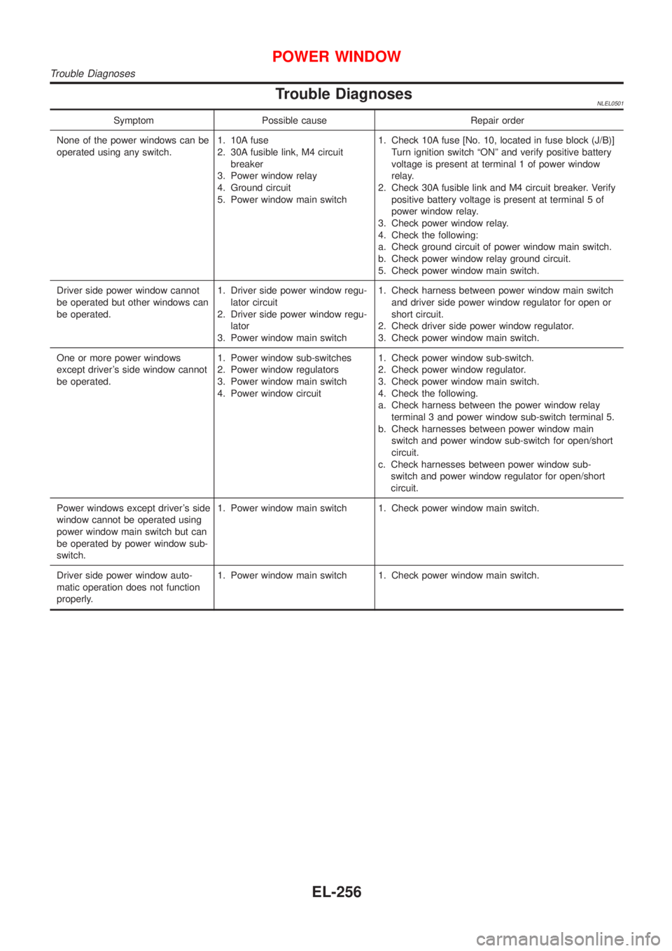
Trouble DiagnosesNLEL0501
Symptom Possible cause Repair order
None of the power windows can be
operated using any switch.1. 10A fuse
2. 30A fusible link, M4 circuit
breaker
3. Power window relay
4. Ground circuit
5. Power window main switch1. Check 10A fuse [No. 10, located in fuse block (J/B)]
Turn ignition switch ªONº and verify positive battery
voltage is present at terminal 1 of power window
relay.
2. Check 30A fusible link and M4 circuit breaker. Verify
positive battery voltage is present at terminal 5 of
power window relay.
3. Check power window relay.
4. Check the following:
a. Check ground circuit of power window main switch.
b. Check power window relay ground circuit.
5. Check power window main switch.
Driver side power window cannot
be operated but other windows can
be operated.1. Driver side power window regu-
lator circuit
2. Driver side power window regu-
lator
3. Power window main switch1. Check harness between power window main switch
and driver side power window regulator for open or
short circuit.
2. Check driver side power window regulator.
3. Check power window main switch.
One or more power windows
except driver's side window cannot
be operated.1. Power window sub-switches
2. Power window regulators
3. Power window main switch
4. Power window circuit1. Check power window sub-switch.
2. Check power window regulator.
3. Check power window main switch.
4. Check the following.
a. Check harness between the power window relay
terminal 3 and power window sub-switch terminal 5.
b. Check harnesses between power window main
switch and power window sub-switch for open/short
circuit.
c. Check harnesses between power window sub-
switch and power window regulator for open/short
circuit.
Power windows except driver's side
window cannot be operated using
power window main switch but can
be operated by power window sub-
switch.1. Power window main switch 1. Check power window main switch.
Driver side power window auto-
matic operation does not function
properly.1. Power window main switch 1. Check power window main switch.
POWER WINDOW
Trouble Diagnoses
EL-256
Page 2005 of 3051
DOOR LOCK/UNLOCK SWITCH CHECK=NLEL0505S04
1 CHECK DOOR LOCK/UNLOCK SWITCH INPUT SIGNAL
1. Disconnect time control unit harness connector.
2. Check continuity between time control unit harness connector terminal 37 or 38 and ground.
NEL674
Refer to wiring diagram.
OK or NG
OK©Door lock/unlock switch is OK.
NG©GO TO 2.
2 CHECK DOOR LOCK/UNLOCK SWITCH
1. Disconnect door lock/unlock switch harness connector.
2. Check continuity between each door lock/unlock switch terminals.
+Power window main switch (Door lock/unlock switch)
NEL675
OK or NG
OK©Check the following.
+Ground circuit for door lock/unlock switch
+Harness for open or short between door lock/unlock switch and time control unit con-
nector
NG©Replace door lock/unlock switch.
POWER DOOR LOCK
Trouble Diagnoses/LHD Models (Cont'd)
EL-274
Page 2034 of 3051
DOOR LOCK/UNLOCK SWITCH CHECK=NLEL0477S04
1 CHECK DOOR LOCK/UNLOCK SWITCH INPUT SIGNAL
1. Disconnect time control unit harness connector.
2. Check continuity between time control unit harness connector terminal 37 or 38 and ground.
NEL674
Refer to wiring diagram.
OK or NG
OK©Door lock/unlock switch is OK.
NG©GO TO 2.
2 CHECK DOOR LOCK/UNLOCK SWITCH
1. Disconnect door lock/unlock switch harness connector.
2. Check continuity between each door lock/unlock switch terminals.
+Power window main switch (Door lock/unlock switch)
NEL684
OK or NG
OK©Check the following.
+Ground circuit for door lock/unlock switch
+Harness for open or short between door lock/unlock switch and time control unit con-
nector
NG©Replace door lock/unlock switch.
POWER DOOR LOCK Ð SUPER LOCK Ð
Trouble Diagnoses/RHD Models (Cont'd)
EL-303
Page 2057 of 3051

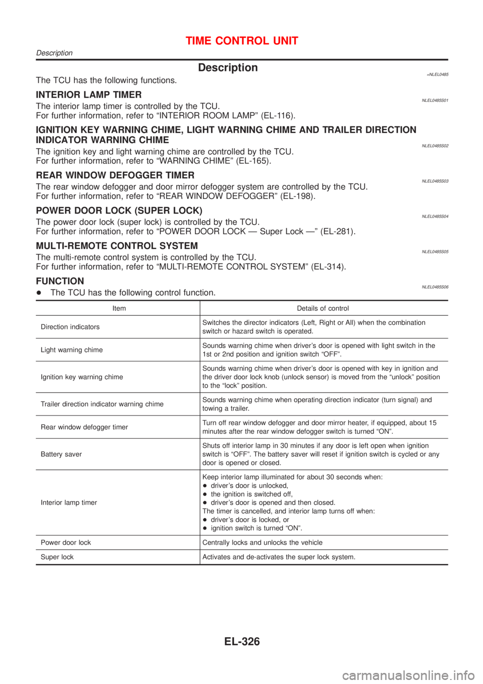
Description=NLEL0485The TCU has the following functions.
INTERIOR LAMP TIMERNLEL0485S01The interior lamp timer is controlled by the TCU.
For further information, refer to ªINTERIOR ROOM LAMPº (EL-116).
IGNITION KEY WARNING CHIME, LIGHT WARNING CHIME AND TRAILER DIRECTION
INDICATOR WARNING CHIME
NLEL0485S02The ignition key and light warning chime are controlled by the TCU.
For further information, refer to ªWARNING CHIMEº (EL-165).
REAR WINDOW DEFOGGER TIMERNLEL0485S03The rear window defogger and door mirror defogger system are controlled by the TCU.
For further information, refer to ªREAR WINDOW DEFOGGERº (EL-198).
POWER DOOR LOCK (SUPER LOCK)NLEL0485S04The power door lock (super lock) is controlled by the TCU.
For further information, refer to ªPOWER DOOR LOCK Ð Super Lock к (EL-281).
MULTI-REMOTE CONTROL SYSTEMNLEL0485S05The multi-remote control system is controlled by the TCU.
For further information, refer to ªMULTI-REMOTE CONTROL SYSTEMº (EL-314).
FUNCTIONNLEL0485S06+The TCU has the following control function.
Item Details of control
Direction indicatorsSwitches the director indicators (Left, Right or All) when the combination
switch or hazard switch is operated.
Light warning chimeSounds warning chime when driver's door is opened with light switch in the
1st or 2nd position and ignition switch ªOFFº.
Ignition key warning chimeSounds warning chime when driver's door is opened with key in ignition and
the driver door lock knob (unlock sensor) is moved from the ªunlockº position
to the ªlockº position.
Trailer direction indicator warning chimeSounds warning chime when operating direction indicator (turn signal) and
towing a trailer.
Rear window defogger timerTurn off rear window defogger and door mirror heater, if equipped, about 15
minutes after the rear window defogger switch is turned ªONº.
Battery saverShuts off interior lamp in 30 minutes if any door is left open when ignition
switch is ªOFFº. The battery saver will reset if ignition switch is cycled or any
door is opened or closed.
Interior lamp timerKeep interior lamp illuminated for about 30 seconds when:
+driver's door is unlocked,
+the ignition is switched off,
+driver's door is opened and then closed.
The timer is cancelled, and interior lamp turns off when:
+driver's door is locked, or
+ignition switch is turned ªONº.
Power door lock Centrally locks and unlocks the vehicle
Super lock Activates and de-activates the super lock system.
TIME CONTROL UNIT
Description
EL-326
Page 2256 of 3051

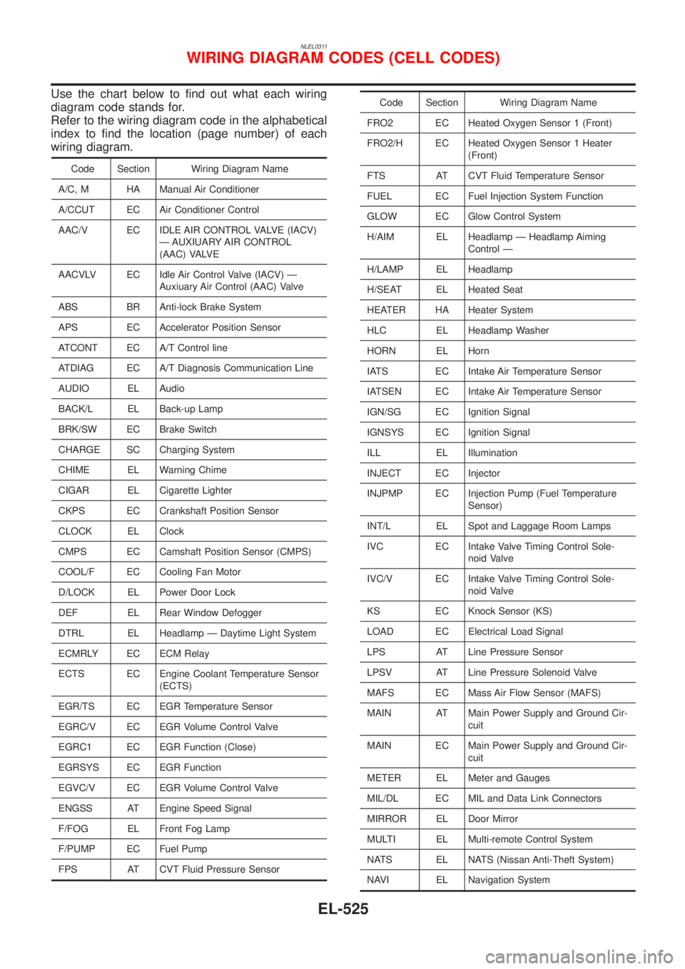
NLEL0311
Use the chart below to find out what each wiring
diagram code stands for.
Refer to the wiring diagram code in the alphabetical
index to find the location (page number) of each
wiring diagram.
Code Section Wiring Diagram Name
A/C, M HA Manual Air Conditioner
A/CCUT EC Air Conditioner Control
AAC/V EC IDLE AIR CONTROL VALVE (IACV)
Ð AUXIUARY AIR CONTROL
(AAC) VALVE
AACVLV EC Idle Air Control Valve (IACV) Ð
Auxiuary Air Control (AAC) Valve
ABS BR Anti-lock Brake System
APS EC Accelerator Position Sensor
ATCONT EC A/T Control line
ATDIAG EC A/T Diagnosis Communication Line
AUDIO EL Audio
BACK/L EL Back-up Lamp
BRK/SW EC Brake Switch
CHARGE SC Charging System
CHIME EL Warning Chime
CIGAR EL Cigarette Lighter
CKPS EC Crankshaft Position Sensor
CLOCK EL Clock
CMPS EC Camshaft Position Sensor (CMPS)
COOL/F EC Cooling Fan Motor
D/LOCK EL Power Door Lock
DEF EL Rear Window Defogger
DTRL EL Headlamp Ð Daytime Light System
ECMRLY EC ECM Relay
ECTS EC Engine Coolant Temperature Sensor
(ECTS)
EGR/TS EC EGR Temperature Sensor
EGRC/V EC EGR Volume Control Valve
EGRC1 EC EGR Function (Close)
EGRSYS EC EGR Function
EGVC/V EC EGR Volume Control Valve
ENGSS AT Engine Speed Signal
F/FOG EL Front Fog Lamp
F/PUMP EC Fuel Pump
FPS AT CVT Fluid Pressure Sensor
Code Section Wiring Diagram Name
FRO2 EC Heated Oxygen Sensor 1 (Front)
FRO2/H EC Heated Oxygen Sensor 1 Heater
(Front)
FTS AT CVT Fluid Temperature Sensor
FUEL EC Fuel Injection System Function
GLOW EC Glow Control System
H/AIM EL Headlamp Ð Headlamp Aiming
Control Ð
H/LAMP EL Headlamp
H/SEAT EL Heated Seat
HEATER HA Heater System
HLC EL Headlamp Washer
HORN EL Horn
IATS EC Intake Air Temperature Sensor
IATSEN EC Intake Air Temperature Sensor
IGN/SG EC Ignition Signal
IGNSYS EC Ignition Signal
ILL EL Illumination
INJECT EC Injector
INJPMP EC Injection Pump (Fuel Temperature
Sensor)
INT/L EL Spot and Laggage Room Lamps
IVC EC Intake Valve Timing Control Sole-
noid Valve
IVC/V EC Intake Valve Timing Control Sole-
noid Valve
KS EC Knock Sensor (KS)
LOAD EC Electrical Load Signal
LPS AT Line Pressure Sensor
LPSV AT Line Pressure Solenoid Valve
MAFS EC Mass Air Flow Sensor (MAFS)
MAIN AT Main Power Supply and Ground Cir-
cuit
MAIN EC Main Power Supply and Ground Cir-
cuit
METER EL Meter and Gauges
MIL/DL EC MIL and Data Link Connectors
MIRROR EL Door Mirror
MULTI EL Multi-remote Control System
NATS EL NATS (Nissan Anti-Theft System)
NAVI EL Navigation System
WIRING DIAGRAM CODES (CELL CODES)
EL-525
Page 2257 of 3051

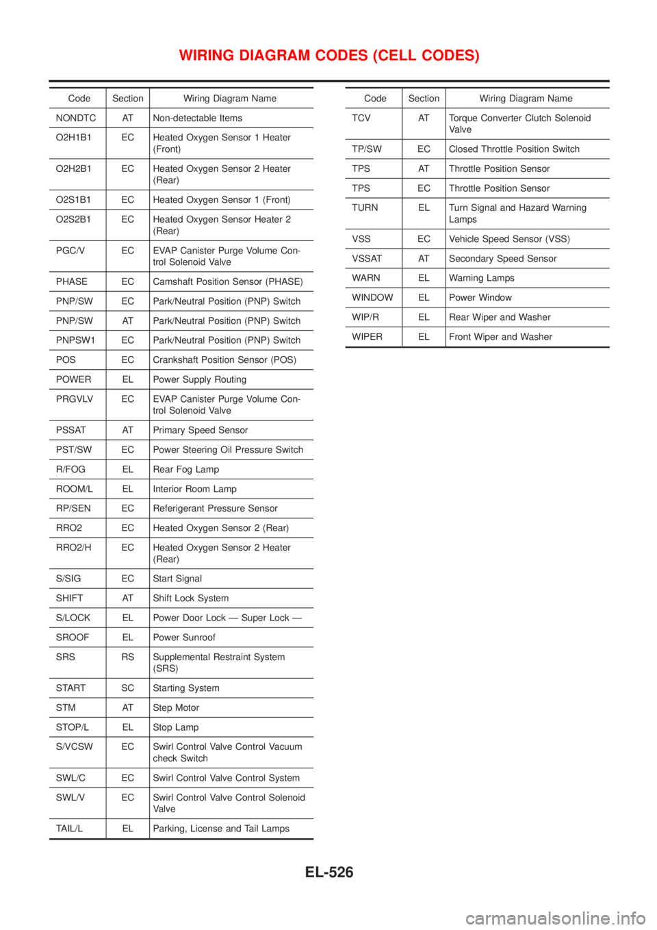
Code Section Wiring Diagram Name
NONDTC AT Non-detectable Items
O2H1B1 EC Heated Oxygen Sensor 1 Heater
(Front)
O2H2B1 EC Heated Oxygen Sensor 2 Heater
(Rear)
O2S1B1 EC Heated Oxygen Sensor 1 (Front)
O2S2B1 EC Heated Oxygen Sensor Heater 2
(Rear)
PGC/V EC EVAP Canister Purge Volume Con-
trol Solenoid Valve
PHASE EC Camshaft Position Sensor (PHASE)
PNP/SW EC Park/Neutral Position (PNP) Switch
PNP/SW AT Park/Neutral Position (PNP) Switch
PNPSW1 EC Park/Neutral Position (PNP) Switch
POS EC Crankshaft Position Sensor (POS)
POWER EL Power Supply Routing
PRGVLV EC EVAP Canister Purge Volume Con-
trol Solenoid Valve
PSSAT AT Primary Speed Sensor
PST/SW EC Power Steering Oil Pressure Switch
R/FOG EL Rear Fog Lamp
ROOM/L EL Interior Room Lamp
RP/SEN EC Referigerant Pressure Sensor
RRO2 EC Heated Oxygen Sensor 2 (Rear)
RRO2/H EC Heated Oxygen Sensor 2 Heater
(Rear)
S/SIG EC Start Signal
SHIFT AT Shift Lock System
S/LOCK EL Power Door Lock Ð Super Lock Ð
SROOF EL Power Sunroof
SRS RS Supplemental Restraint System
(SRS)
START SC Starting System
STM AT Step Motor
STOP/L EL Stop Lamp
S/VCSW EC Swirl Control Valve Control Vacuum
check Switch
SWL/C EC Swirl Control Valve Control System
SWL/V EC Swirl Control Valve Control Solenoid
Valve
TAIL/L EL Parking, License and Tail LampsCode Section Wiring Diagram Name
TCV AT Torque Converter Clutch Solenoid
Valve
TP/SW EC Closed Throttle Position Switch
TPS AT Throttle Position Sensor
TPS EC Throttle Position Sensor
TURN EL Turn Signal and Hazard Warning
Lamps
VSS EC Vehicle Speed Sensor (VSS)
VSSAT AT Secondary Speed Sensor
WARN EL Warning Lamps
WINDOW EL Power Window
WIP/R EL Rear Wiper and Washer
WIPER EL Front Wiper and Washer
WIRING DIAGRAM CODES (CELL CODES)
EL-526