2001 NISSAN ALMERA TINO seats
[x] Cancel search: seatsPage 2259 of 3051
REPLACEMENT OF CONNECTING ROD
BUSHING (SMALL END)
..........................................60
FLYWHEEL RUNOUT..............................................60
Assembly ...................................................................60
PISTON..................................................................60
CRANKSHAFT.........................................................61
SERVICE DATA AND SPECIFICATIONS (SDS).........64
General Specifications ...............................................64
Compression Pressure ..............................................64
Belt Deflection............................................................64
Spark Plug .................................................................65
Cylinder Head ............................................................65
Valve ..........................................................................65
VALVE....................................................................65
VALVE SPRING.......................................................65
VALVE LIFTER........................................................66
VALVE CLEARANCE................................................67
VALVE GUIDE.........................................................67
AVAILABLE SHIMS..................................................67
VALVE SEAT...........................................................70
VALVE SEAT RESURFACE LIMIT.............................71
Camshaft and Camshaft Bearing ..............................71
Cylinder Block ............................................................72
Piston, Piston Ring and Piston Pin ...........................73
PISTON..................................................................73
PISTON RING.........................................................73
PISTON PIN............................................................73
Connecting Rod .........................................................74
Crankshaft..................................................................74
Main Bearing..............................................................74
STANDARD.............................................................74
UNDERSIZE............................................................74
Connecting Rod Bearing ...........................................75
STANDARD SIZE....................................................75
UNDERSIZE............................................................75
Bearing Clearance .....................................................75
Miscellaneous Components.......................................75
SR
PRECAUTIONS.............................................................76
Parts Requiring Angular Tightening ...........................76
Liquid Gasket Application Procedure ........................76
PREPARATION.............................................................77
Special Service Tools ................................................77
Commercial Service Tools .........................................79
NOISE, VIBRATION AND HARSHNESS (NVH)
TROUBLESHOOTING...................................................80
NVH Troubleshooting - Engine Noise .......................81
OUTER COMPONENT PARTS.....................................82
Removal and Installation ...........................................82
MEASUREMENT OF COMPRESSION PRESSURE....85
DRIVE BELTS................................................................86
Checking ....................................................................86AIR CLEANER...............................................................88
Changing Air Cleaner Filter .......................................88
VISCOUS PAPER TYPE...........................................88
SPARK PLUG................................................................89
Checking and Changing Spark Plugs .......................89
Checking Ignition Leads ............................................90
OIL PAN.........................................................................91
Components...............................................................91
Removal .....................................................................91
Installation ..................................................................93
TIMING CHAIN..............................................................96
Components...............................................................96
Removal .....................................................................97
Inspection.................................................................100
Installation ................................................................100
OIL SEAL.....................................................................105
Replacement ............................................................105
VALVE OIL SEAL...................................................105
FRONT OIL SEAL..................................................105
REAR OIL SEAL....................................................107
CYLINDER HEAD........................................................108
Components.............................................................108
Removal ...................................................................109
Disassembly............................................................. 111
Inspection................................................................. 113
CYLINDER HEAD DISTORTION............................. 113
CAMSHAFT VISUAL CHECK.................................. 114
CAMSHAFT RUNOUT............................................ 114
CAMSHAFT CAM HEIGHT..................................... 114
CAMSHAFT JOURNAL CLEARANCE...................... 115
CAMSHAFT END PLAY.......................................... 115
CAMSHAFT SPROCKET RUNOUT......................... 116
VALVE GUIDE CLEARANCE.................................. 116
VALVE GUIDE REPLACEMENT.............................. 116
VALVE SEATS....................................................... 117
REPLACING VALVE SEAT FOR SERVICE PARTS.. 118
VALVE DIMENSIONS............................................. 119
VALVE SPRING..................................................... 119
HYDRAULIC LASH ADJUSTER.............................. 119
ROCKER ARM, SHIM AND ROCKER ARM GUIDE...120
Assembly .................................................................120
Installation ................................................................123
ENGINE ASSEMBLY...................................................130
Removal and Installation .........................................130
REMOVAL.............................................................131
INSTALLATION......................................................132
CYLINDER BLOCK.....................................................133
Components.............................................................133
Removal and Installation .........................................134
Disassembly.............................................................134
PISTON AND CRANKSHAFT..................................134
Inspection.................................................................134
PISTON AND PISTON PIN CLEARANCE................134
PISTON RING SIDE CLEARANCE..........................135
CONTENTS(Cont'd)
EM-2
Page 2261 of 3051
Components.............................................................200
Removal ...................................................................201
PREPARATIVE WORK...........................................201
CAMSHAFT...........................................................201
CYLINDER HEAD..................................................202
Disassembly.............................................................202
Inspection.................................................................203
CYLINDER HEAD DISTORTION.............................203
CAMSHAFT VISUAL CHECK..................................204
CAMSHAFT RUNOUT............................................204
CAMSHAFT CAM HEIGHT.....................................204
CAMSHAFT JOURNAL CLEARANCE......................204
CAMSHAFT END PLAY..........................................205
CAMSHAFT SPROCKET RUNOUT.........................205
VALVE GUIDE CLEARANCE..................................205
VALVE GUIDE REPLACEMENT..............................206
VALVE SEATS.......................................................207
REPLACING VALVE SEAT FOR SERVICE PARTS..207
VALVE DIMENSIONS.............................................209
VALVE SPRING.....................................................209
VALVE LIFTER......................................................209
Assembly .................................................................210
Installation ................................................................210
CYLINDER HEAD GASKET SELECTION.................210
CYLINDER HEAD BOLT DEFORMATION CHECK... 211
CYLINDER HEAD-TO-BLOCK DIFFERENCE
CHECK
.................................................................212
LIQUID GASKET APPLICATION ON REAR CHAIN
CASE
....................................................................212
CYLINDER HEAD INSTALLATION..........................212
GLOW PLUG INSTALLATION.................................212
CAMSHAFT INSTALLATION...................................213
Valve Clearance.......................................................214
CHECKING...........................................................214
ADJUSTING..........................................................215
ENGINE ASSEMBLY...................................................218
Removal and Installation .........................................218
REMOVAL.............................................................219
INSTALLATION......................................................220
CYLINDER BLOCK.....................................................221
Components.............................................................221
Removal and Installation .........................................222
Disassembly.............................................................222
PISTON AND CRANKSHAFT..................................222
Inspection.................................................................225
CRANKSHAFT END PLAY.....................................225
CONNECTING ROD SIDE CLEARANCE.................225
PISTON AND PISTON PIN CLEARANCE................226
PISTON RING SIDE CLEARANCE..........................226
PISTON RING END GAP........................................226
CONNECTING ROD BEND AND TORSION.............227
CYLINDER BLOCK DISTORTION AND WEAR.........227
PISTON-TO-BORE CLEARANCE............................228
CRANKSHAFT.......................................................229
MAIN BEARING HOUSING INNER DIAMETER........230
BEARING CLEARANCE.........................................230
MAIN BEARING CRUSH HEIGHT...........................234
MAIN BEARING CAP BOLT DEFORMATION...........234
CONNECTING ROD BUSHING CLEARANCE
(SMALL END)
........................................................234
CONNECTING ROD BOLT DEFORMATION............235
FLYWHEEL RUNOUT............................................235
OIL JET................................................................235
OIL JET RELIEF VALVE.........................................235
Assembly .................................................................236
PISTON................................................................236
CRANKSHAFT.......................................................236
REPLACEMENT OF PILOT BUSHING.....................239
SERVICE DATA AND SPECIFICATIONS (SDS).......241
General Specifications .............................................241
Compression Pressure ............................................241
Belt Deflection..........................................................241
Cylinder Head ..........................................................241
Valve ........................................................................242
VALVE..................................................................242
VALVE CLEARANCE..............................................242
AVAILABLE SHIMS................................................242
VALVE SPRING.....................................................243
VALVE LIFTER......................................................243
VALVE GUIDE.......................................................244
Valve Seat................................................................245
Camshaft and Camshaft Bearing ............................247
Cylinder Block ..........................................................248
Piston, Piston Ring and Piston Pin .........................248
AVAILABLE PISTON..............................................248
PISTON RING.......................................................249
PISTON PIN..........................................................249
Connecting Rod .......................................................249
Crankshaft................................................................249
Available Main Bearing ............................................250
UNDERSIZE..........................................................250
Available Connecting Rod Bearing..........................250
CONNECTING ROD BEARING...............................250
UNDERSIZE..........................................................251
Miscellaneous Components.....................................251
BEARING CLEARANCE.........................................251
CONTENTS(Cont'd)
EM-4
Page 2297 of 3051
SEM932C
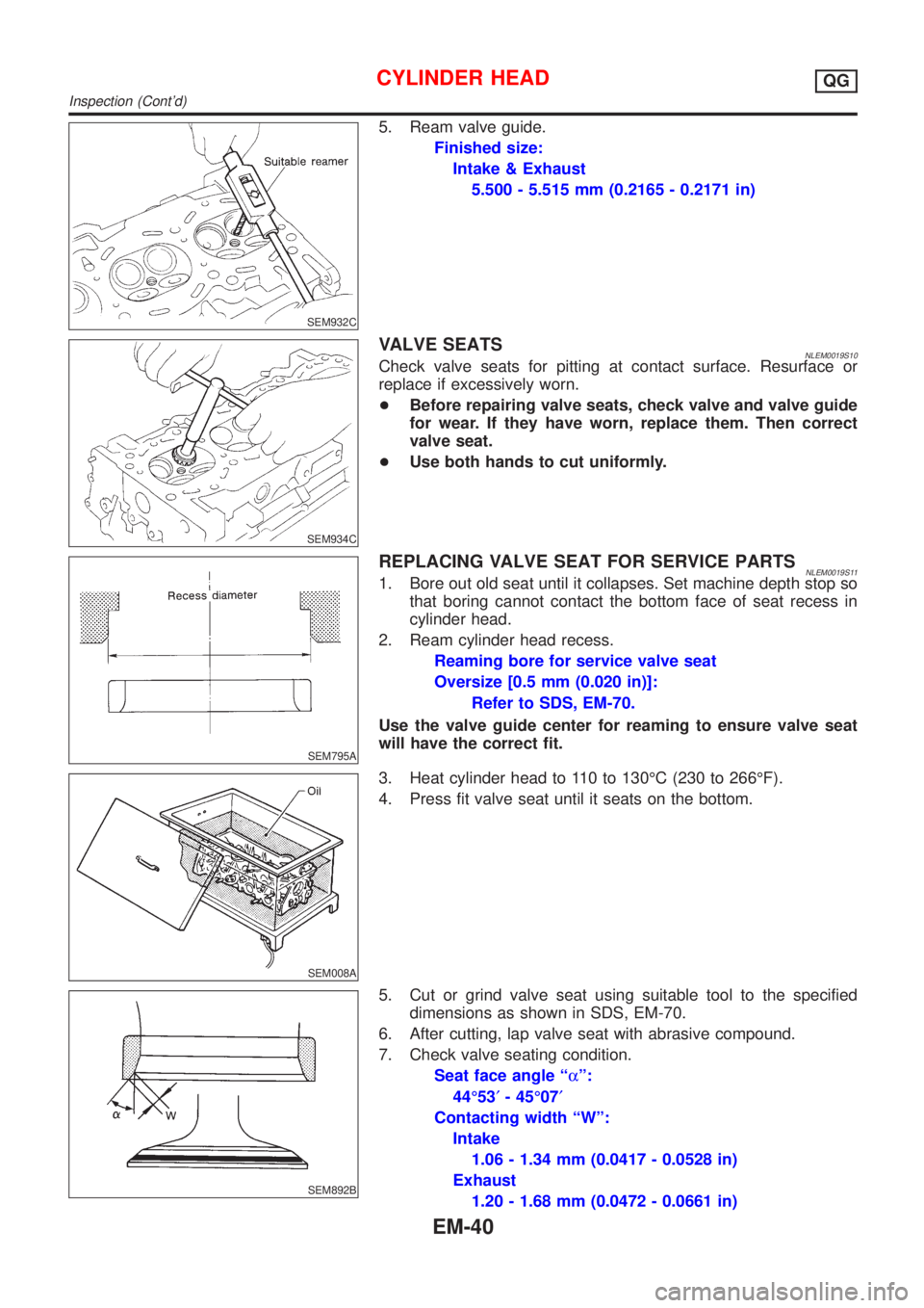
5. Ream valve guide.
Finished size:
Intake & Exhaust
5.500 - 5.515 mm (0.2165 - 0.2171 in)
SEM934C
VALVE SEATSNLEM0019S10Check valve seats for pitting at contact surface. Resurface or
replace if excessively worn.
+Before repairing valve seats, check valve and valve guide
for wear. If they have worn, replace them. Then correct
valve seat.
+Use both hands to cut uniformly.
SEM795A
REPLACING VALVE SEAT FOR SERVICE PARTSNLEM0019S111. Bore out old seat until it collapses. Set machine depth stop so
that boring cannot contact the bottom face of seat recess in
cylinder head.
2. Ream cylinder head recess.
Reaming bore for service valve seat
Oversize [0.5 mm (0.020 in)]:
Refer to SDS, EM-70.
Use the valve guide center for reaming to ensure valve seat
will have the correct fit.
SEM008A
3. Heat cylinder head to 110 to 130ÉC (230 to 266ÉF).
4. Press fit valve seat until it seats on the bottom.
SEM892B
5. Cut or grind valve seat using suitable tool to the specified
dimensions as shown in SDS, EM-70.
6. After cutting, lap valve seat with abrasive compound.
7. Check valve seating condition.
Seat face angle ªaº:
44É53¢- 45É07¢
Contacting width ªWº:
Intake
1.06 - 1.34 mm (0.0417 - 0.0528 in)
Exhaust
1.20 - 1.68 mm (0.0472 - 0.0661 in)
CYLINDER HEADQG
Inspection (Cont'd)
EM-40
Page 2374 of 3051
![NISSAN ALMERA TINO 2001 Service Repair Manual SEM931C
2. Drive out valve guide with a press [under a 20 kN (2 ton, 2.2
US ton, 2.0 Imp ton) pressure] or hammer and suitable tool.
SEM932C
3. Ream cylinder head valve guide hole.
Valve guide hole di NISSAN ALMERA TINO 2001 Service Repair Manual SEM931C
2. Drive out valve guide with a press [under a 20 kN (2 ton, 2.2
US ton, 2.0 Imp ton) pressure] or hammer and suitable tool.
SEM932C
3. Ream cylinder head valve guide hole.
Valve guide hole di](/manual-img/5/57352/w960_57352-2373.png)
SEM931C
2. Drive out valve guide with a press [under a 20 kN (2 ton, 2.2
US ton, 2.0 Imp ton) pressure] or hammer and suitable tool.
SEM932C
3. Ream cylinder head valve guide hole.
Valve guide hole diameter
(for service parts):
Intake & Exhaust
10.175 - 10.196 mm (0.4006 - 0.4014 in)
SEM083D
4. Heat cylinder head to 110 to 130ÉC (230 to 266ÉF) and press
service valve guide into cylinder head.
Projection ªLº:
14.0 - 14.2 mm (0.551 - 0.559 in)
SEM932C
5. Ream valve guide.
Finished size:
Intake & Exhaust
6.000 - 6.018 mm (0.2362 - 0.2369 in)
SEM934C
VALVE SEATSNLEM0133S10Check valve seats for pitting at contact surface. Resurface or
replace if excessively worn.
+Before repairing valve seats, check valve and valve guide
for wear. If they are worn, replace them. Then correct valve
seat.
+Use both hands to cut uniformly.
CYLINDER HEADSR
Inspection (Cont'd)
EM-117
Page 2375 of 3051
SEM795A
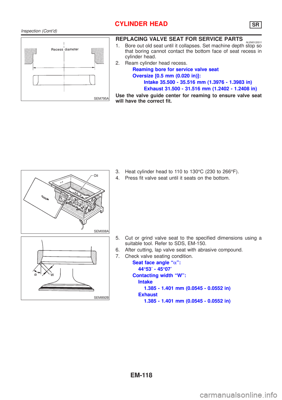
REPLACING VALVE SEAT FOR SERVICE PARTSNLEM0133S111. Bore out old seat until it collapses. Set machine depth stop so
that boring cannot contact the bottom face of seat recess in
cylinder head.
2. Ream cylinder head recess.
Reaming bore for service valve seat
Oversize [0.5 mm (0.020 in)]:
Intake 35.500 - 35.516 mm (1.3976 - 1.3983 in)
Exhaust 31.500 - 31.516 mm (1.2402 - 1.2408 in)
Use the valve guide center for reaming to ensure valve seat
will have the correct fit.
SEM008A
3. Heat cylinder head to 110 to 130ÉC (230 to 266ÉF).
4. Press fit valve seat until it seats on the bottom.
SEM892B
5. Cut or grind valve seat to the specified dimensions using a
suitable tool. Refer to SDS, EM-150.
6. After cutting, lap valve seat with abrasive compound.
7. Check valve seating condition.
Seat face angle ªaº:
44É53¢- 45É07¢
Contacting width ªWº:
Intake
1.385 - 1.401 mm (0.0545 - 0.0552 in)
Exhaust
1.385 - 1.401 mm (0.0545 - 0.0552 in)
CYLINDER HEADSR
Inspection (Cont'd)
EM-118
Page 2460 of 3051
JEM152G
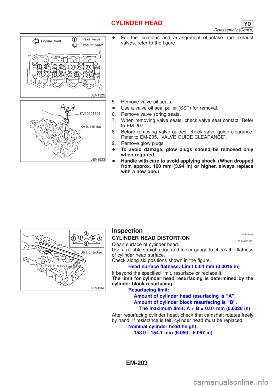
+For the locations and arrangement of intake and exhaust
valves, refer to the figure.
JEM153G
5. Remove valve oil seals.
+Use a valve oil seal puller (SST) for removal.
6. Remove valve spring seats.
7. When removing valve seats, check valve seat contact. Refer
to EM-207.
8. Before removing valve guides, check valve guide clearance.
Refer to EM-205, ªVALVE GUIDE CLEARANCEº.
9. Remove glow plugs.
+To avoid damage, glow plugs should be removed only
when required.
+Handle with care to avoid applying shock. (When dropped
from approx. 100 mm (3.94 in) or higher, always replace
with a new one.)
SEM496G
InspectionNLEM0065CYLINDER HEAD DISTORTIONNLEM0065S01Clean surface of cylinder head.
Use a reliable straightedge and feeler gauge to check the flatness
of cylinder head surface.
Check along six positions shown in the figure.
Head surface flatness: Limit 0.04 mm (0.0016 in)
If beyond the specified limit, resurface or replace it.
The limit for cylinder head resurfacing is determined by the
cylinder block resurfacing.
Resurfacing limit:
Amount of cylinder head resurfacing is ªAº.
Amount of cylinder block resurfacing is ªBº.
The maximum limit: A+ B = 0.07 mm (0.0028 in)
After resurfacing cylinder head, check that camshaft rotates freely
by hand. If resistance is felt, cylinder head must be replaced.
Nominal cylinder head height:
153.9 - 154.1 mm (6.059 - 6.067 in)
CYLINDER HEADYD
Disassembly (Cont'd)
EM-203
Page 2464 of 3051
SEM934C
JEM157G
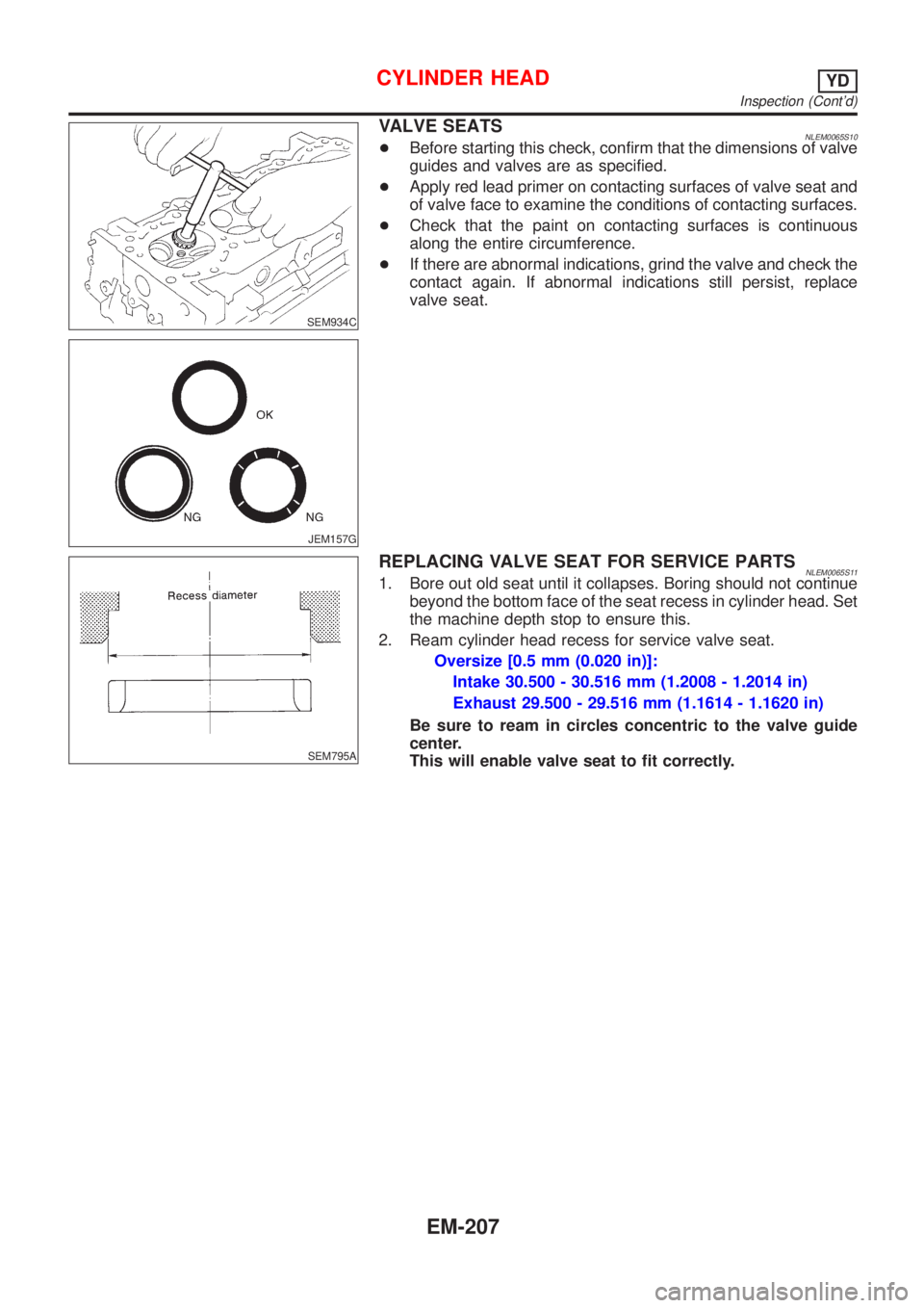
VALVE SEATSNLEM0065S10+Before starting this check, confirm that the dimensions of valve
guides and valves are as specified.
+Apply red lead primer on contacting surfaces of valve seat and
of valve face to examine the conditions of contacting surfaces.
+Check that the paint on contacting surfaces is continuous
along the entire circumference.
+If there are abnormal indications, grind the valve and check the
contact again. If abnormal indications still persist, replace
valve seat.
SEM795A
REPLACING VALVE SEAT FOR SERVICE PARTSNLEM0065S111. Bore out old seat until it collapses. Boring should not continue
beyond the bottom face of the seat recess in cylinder head. Set
the machine depth stop to ensure this.
2. Ream cylinder head recess for service valve seat.
Oversize [0.5 mm (0.020 in)]:
Intake 30.500 - 30.516 mm (1.2008 - 1.2014 in)
Exhaust 29.500 - 29.516 mm (1.1614 - 1.1620 in)
Be sure to ream in circles concentric to the valve guide
center.
This will enable valve seat to fit correctly.
CYLINDER HEADYD
Inspection (Cont'd)
EM-207
Page 2465 of 3051
JEM158G
SEM301G
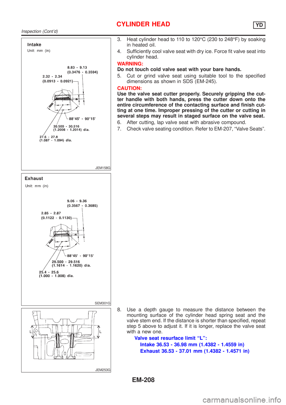
3. Heat cylinder head to 110 to 120ÉC (230 to 248ÉF) by soaking
in heated oil.
4. Sufficiently cool valve seat with dry ice. Force fit valve seat into
cylinder head.
WARNING:
Do not touch cold valve seat with your bare hands.
5. Cut or grind valve seat using suitable tool to the specified
dimensions as shown in SDS (EM-245).
CAUTION:
Use the valve seat cutter properly. Securely gripping the cut-
ter handle with both hands, press the cutter down onto the
entire circumference of the contacting surface and finish cut-
ting at one time. Improper pressing of the cutter or cutting in
several steps may result in staged surface on the valve seat.
6. After cutting, lap valve seat with abrasive compound.
7. Check valve seating condition. Refer to EM-207, ªValve Seatsº.
JEM253G
8. Use a depth gauge to measure the distance between the
mounting surface of the cylinder head spring seat and the
valve stem end. If the distance is shorter than specified, repeat
step 5 above to adjust it. If it is longer, replace the valve seat
with a new one.
Valve seat resurface limit ªLº:
Intake 36.53 - 36.98 mm (1.4382 - 1.4559 in)
Exhaust 36.53 - 37.01 mm (1.4382 - 1.4571 in)
CYLINDER HEADYD
Inspection (Cont'd)
EM-208