2001 NISSAN ALMERA power steering
[x] Cancel search: power steeringPage 1343 of 2898
JEF351Y
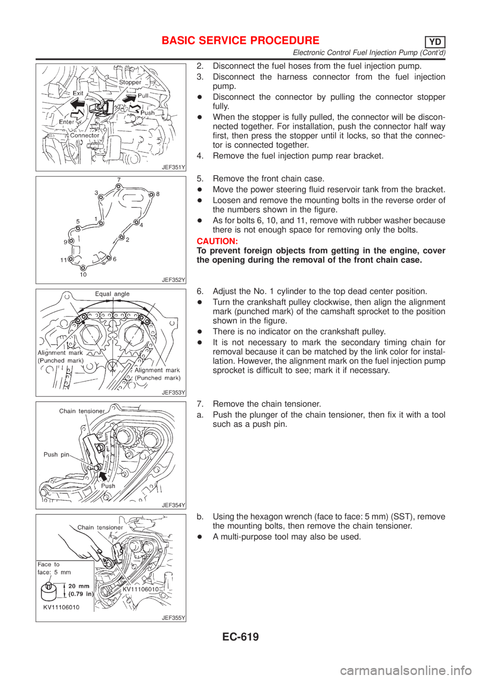
2. Disconnect the fuel hoses from the fuel injection pump.
3. Disconnect the harness connector from the fuel injection
pump.
+Disconnect the connector by pulling the connector stopper
fully.
+When the stopper is fully pulled, the connector will be discon-
nected together. For installation, push the connector half way
first, then press the stopper until it locks, so that the connec-
tor is connected together.
4. Remove the fuel injection pump rear bracket.
JEF352Y
5. Remove the front chain case.
+Move the power steering fluid reservoir tank from the bracket.
+Loosen and remove the mounting bolts in the reverse order of
the numbers shown in the figure.
+As for bolts 6, 10, and 11, remove with rubber washer because
there is not enough space for removing only the bolts.
CAUTION:
To prevent foreign objects from getting in the engine, cover
the opening during the removal of the front chain case.
JEF353Y
6. Adjust the No. 1 cylinder to the top dead center position.
+Turn the crankshaft pulley clockwise, then align the alignment
mark (punched mark) of the camshaft sprocket to the position
shown in the figure.
+There is no indicator on the crankshaft pulley.
+It is not necessary to mark the secondary timing chain for
removal because it can be matched by the link color for instal-
lation. However, the alignment mark on the fuel injection pump
sprocket is difficult to see; mark it if necessary.
JEF354Y
7. Remove the chain tensioner.
a. Push the plunger of the chain tensioner, then fix it with a tool
such as a push pin.
JEF355Y
b. Using the hexagon wrench (face to face: 5 mm) (SST), remove
the mounting bolts, then remove the chain tensioner.
+A multi-purpose tool may also be used.
BASIC SERVICE PROCEDUREYD
Electronic Control Fuel Injection Pump (Cont'd)
EC-619
Page 1559 of 2898
ELECTRICAL SYSTEM
SECTION
EL
CONTENTS
PRECAUTIONS...............................................................5
Supplemental Restraint System (SRS)²AIR
BAG²and²SEAT BELT PRE-TENSIONER²...............5
Wiring Diagrams and Trouble Diagnosis .....................5
HARNESS CONNECTOR................................................6
Description ...................................................................6
STANDARDIZED RELAY................................................8
Description ...................................................................8
POWER SUPPLY ROUTING.........................................10
Schematic/Sedan .......................................................10
Wiring Diagram - POWER -/Sedan With
Gasoline Engine ........................................................ 11
Wiring Diagram - POWER -/Sedan With Diesel
Engine ........................................................................19
Schematic/Hatchback ................................................26
Wiring Diagram - POWER -/Hatchback ....................28
Inspection...................................................................38
GROUND........................................................................39
Ground Distribution ....................................................39
COMBINATION SWITCH..............................................56
Check/Sedan .............................................................56
Check/Hatchback .......................................................57
Replacement ..............................................................58
STEERING SWITCH......................................................59
Check .........................................................................59
HEADLAMP...................................................................60
Wiring Diagram - H/LAMP -/Hatchback.....................60
Wiring Diagram - H/LAMP -/Sedan ...........................61
Trouble Diagnoses.....................................................63
Bulb Replacement .....................................................64
Aiming Adjustment .....................................................65
HEADLAMP - DAYTIME LIGHT SYSTEM -.................67
System Description ....................................................67
Schematic/Sedan .......................................................68
Wiring Diagram - DTRL -/Sedan ...............................69
Schematic/Hatchback ................................................72
Wiring Diagram - DTRL -/Hatchback .........................73
Trouble Diagnoses.....................................................76
Bulb Replacement .....................................................76Aiming Adjustment .....................................................77
HEADLAMP - HEADLAMP AIMING CONTROL -........78
Wiring Diagram - H/AIM -/Sedan...............................78
Wiring Diagram - H/AIM -/Hatchback ........................79
PARKING, LICENSE AND TAIL LAMPS.....................81
Wiring Diagram - TAIL/L -/Sedan ..............................81
Wiring Diagram - TAIL/L -/Hatchback ........................83
STOP LAMP..................................................................85
Wiring Diagram - STOP/L -/Sedan ............................85
Wiring Diagram - STOP/L -/Hatchback .....................86
BACK-UP LAMP............................................................87
Wiring Diagram - BACK/L -/Sedan ............................87
Wiring Diagram - BACK/L -/Hatchback .....................88
FRONT FOG LAMP.......................................................89
Wiring Diagram - F/FOG -/Sedan..............................89
Wiring Diagram - F/FOG -/Hatchback .......................90
Bulb Replacement .....................................................91
Aiming Adjustment .....................................................92
REAR FOG LAMP.........................................................93
Wiring Diagram - R/FOG -/Sedan .............................93
Wiring Diagram - R/FOG -/Hatchback.......................95
TURN SIGNAL AND HAZARD WARNING LAMPS.....96
System Description/Sedan ........................................96
Schematic/Sedan .......................................................98
Wiring Diagram - TURN -/Sedan...............................99
Trouble Diagnoses/Sedan .......................................101
Electrical Components Inspection ...........................101
System Description/Hatchback ................................102
Wiring Diagram - TURN -/Hatchback ......................103
Trouble Diagnoses/Hatchback.................................107
ILLUMINATION............................................................108
Schematic/Sedan .....................................................108
Wiring Diagram - ILL -/Sedan ..................................109
Schematic/Hatchback .............................................. 111
Wiring Diagram - ILL -/Hatchback ........................... 112
INTERIOR ROOM LAMP............................................. 115
System Description/Sedan With Interior Room
Lamp Timer .............................................................. 115
Page 2012 of 2898
for example, when the vehicle is in a tunnel, in a parking lot
inside building, under an elevated superhighway or near strong
power lines, the location may not be detected. Turbulent/
electric weather conditions may also affect positioning perfor-
mance. If something is placed on the antenna, the radio wave
from GPS satellites may not be received.
SEL507X
COMPONENT DESCRIPTIONNJEL0516S02NAVI Control UnitNJEL0516S0201+The gyro (angular speed sensor) and the CD-ROM drive are
built-in units that control the navigation functions.
+Signals are received from the gyro, the vehicle speed sensor,
and the GPS antenna. Vehicle location is determined by com-
bining this data with the data contained in the CD-ROM map.
Locational information is shown on liquid crystal display panel.
SEL506X
CD-ROM DriverNJEL0516S0202Maps, traffic control regulations, and other pertinent information
can be easily red from the CD-ROM disc.
Map CD-ROMNJEL0516S0203+The map CD-ROM has maps, traffic control regulations, and
other pertinent information.
+To improve CD-ROM map matching and route determination
functions, the CD-ROM uses an exclusive Nissan format.
Therefore, the use of a CD-ROM provided by other manufac-
turers cannot be used.
SEL690V
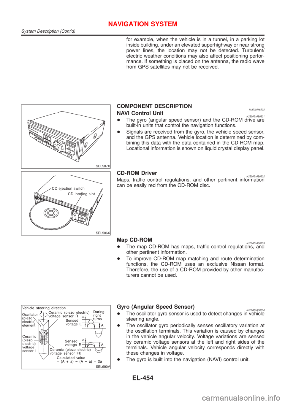
Gyro (Angular Speed Sensor)NJEL0516S0204+The oscillator gyro sensor is used to detect changes in vehicle
steering angle.
+The oscillator gyro periodically senses oscillatory variation at
the oscillation terminals. This variation is caused by changes
in the vehicle angular velocity. Voltage variations are sensed
by ceramic voltage sensors at the left and right sides of the
terminals. Vehicle angular velocity corresponds directly with
these changes in voltage.
+The gyro is built into the navigation (NAVI) control unit.
NAVIGATION SYSTEM
System Description (Cont'd)
EL-454
Page 2134 of 2898
Code Section Wiring Diagram Name
MULTI EL Multi-remote Control System
NATS EL Nissan Anti-Theft System
NAVI EL Navigation System
NONDTC AT Non-detectable Items
O2H1B1 EC Front Heated Oxygen Sensor Heater
(E-OBD)
O2H2B1 EC Rear Heated Oxygen Sensor Heater
(E-OBD)
O2S1B1 EC Front Heated Oxygen Sensor
(E-OBD)
O2S2B1 EC Rear Heated Oxygen Sensor
(E-OBD)
OVRCSV AT Overrun Clutch Solenoid Valve
P/ANT EL Power Antenna
PGC/V EC EVAP Canister Purge Volume Con-
trol Solenoid Valve
PHASE EC Camshaft Position Sensor (PHASE)
PNP/SW EC Park/Neutral Position Switch
PNP/SW AT Park/Neutral Position Switch
POS EC Crankshaft Position Sensor (POS)
POWER EL Power Supply Routing
PST/SW EC Power Steering Oil Pressure Switch
R/FOG EL Rear Fog Lamp
ROOM/L EL Interior Room Lamp
RRO2 EC Rear Heated Oxygen Sensor (Non
E-OBD)
RRO2/H EC Rear Heated Oxygen Sensor Heater
(Non E-OBD)
S/SIG EC Start Signal
SHIFT AT A/T Shift Lock System
S/LOCK EL Power Door Lock Ð Super Lock Ð
SROOF EL Sunroof
SRS RS Supplemental Restraint System
SSV/A AT Shift Solenoid Valve A
SSV/B AT Shift Solenoid Valve B
START SC Starting System
STOP/L EL Stop Lamp
SWL/C EC Swirl Control Valve Control Solenoid
Valve (Non E-OBD)
SWL/V EC Swirl Control Valve Control Solenoid
Valve (E-OBD)
TAIL/L EL Parking, License and Tail LampsCode Section Wiring Diagram Name
TCV AT Torque Converter Clutch Solenoid
Valve
THEFT EL Theft Warning System
TLID EL Trunk Lid Opener
TP/SW EC Throttle Position Switch
TPS AT Throttle Position Sensor
TPS EC Throttle Position Sensor
TURN EL Turn Signal and Hazard Warning
Lamps
VSS EC Vehicle Speed Sensor
VSSA/T AT Vehicle Speed Sensor A/T (Revolu-
tion Sensor)
VSSMTR AT Vehicle Speed Sensor MTR
WARN EL Warning Lamps
WINDOW EL Power Window
WIP/R EL Rear Wiper and Washer
WIPER EL Front Wiper and Washer
WIRING DIAGRAM CODES (CELL CODES)
EL-576
Page 2151 of 2898
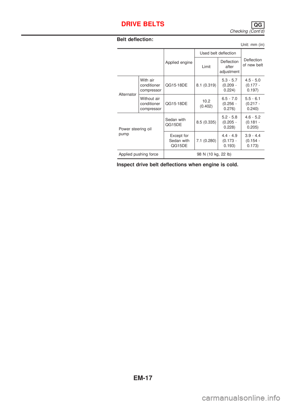
Belt deflection:
Unit: mm (in)
Applied engineUsed belt deflection
Deflection
of new belt
LimitDeflection
after
adjustment
AlternatorWith air
conditioner
compressorQG15´18DE 8.1 (0.319)5.3 - 5.7
(0.209 -
0.224)4.5 - 5.0
(0.177 -
0.197)
Without air
conditioner
compressorQG15´18DE10.2
(0.402)6.5 - 7.0
(0.256 -
0.276)5.5 - 6.1
(0.217 -
0.240)
Power steering oil
pumpSedan with
QG15DE8.5 (0.335)5.2 - 5.8
(0.205 -
0.228)4.6 - 5.2
(0.181 -
0.205)
Except for
Sedan with
QG15DE7.1 (0.280)4.4 - 4.9
(0.173 -
0.193)3.9 - 4.4
(0.154 -
0.173)
Applied pushing force 98 N (10 kg, 22 lb)
Inspect drive belt deflections when engine is cold.
DRIVE BELTSQG
Checking (Cont'd)
EM-17
Page 2158 of 2898
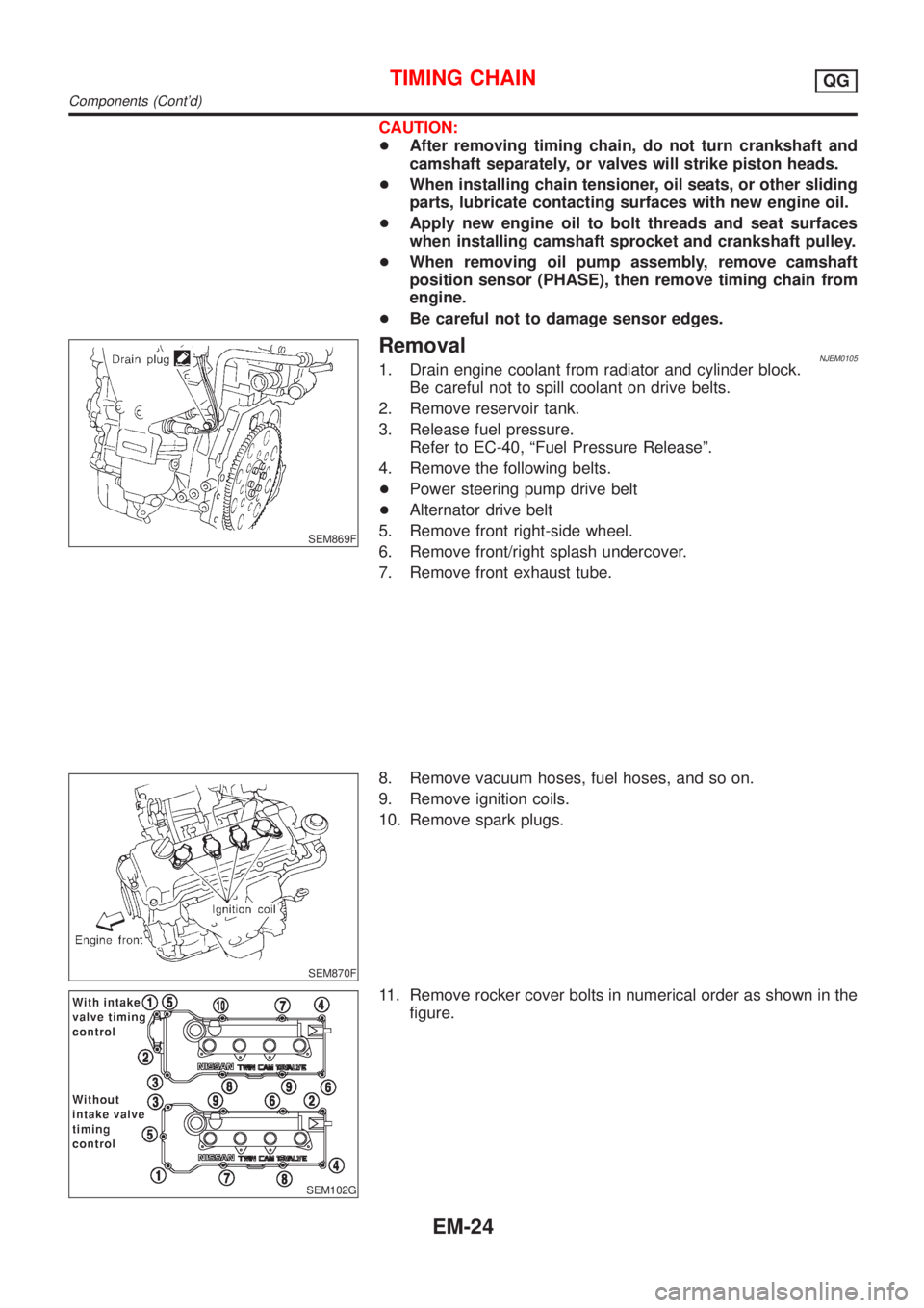
CAUTION:
+After removing timing chain, do not turn crankshaft and
camshaft separately, or valves will strike piston heads.
+When installing chain tensioner, oil seats, or other sliding
parts, lubricate contacting surfaces with new engine oil.
+Apply new engine oil to bolt threads and seat surfaces
when installing camshaft sprocket and crankshaft pulley.
+When removing oil pump assembly, remove camshaft
position sensor (PHASE), then remove timing chain from
engine.
+Be careful not to damage sensor edges.
SEM869F
RemovalNJEM01051. Drain engine coolant from radiator and cylinder block.
Be careful not to spill coolant on drive belts.
2. Remove reservoir tank.
3. Release fuel pressure.
Refer to EC-40, ªFuel Pressure Releaseº.
4. Remove the following belts.
+Power steering pump drive belt
+Alternator drive belt
5. Remove front right-side wheel.
6. Remove front/right splash undercover.
7. Remove front exhaust tube.
SEM870F
8. Remove vacuum hoses, fuel hoses, and so on.
9. Remove ignition coils.
10. Remove spark plugs.
SEM102G
11. Remove rocker cover bolts in numerical order as shown in the
figure.
TIMING CHAINQG
Components (Cont'd)
EM-24
Page 2161 of 2898
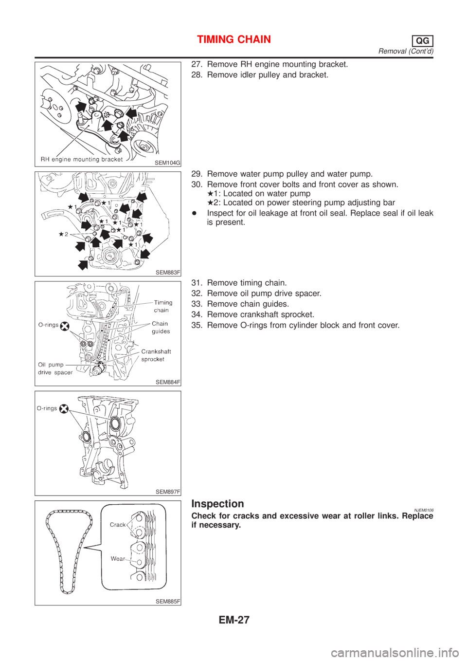
SEM104G
27. Remove RH engine mounting bracket.
28. Remove idler pulley and bracket.
SEM883F
29. Remove water pump pulley and water pump.
30. Remove front cover bolts and front cover as shown.
H1: Located on water pump
H2: Located on power steering pump adjusting bar
+Inspect for oil leakage at front oil seal. Replace seal if oil leak
is present.
SEM884F
SEM897F
31. Remove timing chain.
32. Remove oil pump drive spacer.
33. Remove chain guides.
34. Remove crankshaft sprocket.
35. Remove O-rings from cylinder block and front cover.
SEM885F
InspectionNJEM0106Check for cracks and excessive wear at roller links. Replace
if necessary.
TIMING CHAINQG
Removal (Cont'd)
EM-27
Page 2166 of 2898
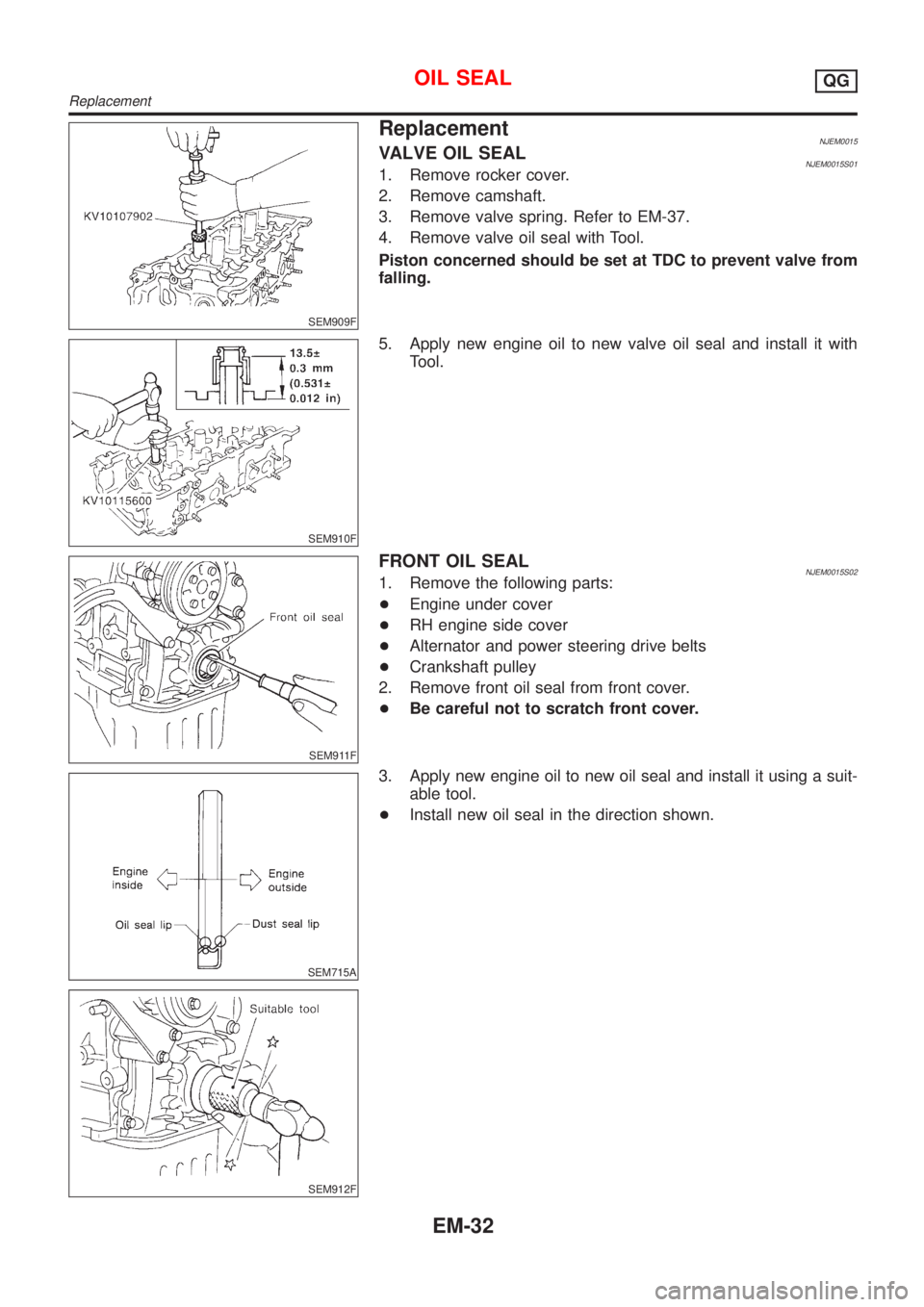
SEM909F
ReplacementNJEM0015VALVE OIL SEALNJEM0015S011. Remove rocker cover.
2. Remove camshaft.
3. Remove valve spring. Refer to EM-37.
4. Remove valve oil seal with Tool.
Piston concerned should be set at TDC to prevent valve from
falling.
SEM910F
5. Apply new engine oil to new valve oil seal and install it with
Tool.
SEM911F
FRONT OIL SEALNJEM0015S021. Remove the following parts:
+Engine under cover
+RH engine side cover
+Alternator and power steering drive belts
+Crankshaft pulley
2. Remove front oil seal from front cover.
+Be careful not to scratch front cover.
SEM715A
SEM912F
3. Apply new engine oil to new oil seal and install it using a suit-
able tool.
+Install new oil seal in the direction shown.
OIL SEALQG
Replacement
EM-32