Page 1039 of 2898
Wiring DiagramNJEC0199
HEC897
DTC P0180 FUEL TANK TEMPERATURE SENSOR (WHERE FITTED)QG
Wiring Diagram
EC-315
Page 1040 of 2898

Diagnostic ProcedureNJEC0200
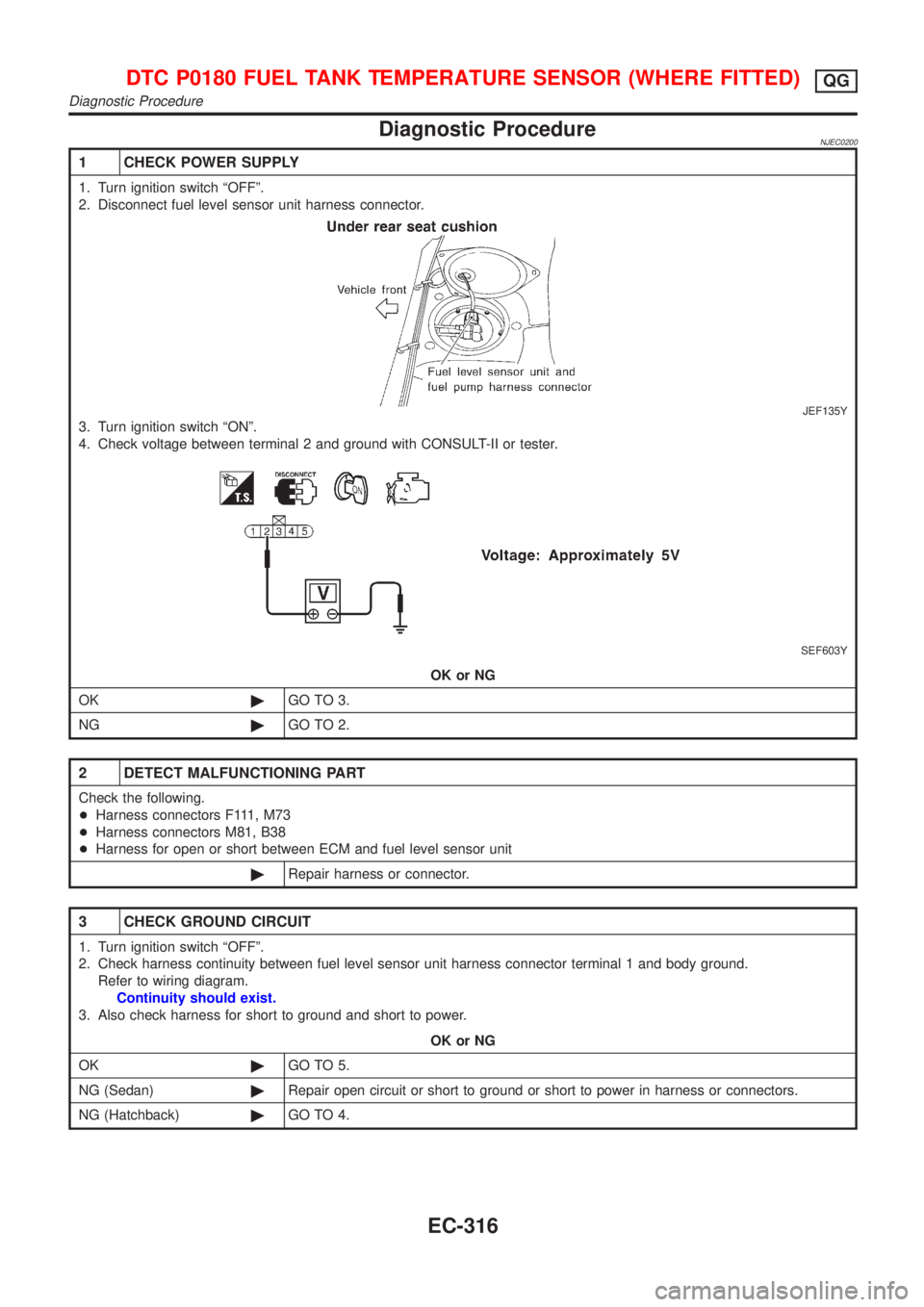
1 CHECK POWER SUPPLY
1. Turn ignition switch ªOFFº.
2. Disconnect fuel level sensor unit harness connector.
JEF135Y
3. Turn ignition switch ªONº.
4. Check voltage between terminal 2 and ground with CONSULT-II or tester.
SEF603Y
OK or NG
OK©GO TO 3.
NG©GO TO 2.
2 DETECT MALFUNCTIONING PART
Check the following.
+Harness connectors F111, M73
+Harness connectors M81, B38
+Harness for open or short between ECM and fuel level sensor unit
©Repair harness or connector.
3 CHECK GROUND CIRCUIT
1. Turn ignition switch ªOFFº.
2. Check harness continuity between fuel level sensor unit harness connector terminal 1 and body ground.
Refer to wiring diagram.
Continuity should exist.
3. Also check harness for short to ground and short to power.
OK or NG
OK©GO TO 5.
NG (Sedan)©Repair open circuit or short to ground or short to power in harness or connectors.
NG (Hatchback)©GO TO 4.
DTC P0180 FUEL TANK TEMPERATURE SENSOR (WHERE FITTED)QG
Diagnostic Procedure
EC-316
Page 1049 of 2898
Wiring DiagramNJEC0210
HEC791
DTC P0325 KNOCK SENSOR (KS)QG
Wiring Diagram
EC-325
Page 1050 of 2898
Diagnostic ProcedureNJEC0211
1 RETIGHTEN GROUND SCREWS
Loosen and retighten engine ground screws.
JEF104Y
©GO TO 2.
2 CHECK INPUT SIGNAL CIRCUIT-1
1. Turn ignition switch ªOFFº.
2. Disconnect ECM harness connector and knock sensor harness connector.
JEF110Y
3. Check harness continuity between knock sensor signal terminal 1 and ECM terminal 81.
Refer to wiring diagram.
Continuity should exist.
4. Also check harness for short to ground and short to power.
OK or NG
OK©GO TO 4.
NG©GO TO 3.
3 DETECT MALFUNCTIONING PART
Check the harness for open or short between knock sensor and ECM.
©Repair open circuit or short to ground or short to power in harness or connectors.
4 CHECK KNOCK SENSOR
Refer to ªComponent Inspectionº, EC-327.
OK or NG
OK©GO TO 5.
NG©Replace knock sensor.
DTC P0325 KNOCK SENSOR (KS)QG
Diagnostic Procedure
EC-326
Page 1054 of 2898
Wiring DiagramNJEC0555SEDAN MODELS AND HATCHBACK MODELS WITH
ECM IN ENGINE COMPARTMENT
NJEC0555S01
HEC792
DTC P0335 CRANKSHAFT POSITION SENSOR (POS)QG
Wiring Diagram
EC-330
Page 1055 of 2898
HATCHBACK MODELS WITH ECM IN CABINNJEC0555S02
HEC974
DTC P0335 CRANKSHAFT POSITION SENSOR (POS)QG
Wiring Diagram (Cont'd)
EC-331
Page 1057 of 2898

3 DETECT MALFUNCTIONING PART
Check the following.
+Joint connector-4 (If so equipped)
+Joint connector-6 (If so equipped)
+Harness connectors E75, F36 (If so equipped)
+Harness for open or short between joint connector and ECM relay
+Harness for open or short between crankshaft position sensor and joint connector
+Harness for open or short between joint connector and ECM
+ECM relay
©Repair open circuit or short to ground or short to power in harness or connectors.
4 CHECK INPUT SIGNAL CIRCUIT
1. Disconnect crankshaft position sensor and ECM harness connectors.
JEF112Y
2. Check continuity between ECM terminal 85 and crankshaft position sensor harness connector terminal 2.
Refer to wiring diagram.
Continuity should exist.
3. Also check harness for short to ground and short to power.
OK or NG
OK©GO TO 5.
NG©Repair open circuit or short to ground or short to power in harness or connectors.
5 CHECK GROUND CIRCUIT
1. Reconnect ECM harness connector.
2. Check harness continuity between terminal 1 and engine ground.
Refer to wiring diagram.
Continuity should exist.
3. Also check harness for short to ground and short to power.
OK or NG
OK©GO TO 6.
NG©Repair open circuit or short to ground or short to power in harness or connectors.
6 CHECK CRANKSHAFT POSITION SENSOR
Refer to ªComponent Inspectionº, EC-334.
OK or NG
OK©GO TO 7.
NG©Replace crankshaft position sensor.
7 CHECK INTERMITTENT INCIDENT
Perform ªTROUBLE DIAGNOSIS FOR INTERMITTENT INCIDENTº, EC-177.
©INSPECTION END
DTC P0335 CRANKSHAFT POSITION SENSOR (POS)QG
Diagnostic Procedure (Cont'd)
EC-333
Page 1061 of 2898
Wiring DiagramNJEC0224SEDAN MODELS AND HATCHBACK MODELS WITH
ECM IN ENGINE COMPARTMENT
NJEC0224S01
HEC793
DTC P0340 CAMSHAFT POSITION SENSOR (CMPS) (PHASE)QG
Wiring Diagram
EC-337