Page 52 of 2493

NJGI0011
ISO 15031-2NJGI0011S01All emission related terms used in this publication in accordance with ISO 15031-2 are listed. Accordingly, new
terms, new acronyms/abbreviations and old terms are listed in the following chart.
***: Not applicable
NEW TERMNEW ACRONYM /
ABBREVIATIONOLD TERM
Air cleaner ACL Air cleaner
Barometric pressure sensor BARO sensor ***
Barometric pressure sensor-BCDD BAROS-BCDD BCDD
Camshaft position CMP ***
Camshaft position sensor CMPS Crank angle sensor
Canister *** Canister
Carburetor CARB Carburetor
Charge air cooler CAC Intercooler
Closed loop CL Closed loop
Closed throttle position switch CTP switch Idle switch
Clutch pedal position switch CPP switch Clutch switch
Continuous fuel injection system CFI system ***
Continuous trap oxidizer system CTOX system ***
Crankshaft position CKP ***
Crankshaft position sensor CKPS ***
Data link connector DLC Diagnostic connector for CONSULT
Diagnostic test mode DTM Diagnostic mode
Diagnostic test mode selector DTM selector Diagnostic mode selector
Diagnostic test mode I DTM I Mode I
Diagnostic test mode II DTM II Mode II
Diagnostic trouble code DTC Malfunction code
Direct fuel injection system DFI system ***
Distributor ignition system DI system Ignition timing control
Early fuel evaporation-mixture heater EFE-mixture heater Mixture heater
Early fuel evaporation system EFE system Mixture heater control
Electrically erasable programmable read
only memoryEEPROM ***
Electronic ignition system EI system Ignition timing control
Engine control EC ***
Engine control module ECM ECCS control unit
Engine coolant temperature ECT Engine temperature
Engine coolant temperature sensor ECTS Engine temperature sensor
Engine modification EM ***
Engine speed RPM Engine speed
ISO 15031-2 TERMINOLOGY LIST
ISO 15031-2
GI-50
Page 100 of 2493
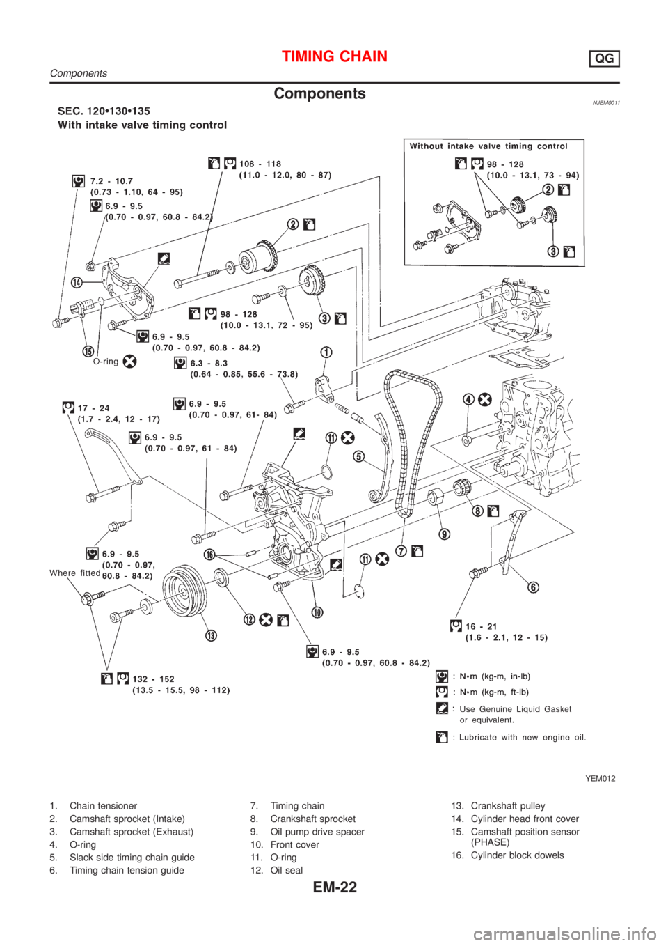
ComponentsNJEM0011
YEM012
1. Chain tensioner
2. Camshaft sprocket (Intake)
3. Camshaft sprocket (Exhaust)
4. O-ring
5. Slack side timing chain guide
6. Timing chain tension guide7. Timing chain
8. Crankshaft sprocket
9. Oil pump drive spacer
10. Front cover
11. O-ring
12. Oil seal13. Crankshaft pulley
14. Cylinder head front cover
15. Camshaft position sensor
(PHASE)
16. Cylinder block dowels
TIMING CHAINQG
Components
EM-22
Page 101 of 2493
CAUTION:
+After removing timing chain, do not turn crankshaft and
camshaft separately, or valves will strike piston heads.
+When installing chain tensioner, oil seats, or other sliding
parts, lubricate contacting surfaces with new engine oil.
+Apply new engine oil to bolt threads and seat surfaces
when installing camshaft sprocket and crankshaft pulley.
+When removing oil pump assembly, remove camshaft
position sensor (PHASE), then remove timing chain from
engine.
+Be careful not to damage sensor edges.
SEM869F
RemovalNJEM01051. Drain engine coolant from radiator and cylinder block.
Be careful not to spill coolant on drive belts.
2. Remove reservoir tank.
3. Release fuel pressure.
Refer to EC-38, ªFuel Pressure Releaseº.
4. Remove the following belts.
+Power steering pump drive belt
+Alternator drive belt
5. Remove front right-side wheel.
6. Remove front/right splash undercover.
7. Remove front exhaust tube.
SEM870F
8. Remove vacuum hoses, fuel hoses, and so on.
9. Remove ignition coils.
10. Remove spark plugs.
SEM102G
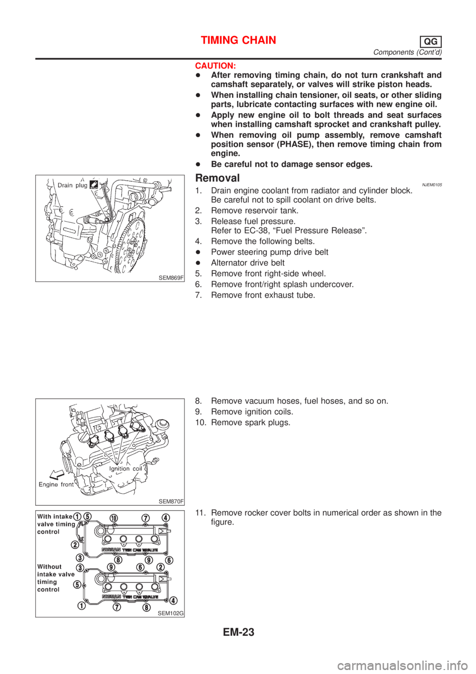
11. Remove rocker cover bolts in numerical order as shown in the
figure.
TIMING CHAINQG
Components (Cont'd)
EM-23
Page 102 of 2493
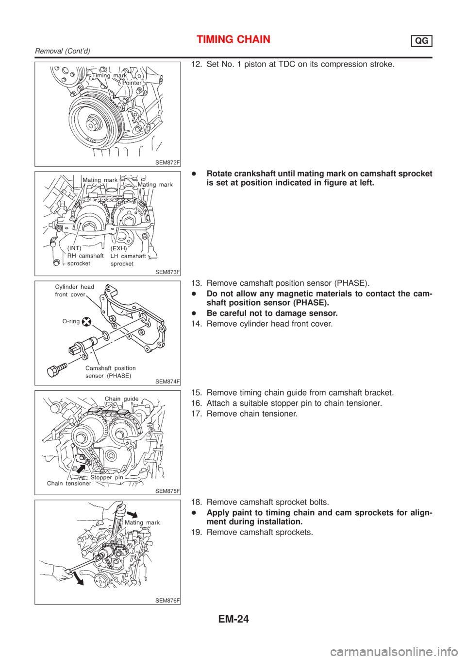
SEM872F
12. Set No. 1 piston at TDC on its compression stroke.
SEM873F
+Rotate crankshaft until mating mark on camshaft sprocket
is set at position indicated in figure at left.
SEM874F
13. Remove camshaft position sensor (PHASE).
+Do not allow any magnetic materials to contact the cam-
shaft position sensor (PHASE).
+Be careful not to damage sensor.
14. Remove cylinder head front cover.
SEM875F
15. Remove timing chain guide from camshaft bracket.
16. Attach a suitable stopper pin to chain tensioner.
17. Remove chain tensioner.
SEM876F
18. Remove camshaft sprocket bolts.
+Apply paint to timing chain and cam sprockets for align-
ment during installation.
19. Remove camshaft sprockets.
TIMING CHAINQG
Removal (Cont'd)
EM-24
Page 113 of 2493
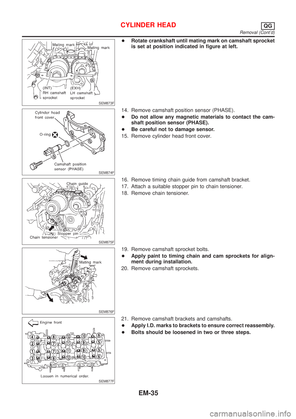
SEM873F
+Rotate crankshaft until mating mark on camshaft sprocket
is set at position indicated in figure at left.
SEM874F
14. Remove camshaft position sensor (PHASE).
+Do not allow any magnetic materials to contact the cam-
shaft position sensor (PHASE).
+Be careful not to damage sensor.
15. Remove cylinder head front cover.
SEM875F
16. Remove timing chain guide from camshaft bracket.
17. Attach a suitable stopper pin to chain tensioner.
18. Remove chain tensioner.
SEM876F
19. Remove camshaft sprocket bolts.
+Apply paint to timing chain and cam sprockets for align-
ment during installation.
20. Remove camshaft sprockets.
SEM877F
21. Remove camshaft brackets and camshafts.
+Apply I.D. marks to brackets to ensure correct reassembly.
+Bolts should be loosened in two or three steps.
CYLINDER HEADQG
Removal (Cont'd)
EM-35
Page 128 of 2493

WARNING:
+Position vehicle on a flat and solid surface.
+Place chocks at front and back of rear wheels.
+Do not remove engine until exhaust system has com-
pletely cooled off, otherwise, you may burn yourself
and/or fire may break out in fuel line.
+Before disconnecting fuel hose, release pressure.
Refer to EC-38, ªFuel Pressure Releaseº.
+Be sure to lift engine and transaxle in a safe manner.
+For engines not equipped with engine slingers, attach
proper slingers and bolts described in PARTS CATALOG.
CAUTION:
+When lifting engine, be sure to clear surrounding parts.
Use special care near accelerator wire casing, brake lines
and brake master cylinder.
+When lifting the engine, always use engine slingers in a
safe manner.
+When removing drive shaft, be careful not to damage
grease seal of transaxle.
+Before separating engine and transaxle, remove crank-
shaft position sensor (POS) from the cylinder block
assembly.
+Always be extra careful not to damage edge of crankshaft
position sensor (POS), or signal plate teeth.
Engine cannot be removed separately from transaxle. Remove
engine with transaxle as an assembly.
REMOVALNJEM0022S011. Drain coolant from radiator and cylinder block. Refer to LC-17,
ªChanging Engine Coolantº.
2. Remove coolant reservoir tank and bracket.
3. Drain engine oil.
4. Remove battery and battery tray.
5. Remove air cleaner and air duct.
6. Remove drive belts.
7. Remove alternator and air conditioner compressor from
engine.
8. Remove power steering oil pump from engine and position
aside.
Power steering oil pump does not need to be disconnected
from power steering tubes.
ENGINE ASSEMBLYQG
Removal and Installation (Cont'd)
EM-50
Page 130 of 2493
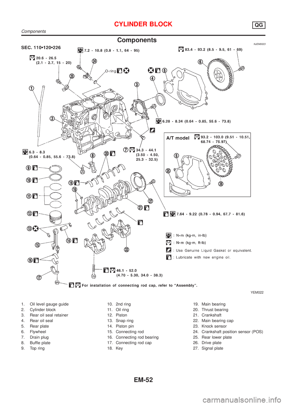
ComponentsNJEM0023
YEM022
1. Oil level gauge guide
2. Cylinder block
3. Rear oil seal retainer
4. Rear oil seal
5. Rear plate
6. Flywheel
7. Drain plug
8. Buffle plate
9. Top ring10. 2nd ring
11. Oil ring
12. Piston
13. Snap ring
14. Piston pin
15. Connecting rod
16. Connecting rod bearing
17. Connecting rod cap
18. Key19. Main bearing
20. Thrust bearing
21. Crankshaft
22. Main bearing cap
23. Knock sensor
24. Crankshaft position sensor (POS)
25. Rear lower plate
26. Drive plate
27. Signal plate
CYLINDER BLOCKQG
Components
EM-52
Page 131 of 2493

Removal and InstallationNJEM0024CAUTION:
+When installing sliding parts such as bearings and
pistons, apply engine oil on the sliding surfaces.
+Place removed parts, such as bearings and bearing caps,
in their proper order and direction.
+When installing connecting rod nuts and main bearing cap
bolts, apply new engine oil to threads and seating sur-
faces.
+Do not allow any magnetic materials to contact the signal
plate teeth of flywheel or drive plate, and rear plate.
+Remove the crankshaft position sensor (POS).
+Be careful not to damage sensor edges and single plate
teeth.
SEM927F
DisassemblyNJEM0025PISTON AND CRANKSHAFTNJEM0025S011. Place engine on a work stand.
2. Drain coolant and oil.
3. Remove timing chain.
Refer to EM-23.
SEM877B
4. Remove pistons with connecting rod.
+When disassembling piston and connecting rod, remove snap
ring first. Then heat piston to 60 to 70ÉC (140 to 158ÉF) or use
piston pin press stand at room temperature.
CAUTION:
+When piston rings are not replaced, make sure that piston
rings are mounted in their original positions.
+When replacing piston rings, if there is no punch mark,
install with either side up.
SEM165DB
5. Loosen main bearing caps in numerical order as shown in fig-
ure.
6. Remove bearing caps, main bearings and crankshaft.
+Before removing bearing caps, measure crankshaft end
play. Refer to EM-61.
+Bolts should be loosened in two or three steps.
CYLINDER BLOCKQG
Removal and Installation
EM-53