2001 NISSAN ALMERA N16 Coolant temperature sensor
[x] Cancel search: Coolant temperature sensorPage 52 of 2493

NJGI0011
ISO 15031-2NJGI0011S01All emission related terms used in this publication in accordance with ISO 15031-2 are listed. Accordingly, new
terms, new acronyms/abbreviations and old terms are listed in the following chart.
***: Not applicable
NEW TERMNEW ACRONYM /
ABBREVIATIONOLD TERM
Air cleaner ACL Air cleaner
Barometric pressure sensor BARO sensor ***
Barometric pressure sensor-BCDD BAROS-BCDD BCDD
Camshaft position CMP ***
Camshaft position sensor CMPS Crank angle sensor
Canister *** Canister
Carburetor CARB Carburetor
Charge air cooler CAC Intercooler
Closed loop CL Closed loop
Closed throttle position switch CTP switch Idle switch
Clutch pedal position switch CPP switch Clutch switch
Continuous fuel injection system CFI system ***
Continuous trap oxidizer system CTOX system ***
Crankshaft position CKP ***
Crankshaft position sensor CKPS ***
Data link connector DLC Diagnostic connector for CONSULT
Diagnostic test mode DTM Diagnostic mode
Diagnostic test mode selector DTM selector Diagnostic mode selector
Diagnostic test mode I DTM I Mode I
Diagnostic test mode II DTM II Mode II
Diagnostic trouble code DTC Malfunction code
Direct fuel injection system DFI system ***
Distributor ignition system DI system Ignition timing control
Early fuel evaporation-mixture heater EFE-mixture heater Mixture heater
Early fuel evaporation system EFE system Mixture heater control
Electrically erasable programmable read
only memoryEEPROM ***
Electronic ignition system EI system Ignition timing control
Engine control EC ***
Engine control module ECM ECCS control unit
Engine coolant temperature ECT Engine temperature
Engine coolant temperature sensor ECTS Engine temperature sensor
Engine modification EM ***
Engine speed RPM Engine speed
ISO 15031-2 TERMINOLOGY LIST
ISO 15031-2
GI-50
Page 91 of 2493

YEM021
1. Crankshaft pulley
2. Engine coolant temperature sen-
sor
3. Gasket
4. Exhaust manifold5. Exhaust manifold cover
6. Thermal transmitter
7. Water drain plug
8. Heated oxygen sensor 1 (front)
9. Three way catalyst10. Converter cap
11. Converter cover
12. Ignition coil
13. Spark plug
OUTER COMPONENT PARTSQG
Removal and Installation (Cont'd)
EM-13
Page 131 of 2493

Removal and InstallationNJEM0024CAUTION:
+When installing sliding parts such as bearings and
pistons, apply engine oil on the sliding surfaces.
+Place removed parts, such as bearings and bearing caps,
in their proper order and direction.
+When installing connecting rod nuts and main bearing cap
bolts, apply new engine oil to threads and seating sur-
faces.
+Do not allow any magnetic materials to contact the signal
plate teeth of flywheel or drive plate, and rear plate.
+Remove the crankshaft position sensor (POS).
+Be careful not to damage sensor edges and single plate
teeth.
SEM927F
DisassemblyNJEM0025PISTON AND CRANKSHAFTNJEM0025S011. Place engine on a work stand.
2. Drain coolant and oil.
3. Remove timing chain.
Refer to EM-23.
SEM877B
4. Remove pistons with connecting rod.
+When disassembling piston and connecting rod, remove snap
ring first. Then heat piston to 60 to 70ÉC (140 to 158ÉF) or use
piston pin press stand at room temperature.
CAUTION:
+When piston rings are not replaced, make sure that piston
rings are mounted in their original positions.
+When replacing piston rings, if there is no punch mark,
install with either side up.
SEM165DB
5. Loosen main bearing caps in numerical order as shown in fig-
ure.
6. Remove bearing caps, main bearings and crankshaft.
+Before removing bearing caps, measure crankshaft end
play. Refer to EM-61.
+Bolts should be loosened in two or three steps.
CYLINDER BLOCKQG
Removal and Installation
EM-53
Page 298 of 2493
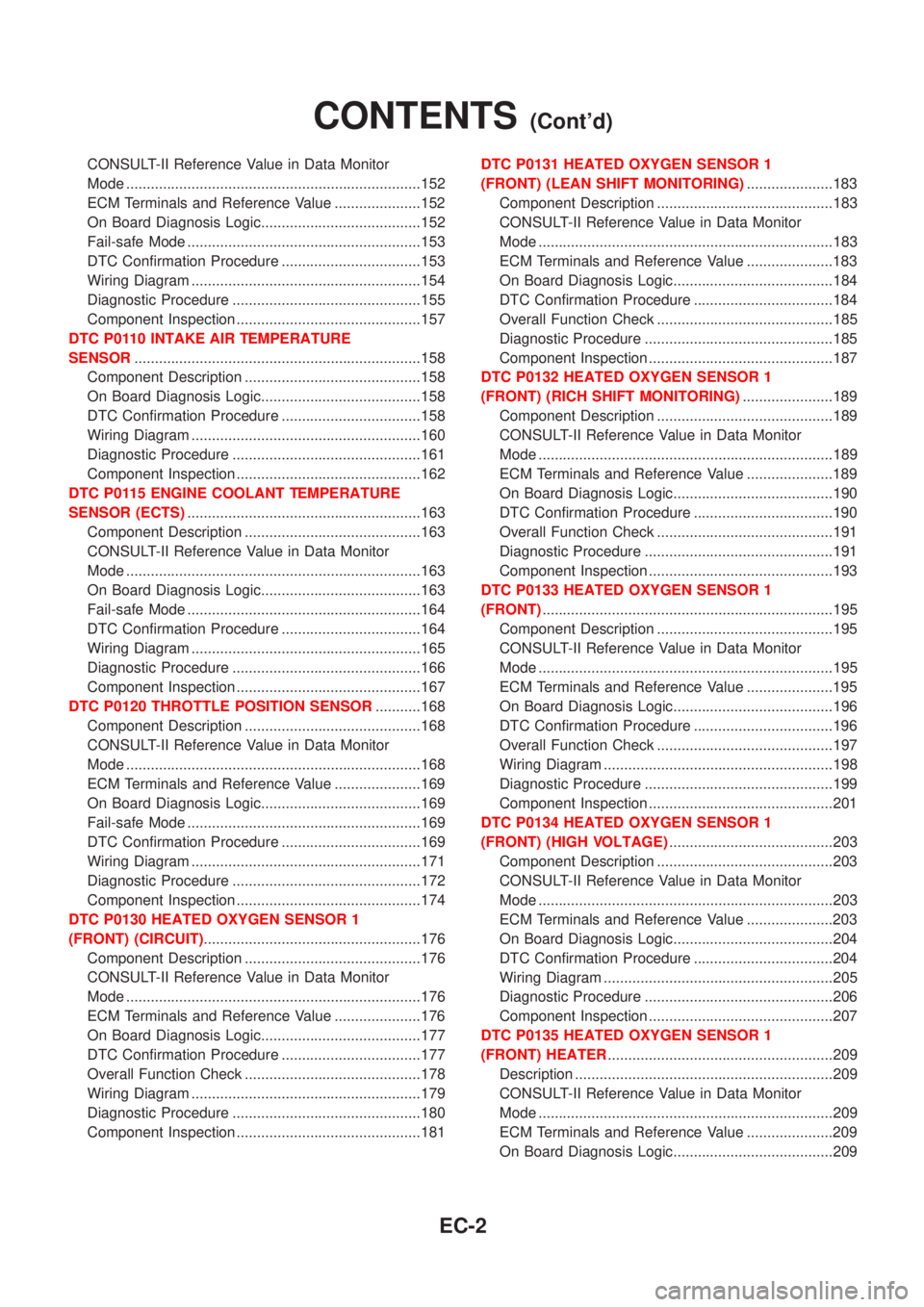
CONSULT-II Reference Value in Data Monitor
Mode ........................................................................152
ECM Terminals and Reference Value .....................152
On Board Diagnosis Logic.......................................152
Fail-safe Mode .........................................................153
DTC Confirmation Procedure ..................................153
Wiring Diagram ........................................................154
Diagnostic Procedure ..............................................155
Component Inspection .............................................157
DTC P0110 INTAKE AIR TEMPERATURE
SENSOR......................................................................158
Component Description ...........................................158
On Board Diagnosis Logic.......................................158
DTC Confirmation Procedure ..................................158
Wiring Diagram ........................................................160
Diagnostic Procedure ..............................................161
Component Inspection .............................................162
DTC P0115 ENGINE COOLANT TEMPERATURE
SENSOR (ECTS).........................................................163
Component Description ...........................................163
CONSULT-II Reference Value in Data Monitor
Mode ........................................................................163
On Board Diagnosis Logic.......................................163
Fail-safe Mode .........................................................164
DTC Confirmation Procedure ..................................164
Wiring Diagram ........................................................165
Diagnostic Procedure ..............................................166
Component Inspection .............................................167
DTC P0120 THROTTLE POSITION SENSOR...........168
Component Description ...........................................168
CONSULT-II Reference Value in Data Monitor
Mode ........................................................................168
ECM Terminals and Reference Value .....................169
On Board Diagnosis Logic.......................................169
Fail-safe Mode .........................................................169
DTC Confirmation Procedure ..................................169
Wiring Diagram ........................................................171
Diagnostic Procedure ..............................................172
Component Inspection .............................................174
DTC P0130 HEATED OXYGEN SENSOR 1
(FRONT) (CIRCUIT).....................................................176
Component Description ...........................................176
CONSULT-II Reference Value in Data Monitor
Mode ........................................................................176
ECM Terminals and Reference Value .....................176
On Board Diagnosis Logic.......................................177
DTC Confirmation Procedure ..................................177
Overall Function Check ...........................................178
Wiring Diagram ........................................................179
Diagnostic Procedure ..............................................180
Component Inspection .............................................181DTC P0131 HEATED OXYGEN SENSOR 1
(FRONT) (LEAN SHIFT MONITORING).....................183
Component Description ...........................................183
CONSULT-II Reference Value in Data Monitor
Mode ........................................................................183
ECM Terminals and Reference Value .....................183
On Board Diagnosis Logic.......................................184
DTC Confirmation Procedure ..................................184
Overall Function Check ...........................................185
Diagnostic Procedure ..............................................185
Component Inspection .............................................187
DTC P0132 HEATED OXYGEN SENSOR 1
(FRONT) (RICH SHIFT MONITORING)......................189
Component Description ...........................................189
CONSULT-II Reference Value in Data Monitor
Mode ........................................................................189
ECM Terminals and Reference Value .....................189
On Board Diagnosis Logic.......................................190
DTC Confirmation Procedure ..................................190
Overall Function Check ...........................................191
Diagnostic Procedure ..............................................191
Component Inspection .............................................193
DTC P0133 HEATED OXYGEN SENSOR 1
(FRONT).......................................................................195
Component Description ...........................................195
CONSULT-II Reference Value in Data Monitor
Mode ........................................................................195
ECM Terminals and Reference Value .....................195
On Board Diagnosis Logic.......................................196
DTC Confirmation Procedure ..................................196
Overall Function Check ...........................................197
Wiring Diagram ........................................................198
Diagnostic Procedure ..............................................199
Component Inspection .............................................201
DTC P0134 HEATED OXYGEN SENSOR 1
(FRONT) (HIGH VOLTAGE)........................................203
Component Description ...........................................203
CONSULT-II Reference Value in Data Monitor
Mode ........................................................................203
ECM Terminals and Reference Value .....................203
On Board Diagnosis Logic.......................................204
DTC Confirmation Procedure ..................................204
Wiring Diagram ........................................................205
Diagnostic Procedure ..............................................206
Component Inspection .............................................207
DTC P0135 HEATED OXYGEN SENSOR 1
(FRONT) HEATER.......................................................209
Description ...............................................................209
CONSULT-II Reference Value in Data Monitor
Mode ........................................................................209
ECM Terminals and Reference Value .....................209
On Board Diagnosis Logic.......................................209
CONTENTS(Cont'd)
EC-2
Page 302 of 2493
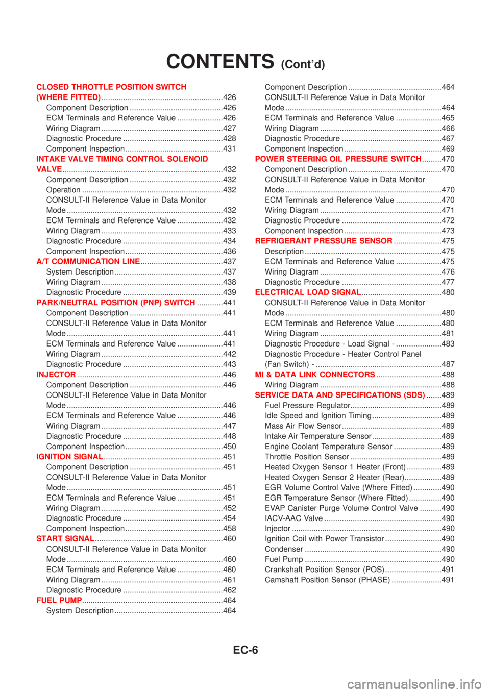
CLOSED THROTTLE POSITION SWITCH
(WHERE FITTED)........................................................426
Component Description ...........................................426
ECM Terminals and Reference Value .....................426
Wiring Diagram ........................................................427
Diagnostic Procedure ..............................................428
Component Inspection .............................................431
INTAKE VALVE TIMING CONTROL SOLENOID
VALVE..........................................................................432
Component Description ...........................................432
Operation .................................................................432
CONSULT-II Reference Value in Data Monitor
Mode ........................................................................432
ECM Terminals and Reference Value .....................432
Wiring Diagram ........................................................433
Diagnostic Procedure ..............................................434
Component Inspection .............................................436
A/T COMMUNICATION LINE......................................437
System Description ..................................................437
Wiring Diagram ........................................................438
Diagnostic Procedure ..............................................439
PARK/NEUTRAL POSITION (PNP) SWITCH............441
Component Description ...........................................441
CONSULT-II Reference Value in Data Monitor
Mode ........................................................................441
ECM Terminals and Reference Value .....................441
Wiring Diagram ........................................................442
Diagnostic Procedure ..............................................443
INJECTOR...................................................................446
Component Description ...........................................446
CONSULT-II Reference Value in Data Monitor
Mode ........................................................................446
ECM Terminals and Reference Value .....................446
Wiring Diagram ........................................................447
Diagnostic Procedure ..............................................448
Component Inspection .............................................450
IGNITION SIGNAL.......................................................451
Component Description ...........................................451
CONSULT-II Reference Value in Data Monitor
Mode ........................................................................451
ECM Terminals and Reference Value .....................451
Wiring Diagram ........................................................452
Diagnostic Procedure ..............................................454
Component Inspection .............................................458
START SIGNAL...........................................................460
CONSULT-II Reference Value in Data Monitor
Mode ........................................................................460
ECM Terminals and Reference Value .....................460
Wiring Diagram ........................................................461
Diagnostic Procedure ..............................................462
FUEL PUMP.................................................................464
System Description ..................................................464Component Description ...........................................464
CONSULT-II Reference Value in Data Monitor
Mode ........................................................................464
ECM Terminals and Reference Value .....................465
Wiring Diagram ........................................................466
Diagnostic Procedure ..............................................467
Component Inspection .............................................469
POWER STEERING OIL PRESSURE SWITCH.........470
Component Description ...........................................470
CONSULT-II Reference Value in Data Monitor
Mode ........................................................................470
ECM Terminals and Reference Value .....................470
Wiring Diagram ........................................................471
Diagnostic Procedure ..............................................472
Component Inspection .............................................473
REFRIGERANT PRESSURE SENSOR......................475
Description ...............................................................475
ECM Terminals and Reference Value .....................475
Wiring Diagram ........................................................476
Diagnostic Procedure ..............................................477
ELECTRICAL LOAD SIGNAL.....................................480
CONSULT-II Reference Value in Data Monitor
Mode ........................................................................480
ECM Terminals and Reference Value .....................480
Wiring Diagram ........................................................481
Diagnostic Procedure - Load Signal - .....................483
Diagnostic Procedure - Heater Control Panel
(Fan Switch) - ..........................................................487
MI & DATA LINK CONNECTORS..............................488
Wiring Diagram ........................................................488
SERVICE DATA AND SPECIFICATIONS (SDS).......489
Fuel Pressure Regulator..........................................489
Idle Speed and Ignition Timing ................................489
Mass Air Flow Sensor..............................................489
Intake Air Temperature Sensor ................................489
Engine Coolant Temperature Sensor ......................489
Throttle Position Sensor ..........................................489
Heated Oxygen Sensor 1 Heater (Front) ................489
Heated Oxygen Sensor 2 Heater (Rear).................489
EGR Volume Control Valve (Where Fitted) .............490
EGR Temperature Sensor (Where Fitted) ...............490
EVAP Canister Purge Volume Control Valve ..........490
IACV-AAC Valve ......................................................490
Injector .....................................................................490
Ignition Coil with Power Transistor ..........................490
Condenser ...............................................................490
Fuel Pump ...............................................................490
Crankshaft Position Sensor (POS) ..........................491
Camshaft Position Sensor (PHASE) .......................491
CONTENTS(Cont'd)
EC-6
Page 305 of 2493
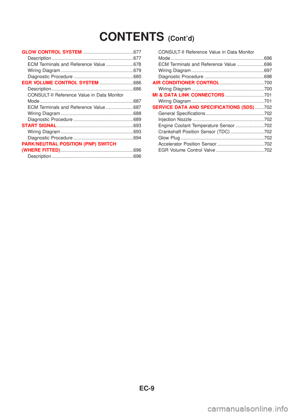
GLOW CONTROL SYSTEM.......................................677
Description ...............................................................677
ECM Terminals and Reference Value .....................678
Wiring Diagram ........................................................679
Diagnostic Procedure ..............................................680
EGR VOLUME CONTROL SYSTEM..........................686
Description ...............................................................686
CONSULT-II Reference Value in Data Monitor
Mode ........................................................................687
ECM Terminals and Reference Value .....................687
Wiring Diagram ........................................................688
Diagnostic Procedure ..............................................689
START SIGNAL...........................................................693
Wiring Diagram ........................................................693
Diagnostic Procedure ..............................................694
PARK/NEUTRAL POSITION (PNP) SWITCH
(WHERE FITTED)........................................................696
Description ...............................................................696CONSULT-II Reference Value in Data Monitor
Mode ........................................................................696
ECM Terminals and Reference Value .....................696
Wiring Diagram ........................................................697
Diagnostic Procedure ..............................................698
AIR CONDITIONER CONTROL..................................700
Wiring Diagram ........................................................700
MI & DATA LINK CONNECTORS..............................701
Wiring Diagram ........................................................701
SERVICE DATA AND SPECIFICATIONS (SDS).......702
General Specifications .............................................702
Injection Nozzle .......................................................702
Engine Coolant Temperature Sensor ......................702
Crankshaft Position Sensor (TDC) ..........................702
Glow Plug ................................................................702
Accelerator Position Sensor ....................................702
EGR Volume Control Valve .....................................702
CONTENTS(Cont'd)
EC-9
Page 324 of 2493

System ChartNJEC0013
Input (Sensor) ECM Function Output (Actuator)
+Camshaft position sensor (PHASE)
+Crankshaft position sensor (POS)
+Mass air flow sensor
+Engine coolant temperature sensor
+Heated oxygen sensor 1 (front)
+Ignition switch
+Throttle position sensor
+PNP switch
+Air conditioner switch
+Knock sensor
+EGR temperature sensor*1, *4
+Battery voltage
+Power steering oil pressure switch
+Vehicle speed sensor
+Intake air temperature sensor
+Heated oxygen sensor 2 (rear)*2
+TCM (Transmission Control Module)*3
+Closed throttle position switch
+Electrical load
+Refrigerant pressure sensorFuel injection & mixture ratio control Injectors
Electronic ignition system Power transistor
Idle air control system IACV-AAC valve
Intake valve timing controlIntake valve timing control sole-
noid valve
Fuel pump control Fuel pump relay
On board diagnostic systemMalfunction indicator
(On the instrument panel)
EGR control*4 EGR volume control valve*4
Heated oxygen sensor 1/2 heater (front/
rear) controlHeated oxygen sensor 1/2 heater
(front/rear)
EVAP canister purge flow controlEVAP canister purge volume con-
trol solenoid valve
Cooling fan control Cooling fan relay
Air conditioning cut control Air conditioner relay
*1: These sensors are not used to control the engine system. They are used only for the on board diagnosis.
*2: Under normal conditions, this sensor is not for engine control operation.
*3: The DTC related to A/T will be sent to ECM.
*4: If so equipped
ENGINE AND EMISSION CONTROL OVERALL SYSTEMQG
System Chart
EC-28
Page 325 of 2493

Multiport Fuel Injection (MFI) System
DESCRIPTIONNJEC0014Input/Output Signal ChartNJEC0014S01
Sensor Input Signal to ECMECM func-
tionActuator
Crankshaft position sensor (POS) Engine speed
Fuel injec-
tion & mix-
ture ratio
controlInjector Camshaft position sensor (PHASE) Engine speed and cylinder number
Mass air flow sensor Amount of intake air
Engine coolant temperature sensor Engine coolant temperature
Heated oxygen sensor 1 (front) Density of oxygen in exhaust gas
Throttle position sensorThrottle position
Throttle valve idle position
PNP switch Gear position
Vehicle speed sensor Vehicle speed
Ignition switch Start signal
Air conditioner switch Air conditioner operation
Knock sensor Engine knocking condition
Electrical load Electrical load signal
Battery Battery voltage
Power steering oil pressure switch Power steering operation
Heated oxygen sensor 2 (rear)* Density of oxygen in exhaust gas
* Under normal conditions, this sensor is not for engine control operation.
Basic Multiport Fuel Injection SystemNJEC0014S02The amount of fuel injected from the fuel injector is determined by the ECM. The ECM controls the length of
time the valve remains open (injection pulse duration). The amount of fuel injected is a program value in the
ECM memory. The program value is preset by engine operating conditions. These conditions are determined
by input signals (for engine speed and intake air) from both the camshaft position sensor and the mass air
flow sensor.
Various Fuel Injection Increase/Decrease CompensationNJEC0014S03In addition, the amount of fuel injected is compensated to improve engine performance under various oper-
ating conditions as listed below.
+During warm-up
+When starting the engine
+During acceleration
+Hot-engine operation
+When selector lever is changed from ªNº to ªDº (A/T models)
+High-load, high-speed operation
+During deceleration
+During high engine speed operation
+During high vehicle speed operation (M/T models)
+Extremely high engine coolant temperature
ENGINE AND EMISSION BASIC CONTROL SYSTEM DESCRIPTIONQG
Multiport Fuel Injection (MFI) System
EC-29