Page 1136 of 2493
SMT737DA
Transaxle CaseNJMT0067S021. Insert differential oil seal into differential case until it becomes
flush with case end face.
SMT739D
2. Install welch plug into transaxle case.
SMT740D
3. Calculate dimension ªNº (thickness of adjusting shim) using
the following procedure to satisfy specification of end play for
differential side bearing.
End play: 0.15 - 0.21 mm (0.0059 - 0.0083 in)
Dimension ªNº = (N1 ± N2) + End play
N: Thickness of adjusting shim
N1: Distance between clutch housing case end
face and mounting face of adjusting shim
N2: Distance between differential side bearing and
transaxle case
Differential side bearing adjusting shims:
Refer to SDS, MT-131.
SMT741D
a. Using dial gauge and scale, measure dimension ªN1º between
clutch housing case end face and mounting face of adjusting
shim.
ASSEMBLYRS5F70A
Transaxle Case
MT-86
Page 1137 of 2493

SMT742D
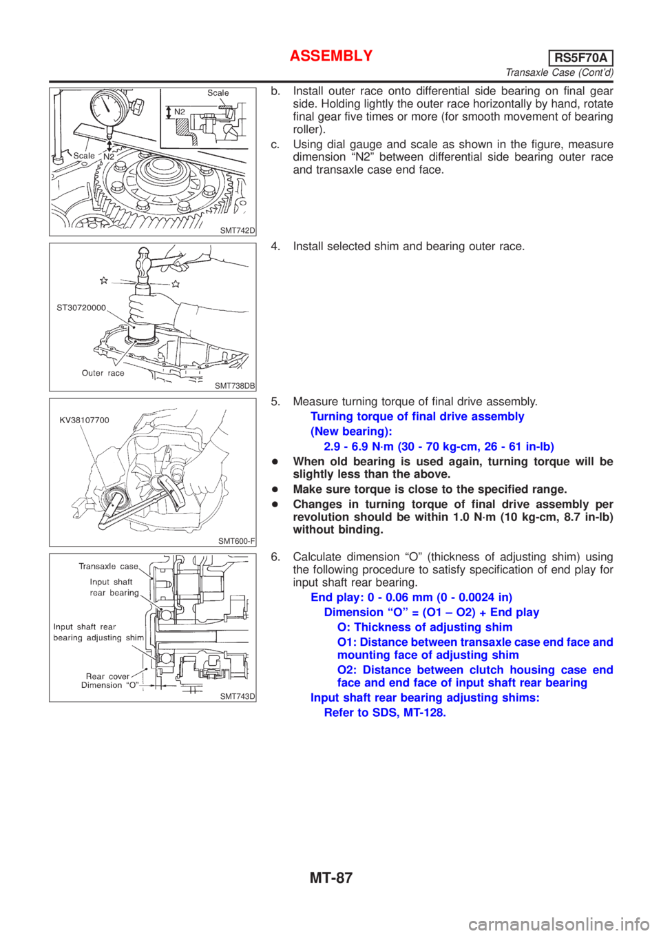
b. Install outer race onto differential side bearing on final gear
side. Holding lightly the outer race horizontally by hand, rotate
final gear five times or more (for smooth movement of bearing
roller).
c. Using dial gauge and scale as shown in the figure, measure
dimension ªN2º between differential side bearing outer race
and transaxle case end face.
SMT738DB
4. Install selected shim and bearing outer race.
SMT600-F
5. Measure turning torque of final drive assembly.
Turning torque of final drive assembly
(New bearing):
2.9 - 6.9 N´m (30 - 70 kg-cm, 26 - 61 in-lb)
+When old bearing is used again, turning torque will be
slightly less than the above.
+Make sure torque is close to the specified range.
+Changes in turning torque of final drive assembly per
revolution should be within 1.0 N´m (10 kg-cm, 8.7 in-lb)
without binding.
SMT743D
6. Calculate dimension ªOº (thickness of adjusting shim) using
the following procedure to satisfy specification of end play for
input shaft rear bearing.
End play: 0 - 0.06 mm (0 - 0.0024 in)
Dimension ªOº = (O1 ± O2) + End play
O: Thickness of adjusting shim
O1: Distance between transaxle case end face and
mounting face of adjusting shim
O2: Distance between clutch housing case end
face and end face of input shaft rear bearing
Input shaft rear bearing adjusting shims:
Refer to SDS, MT-128.
ASSEMBLYRS5F70A
Transaxle Case (Cont'd)
MT-87
Page 1138 of 2493
SMT744D
a. Using block gauge, scale, and dial gauge, measure dimension
ªO1º between transaxle case end face and mounting face of
adjusting shim.
SMT745D
b. Using gauge block, scale, and dial gauge as shown in the
figure, measure dimension ªO2º between clutch housing case
end face and end face of input shaft rear bearing.
7. Install selected input shaft rear bearing adjusting shim onto
input shaft.
SMT650D
8. Install oil gutter into transaxle case.
SMT755D
9. Install two magnets.
SMT802D
10. Clean mating surfaces of clutch housing and transaxle case.
Check for cracks and damage. Then, apply Three Bond
TB1215, Loctite Part No. 51813 or equivalent.
ASSEMBLYRS5F70A
Transaxle Case (Cont'd)
MT-88
Page 1139 of 2493

SMT649D
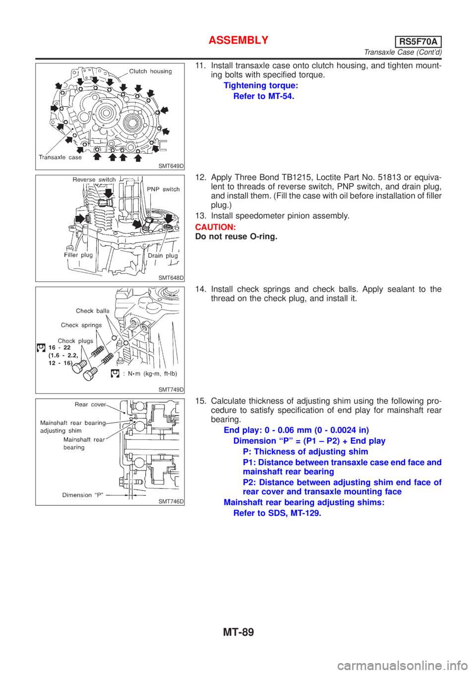
11. Install transaxle case onto clutch housing, and tighten mount-
ing bolts with specified torque.
Tightening torque:
Refer to MT-54.
SMT648D
12. Apply Three Bond TB1215, Loctite Part No. 51813 or equiva-
lent to threads of reverse switch, PNP switch, and drain plug,
and install them. (Fill the case with oil before installation of filler
plug.)
13. Install speedometer pinion assembly.
CAUTION:
Do not reuse O-ring.
SMT749D
14. Install check springs and check balls. Apply sealant to the
thread on the check plug, and install it.
SMT746D
15. Calculate thickness of adjusting shim using the following pro-
cedure to satisfy specification of end play for mainshaft rear
bearing.
End play: 0 - 0.06 mm (0 - 0.0024 in)
Dimension ªPº = (P1 ± P2) + End play
P: Thickness of adjusting shim
P1: Distance between transaxle case end face and
mainshaft rear bearing
P2: Distance between adjusting shim end face of
rear cover and transaxle mounting face
Mainshaft rear bearing adjusting shims:
Refer to SDS, MT-129.
ASSEMBLYRS5F70A
Transaxle Case (Cont'd)
MT-89
Page 1142 of 2493
NJMT0009
Case ComponentsNJMT0009S02
SMT943D
1. Speedometer pinion
2. Differential oil seal
3. Drain plug
4. Boot
5. Striking rod oil seal
6. Magnet
7. Clutch housing8. Input shaft oil seal
9. Oil channel (Mainshaft)
10. Oil pocket
11. Oil gutter
12. Oil channel (Input shaft)
13. Transmission case14. Filler plug
15. O-ring
16. Movable plate assembly
17. PNP switch
18. Breather hose
19. Breather pipe
OVERHAULRS5F50A
Case Components
MT-92
Page 1146 of 2493
SMT662C
7. Remove reverse arm shaft while rotating it.
SMT663C
8. Remove reverse lever assembly and check ball.
+Be careful not to lose check ball.
SMT018B
9. Remove 5th & reverse check plug, spring and ball.
+Be careful not to lose check ball.
SMT664C
10. Remove stopper rings and retaining pins from 5th and 3rd &
4th fork rods.
When removing stopper rings. Use snap ring remover and
installer.
11. Remove 5th and 3rd & 4th fork rods. Then remove forks and
brackets.
SMT105C
12. Remove both input and mainshafts with 1st & 2nd fork and fork
rod as a set.
13. Remove final drive assembly.
+Always withdraw mainshaft straight out. Failure to do so
can damage resin oil channel on clutch housing side.
DISASSEMBLYRS5F50A
MT-96
Page 1161 of 2493

NJMT0022
Input Shaft End Play and Differential Side
Bearing Preload
NJMT0022S01If any of the following parts are replaced, adjust input shaft end
play.
+Input shaft
+Input shaft bearing
+Clutch housing
+Transmission case
If any of the following parts are replaced, adjust differential side
bearing preload.
+Differential case
+Differential side bearing
+Clutch housing
+Transmission case
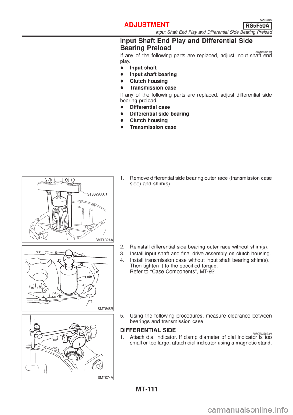
SMT132AA
1. Remove differential side bearing outer race (transmission case
side) and shim(s).
SMT845B
2. Reinstall differential side bearing outer race without shim(s).
3. Install input shaft and final drive assembly on clutch housing.
4. Install transmission case without input shaft bearing shim(s).
Then tighten it to the specified torque.
Refer to ªCase Componentsº, MT-92.
SMT074A
5. Using the following procedures, measure clearance between
bearings and transmission case.
DIFFERENTIAL SIDENJMT0022S01011. Attach dial indicator. If clamp diameter of dial indicator is too
small or too large, attach dial indicator using a magnetic stand.
ADJUSTMENTRS5F50A
Input Shaft End Play and Differential Side Bearing Preload
MT-111
Page 1162 of 2493

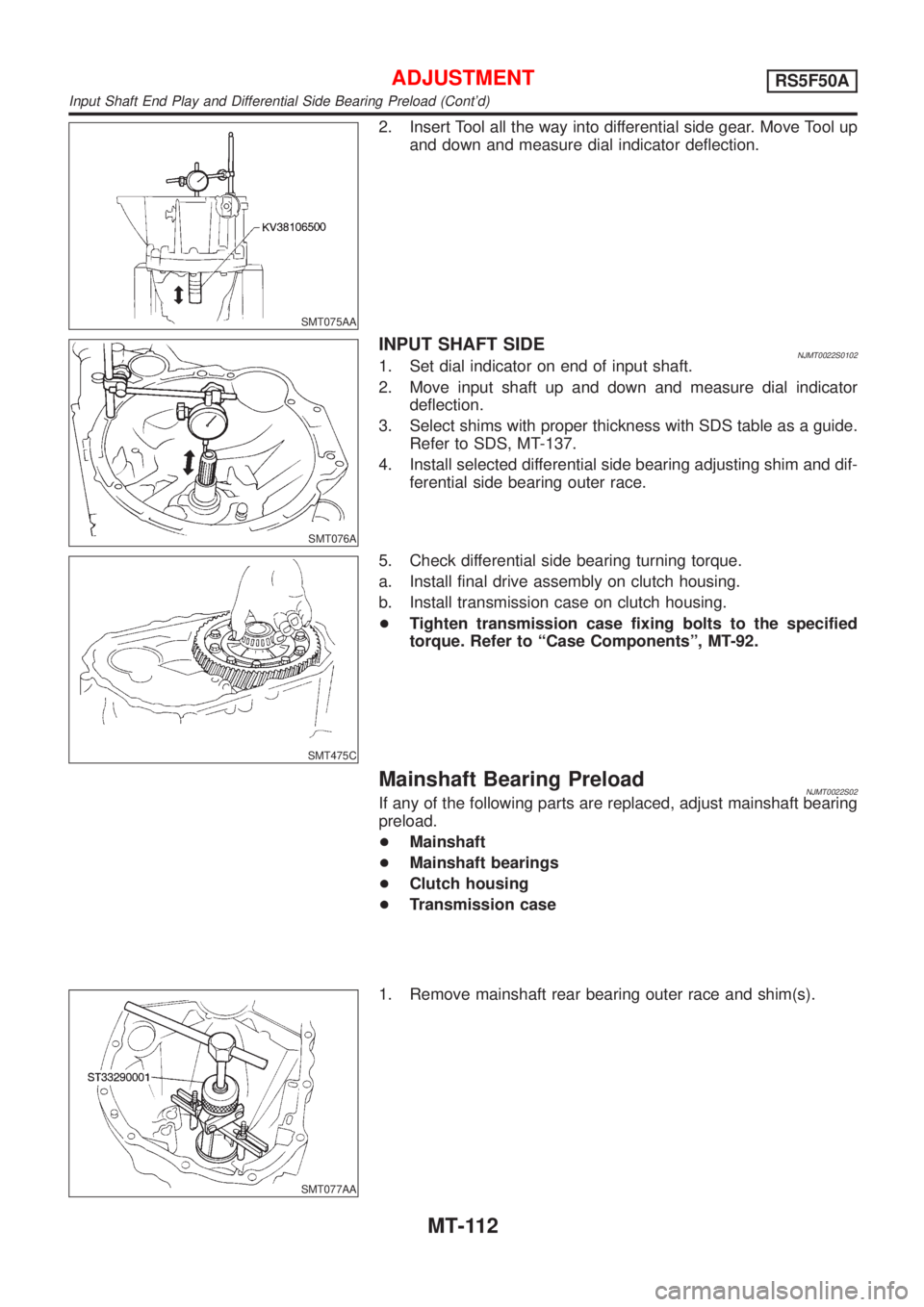
SMT075AA
2. Insert Tool all the way into differential side gear. Move Tool up
and down and measure dial indicator deflection.
SMT076A
INPUT SHAFT SIDENJMT0022S01021. Set dial indicator on end of input shaft.
2. Move input shaft up and down and measure dial indicator
deflection.
3. Select shims with proper thickness with SDS table as a guide.
Refer to SDS, MT-137.
4. Install selected differential side bearing adjusting shim and dif-
ferential side bearing outer race.
SMT475C
5. Check differential side bearing turning torque.
a. Install final drive assembly on clutch housing.
b. Install transmission case on clutch housing.
+Tighten transmission case fixing bolts to the specified
torque. Refer to ªCase Componentsº, MT-92.
Mainshaft Bearing PreloadNJMT0022S02If any of the following parts are replaced, adjust mainshaft bearing
preload.
+Mainshaft
+Mainshaft bearings
+Clutch housing
+Transmission case
SMT077AA
1. Remove mainshaft rear bearing outer race and shim(s).
ADJUSTMENTRS5F50A
Input Shaft End Play and Differential Side Bearing Preload (Cont'd)
MT-112