Page 2257 of 2493
5 CHECK CONTROL UNIT GROUND CIRCUIT
Check continuity between time control unit terminal 16 and ground.
SEL448X
Ye s©Replace time control unit.
No©Repair harness or connectors.
REAR WINDOW DEFOGGER
Trouble Diagnoses (Cont'd)
EL-145
Page 2258 of 2493
SEL970W
Electrical Components Inspection=NJEL0076REAR WINDOW DEFOGGER RELAYNJEL0076S01Check continuity between terminals 3 and 5, 6 and 7.
Condition Continuity
12V direct current supply between ter-
minals 1 and 2Ye s
No current supply No
NEL797
REAR WINDOW DEFOGGER SWITCHNJEL0076S02Check continuity between terminals when rear window defogger
switch is pushed and released.
Terminals Condition Continuity
3-5Rear window defogger
switch is pushed.Ye s
Rear window defogger
switch is released.No
REAR WINDOW DEFOGGER
Electrical Components Inspection
EL-146
Page 2259 of 2493
SEL263
Filament Check=NJEL00771. Attach probe circuit tester (in volt range) to middle portion of
each filament.
SEL122R
+When measuring voltage, wrap tin foil around the top of
the negative probe. Then press the foil against the wire
with your finger.
SEL265
2. If a filament is burned out, circuit tester registers 0 or 12 volts.
SEL266
3. To locate burned out point, move probe to left and right along
filament. Test needle will swing abruptly when probe passes
the point.
REAR WINDOW DEFOGGER
Filament Check
EL-147
Page 2260 of 2493

Filament RepairNJEL0078REPAIR EQUIPMENTNJEL0078S011) Conductive silver composition (Dupont No. 4817 or equivalent)
2) Ruler 30 cm (11.8 in) long
3) Drawing pen
4) Heat gun
5) Alcohol
6) Cloth
BE540
REPAIRING PROCEDURENJEL0078S021. Wipe broken heat wire and its surrounding area clean with a
cloth dampened in alcohol.
2. Apply a small amount of conductive silver composition to tip of
drawing pen.
Shake silver composition container before use.
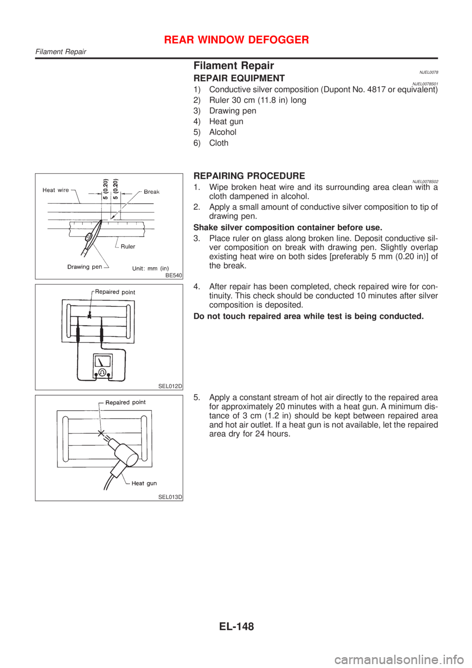
3. Place ruler on glass along broken line. Deposit conductive sil-
ver composition on break with drawing pen. Slightly overlap
existing heat wire on both sides [preferably 5 mm (0.20 in)] of
the break.
SEL012D
4. After repair has been completed, check repaired wire for con-
tinuity. This check should be conducted 10 minutes after silver
composition is deposited.
Do not touch repaired area while test is being conducted.
SEL013D
5. Apply a constant stream of hot air directly to the repaired area
for approximately 20 minutes with a heat gun. A minimum dis-
tance of 3 cm (1.2 in) should be kept between repaired area
and hot air outlet. If a heat gun is not available, let the repaired
area dry for 24 hours.
REAR WINDOW DEFOGGER
Filament Repair
EL-148
Page 2272 of 2493

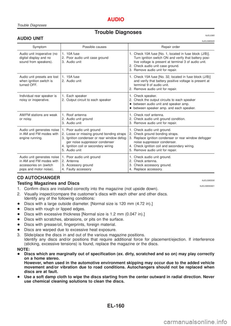
Trouble DiagnosesNJEL0385AUDIO UNITNJEL0385S05
Symptom Possible causes Repair order
Audio unit inoperative (no
digital display and no
sound from speakers).1. 10A fuse
2. Poor audio unit case ground
3. Audio unit1. Check 10A fuse [No. 1, located in fuse block (J/B)].
Turn ignition switch ON and verify that battery posi-
tive voltage is present at terminal 3 of audio unit.
2. Check audio unit case ground.
3. Remove audio unit for repair.
Audio unit presets are lost
when ignition switch is
turned OFF.1. 15A fuse
2. Audio unit1. Check 15A fuse [No. 32, located in fuse block (J/B)]
and verify that battery positive voltage is present at
terminal 9 of audio unit.
2. Remove audio unit for repair.
Individual rear speaker is
noisy or inoperative.1. Each speaker
2. Output circuit to each speaker1. Check speaker.
2. Check the output circuits to each speaker
+between audio unit and speaker amp.
+between speaker amp. and each speaker.
AM/FM stations are weak
or noisy.1. Roof antenna
2. Audio unit ground
3. Audio unit1. Check roof antenna.
2. Check audio unit ground condition.
3. Remove audio unit for repair.
Audio unit generates noise
in AM and FM modes with
engine running.1. Poor audio unit ground
2. Loose or missing ground bonding straps
3. Ignition condenser or rear window defog-
ger noise suppressor condenser
4. Ignition coil or secondary wiring
5. Audio unit1. Check audio unit ground.
2. Check ground bonding straps.
3. Replace ignition condenser or rear window defogger
noise suppressor condenser.
4. Check ignition coil and secondary wiring.
5. Remove audio unit for repair.
Audio unit generates noise
in AM and FM modes with
accessories on (switch
pops and motor noise).1. Poor audio unit ground
2. Antenna
3. Accessory ground
4. Faulty accessory1. Check audio unit ground.
2. Check antenna.
3. Check accessory ground.
4. Replace accessory.
CD AUTOCHANGERNJEL0385S06Testing Magazines and DiscsNJEL0385S06011. Confirm discs are installed correctly into the magazine (not upside down).
2. Visually inspect/compare the customer's discs with each other and other discs.
Identify any of the following conditions:
+Discs with a large outside diameter. [Normal size is 120 mm (4.72 in).]
+Discs with rough or lipped edges.
+Discs with excessive thickness [Normal size is 1.2 mm (0.047 in).]
+Discs with scratches, abrasions, or pits on the surface.
+Discs with grease/oil, fingerprints, foreign material.
+Discs are warped due to excessive heat exposure.
3. Slide/place the discs in and out of the various magazine positions.
Identify any discs and/or positions that require additional force for placement/ejection. If interference
(sticking, excessive tensions) is found, replace the magazine or the discs.
NOTE:
+Discs which are marginally out of specification (ex. dirty, scratched and so on) may play correctly
on a home stereo.
However, when used in the automotive environment skipping may occur due to the added vehicle
movement and/or vibration due to road conditions. Autochangers should not be replaced when
discs are at fault.
+Use a soft damp cloth to wipe the discs starting from the center outward in radial direction. Never
use chemical cleaning solutions to clean the discs.
AUDIO
Trouble Diagnoses
EL-160
Page 2281 of 2493

System Description=NJEL0498Power is supplied at all times
+from 30A fusible link (letterE, located in the fuse and fusible link box)
+to circuit breaker terminal 1
+through circuit breaker terminal 2
+to power window relay terminal 5
With ignition switch in ON or START position, power is supplied
+through 10A fuse [No. 10, located in the fuse block (J/B)]
+to power window relay terminal 1
Ground is supplied to power window relay terminal 2
+through body grounds M28 and M67.
The power window relay is energized and power is supplied
+through power window relay terminal 3
+to power window main switch terminal 1,
+to front power window sub-switch terminal 5,
+to rear power window sub-switch LH and RH terminals 5 (models with rear power window).
MANUAL OPERATIONNJEL0498S01Front Door (Driver Side)NJEL0498S0101Ground is supplied
+to power window main switch terminal 3
+through body grounds M28 and M67.
WINDOW UP
When the driver's window switch in the power window main switch is pressed in the up position, power is
supplied
+through power window main switch terminal 9
+to driver side power window regulator terminal 1.
Ground is supplied
+through power window main switch terminal 2
+to driver side power window regulator terminal 8.
Then, the motor raises the window until the switch is released.
WINDOW DOWN
When the driver's window switch in the power window main switch is pressed in the down position, power is
supplied
+through power window main switch terminal 8
+to driver side power window regulator terminal 2.
Ground is supplied
+to driver side power window regulator terminal 1
+through power window main switch terminal 9.
Then, the motor lowers the window until the switch is released.
Front Door (Passenger Side)NJEL0498S0102Ground is supplied
+to power window main switch terminal 3
+through body grounds M28 and M67.
NOTE:
Numbers in parentheses are terminal numbers, when power window switch is pressed in the UP and DOWN
positions respectively.
POWER WINDOW MAIN SWITCH OPERATION
Power is supplied
+through power window main switch (5, 6)
+to front power window sub-switch (3, 4).
POWER WINDOW
System Description
EL-169
Page 2282 of 2493

The subsequent operation is the same as the front power window sub-switch operation.
FRONT POWER WINDOW SUB-SWITCH OPERATION
Power is supplied
+through front power window sub-switch (1, 2)
+to front passenger side power window regulator (1, 2).
Ground is supplied
+to front passenger side power window regulator (2, 1)
+through front power window sub-switch (2, 1)
+to front power window sub-switch (4, 3)
+through power window main switch (6, 5).
Then, the motor raises or lowers the window until the switch is released.
Rear DoorNJEL0498S0103Rear door windows will raise and lower in the same manner as passenger's door window.
POWER WINDOW LOCKNJEL0498S02The power window lock is designed to lock operation of all windows except for driver's door window.
When the lock switch is pressed to lock position, ground of the sub-switches in the power window main switch
is disconnected. This prevents the power window motors from operating.
AUTO OPERATIONNJEL0498S03The power window AUTO feature enables the driver to open the driver's window without holding the window
switch in the down position.
The AUTO feature operates on the driver's window.
POWER WINDOW
System Description (Cont'd)
EL-170
Page 2283 of 2493
SchematicNJEL0499
MEL916L
POWER WINDOW
Schematic
EL-171