Page 2148 of 2493
ROOM LAMP AND REAR WINDOW DEFOGGER HARNESSNJEL0008S08
YEL615C
GROUND
Ground Distribution (Cont'd)
EL-36
Page 2250 of 2493

System Description=NJEL0463The rear window defogger system is controlled by the time control unit. The rear window defogger operates
only for approximately 15 minutes.
Power is supplied at all times
+through 20A fuse [No. 7, located in the fuse block (J/B)]
+to rear window defogger relay terminal 5 (B7 relay models) or 3 (B6 relay models)
+through 10A fuse [No. 13, located in the fuse block (J/B)]
+to rear window defogger relay terminal 6 (B6 relay models).
+through 15A fuse [No. 5, located in the fuse block (J/B)]
+to time control unit terminal 9.
With the ignition switch in the ON or START position, power is supplied
+through 10A fuse [No. 10, located in the fuse block (J/B)]
+to the rear window defogger relay terminal 1 and
+to time control unit terminal 1.
Ground is supplied to terminal 5 of the rear window defogger switch through body grounds M28 and M67.
When the rear defogger switch is turned ON, ground is supplied
+through terminal 3 of the rear defogger switch
+to time control unit terminal 3.
Terminal 13 of time control unit then supplies ground to the rear window defogger relay terminal 2.
With power and ground supplied, the rear window defogger relay is energized.
Power is supplied
+through terminals 5 and 7 of the rear window defogger relay (B6 relay models) or
+through terminal 3 of the rear window defogger relay (B7 relay models)
+to the rear window defogger and door mirror defogger.
The rear window defogger has an independent ground.
With power and ground supplied, the rear window defogger filaments heat and defog the rear window.
When the system is activated, the rear window defogger indicator illuminates in the rear window defogger
switch.
REAR WINDOW DEFOGGER
System Description
EL-138
Page 2251 of 2493
SchematicNJEL0533
YEL667C
REAR WINDOW DEFOGGER
Schematic
EL-139
Page 2252 of 2493
Wiring Diagram Ð DEF Ð=NJEL0464
YEL668C
REAR WINDOW DEFOGGER
Wiring Diagram Ð DEF Ð
EL-140
Page 2253 of 2493
YEL669C
REAR WINDOW DEFOGGER
Wiring Diagram Ð DEF Ð (Cont'd)
EL-141
Page 2254 of 2493
YEL670C
REAR WINDOW DEFOGGER
Wiring Diagram Ð DEF Ð (Cont'd)
EL-142
Page 2255 of 2493

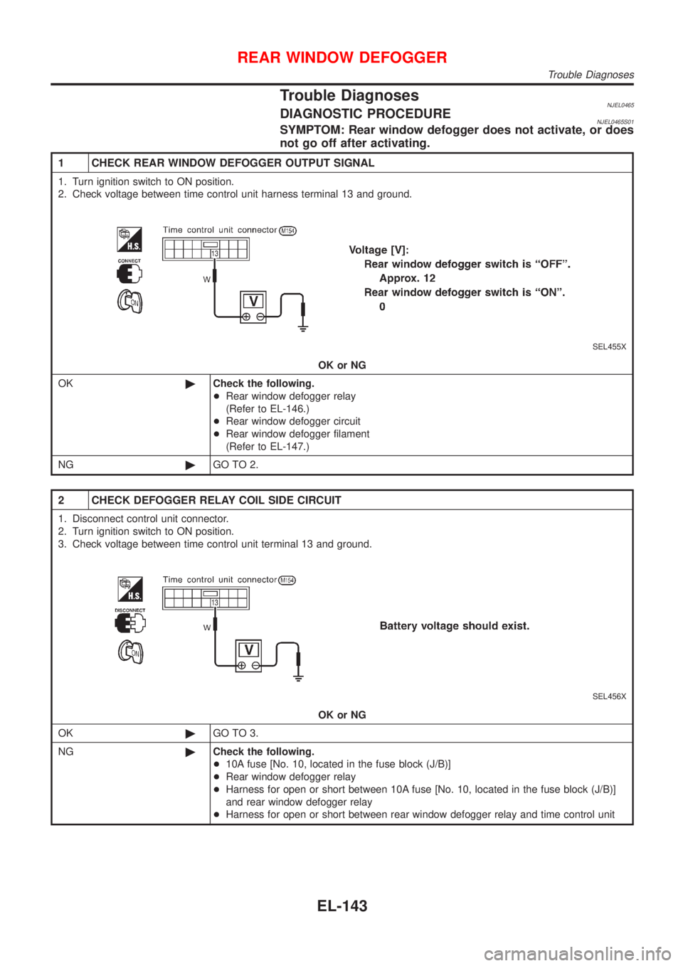
Trouble DiagnosesNJEL0465DIAGNOSTIC PROCEDURENJEL0465S01SYMPTOM: Rear window defogger does not activate, or does
not go off after activating.
1 CHECK REAR WINDOW DEFOGGER OUTPUT SIGNAL
1. Turn ignition switch to ON position.
2. Check voltage between time control unit harness terminal 13 and ground.
SEL455X
OK or NG
OK©Check the following.
+Rear window defogger relay
(Refer to EL-146.)
+Rear window defogger circuit
+Rear window defogger filament
(Refer to EL-147.)
NG©GO TO 2.
2 CHECK DEFOGGER RELAY COIL SIDE CIRCUIT
1. Disconnect control unit connector.
2. Turn ignition switch to ON position.
3. Check voltage between time control unit terminal 13 and ground.
SEL456X
OK or NG
OK©GO TO 3.
NG©Check the following.
+10A fuse [No. 10, located in the fuse block (J/B)]
+Rear window defogger relay
+Harness for open or short between 10A fuse [No. 10, located in the fuse block (J/B)]
and rear window defogger relay
+Harness for open or short between rear window defogger relay and time control unit
REAR WINDOW DEFOGGER
Trouble Diagnoses
EL-143
Page 2256 of 2493
3 CHECK REAR WINDOW DEFOGGER SWITCH INPUT SIGNAL
Check continuity between time control unit terminal 3 and ground.
SEL457X
OK or NG
OK©GO TO 4.
NG©Check the following.
+Rear window defogger switch
(Refer to EL-146.)
+Harness for open or short between time control unit and rear window defogger switch
+Rear window defogger switch ground circuit
4 CHECK POWER SUPPLY AND IGNITION INPUT SIGNAL
Check voltage between time control unit terminals 1 or 9 and ground.
SEL447X
OK or NG
OK©GO TO 5.
NG©Check the following.
+10A fuse or 15A fuse [No. 10 or No. 5, located in the fuse block (J/B)]
+Harness for open or short between time control unit and fuse
REAR WINDOW DEFOGGER
Trouble Diagnoses (Cont'd)
EL-144