2001 NISSAN ALMERA N16 page 71
[x] Cancel search: page 71Page 368 of 2493

SEF543X
NATS (Nissan Anti-theft System)NJEC0591+If the security indicator lights up with the ignition switch
in the ªONº position or ªNATS MALFUNCTIONº is dis-
played on ªSELF-DIAG RESULTSº screen, perform self-
diagnostic results mode with CONSULT-II using NATS pro-
gram card. Refer to NATS (Nissan Anti-Theft System) in EL
section.
+Confirm no self-diagnostic results of NATS is displayed
before touching ªERASEº in ªSELF-DIAG RESULTSº
mode with CONSULT-II.
+When replacing ECM, initialization of NATS system and
registration of all NATS ignition key IDs must be carried
out with CONSULT-II using NATS program card.
Therefore, be sure to receive all keys from vehicle owner.
Regarding the procedure of NATS initialization and NATS
ignition key ID registration, refer to CONSULT-II operation
manual, NATS.
Malfunction Indicator (MI)
DESCRIPTIONNJEC0032
SAT652J
The MI is located on the instrument panel.
1. The MI will light up when the ignition switch is turned ON without the engine running. This is a bulb check.
+If the MI does not light up, refer to EL-107, ªWARNING LAMPSº or see EC-488.
2. When the engine is started, the MI should go off.
If the MI remains on, the on board diagnostic system has detected an engine system malfunction.
On Board Diagnostic System FunctionNJEC0032S01The on board diagnostic system has the following four functions.
Diagnostic Test Mode I
1. BULB CHECK:
This function checks the MI bulb for damage (blown, open circuit, etc.).
If the MI does not come on, check MI circuit and ECM test mode selector. (See the following page.)
2. MALFUNCTION WARNING:
MI Condition
ON When the malfunction is detected or the ECM's CPU is malfunctioning.
OFF No malfunction.
Diagnostic Test Mode II (If so equipped)
ON BOARD DIAGNOSTIC SYSTEM DESCRIPTIONQG
NATS (Nissan Anti-theft System)
EC-72
Page 386 of 2493
DTC Work Support ModeNJEC0034S0802
TEST MODE TEST ITEM CONDITION REFERENCE PAGE
HEATED OXYGEN SEN-
SOR 1 (FRONT)HO2S1 (B1) P0130
Refer to corresponding
trouble diagnosis for
DTC.EC-176
HO2S1 (B1) P0131 EC-183
HO2S1 (B1) P0132 EC-189
HO2S1 (B1) P0133 EC-195
HEATED OXYGEN SEN-
SOR 2 (REAR)HO2S2 (B1) P0137 EC-214
HO2S2 (B1) P0138 EC-222
HO2S2 (B1) P0139 EC-229
EGR SYSTEM
(If so equipped)EGR SYSTEM P0400 EC-285
EGR SYSTEM P1402 EC-353
SEF705Y
SEF707X
REAL TIME DIAGNOSIS IN DATA MONITOR MODE
(RECORDING VEHICLE DATA)
NJEC0034S10CONSULT-II has two kinds of triggers and they can be selected by
touching ªSETTINGº in ªDATA MONITORº mode.
1) ªAUTO TRIGº (Automatic trigger):
+The malfunction will be identified on the CONSULT-II screen in
real time.
In other words, DTC/1st trip DTC and malfunction item will be
displayed if the malfunction is detected by ECM.
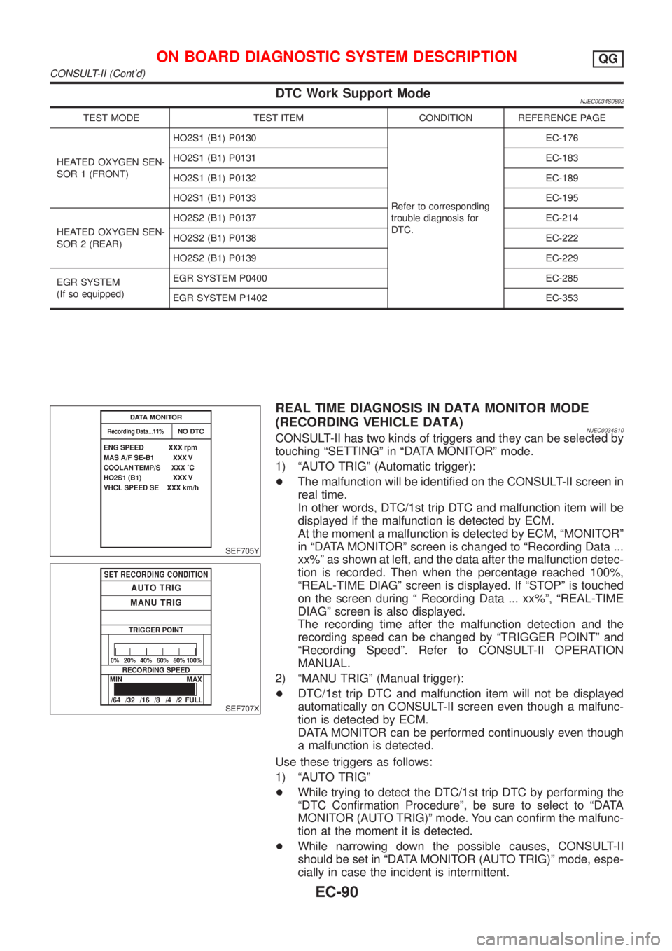
At the moment a malfunction is detected by ECM, ªMONITORº
in ªDATA MONITORº screen is changed to ªRecording Data ...
xx%º as shown at left, and the data after the malfunction detec-
tion is recorded. Then when the percentage reached 100%,
ªREAL-TIME DIAGº screen is displayed. If ªSTOPº is touched
on the screen during ª Recording Data ... xx%º, ªREAL-TIME
DIAGº screen is also displayed.
The recording time after the malfunction detection and the
recording speed can be changed by ªTRIGGER POINTº and
ªRecording Speedº. Refer to CONSULT-II OPERATION
MANUAL.
2) ªMANU TRIGº (Manual trigger):
+DTC/1st trip DTC and malfunction item will not be displayed
automatically on CONSULT-II screen even though a malfunc-
tion is detected by ECM.
DATA MONITOR can be performed continuously even though
a malfunction is detected.
Use these triggers as follows:
1) ªAUTO TRIGº
+While trying to detect the DTC/1st trip DTC by performing the
ªDTC Confirmation Procedureº, be sure to select to ªDATA
MONITOR (AUTO TRIG)º mode. You can confirm the malfunc-
tion at the moment it is detected.
+While narrowing down the possible causes, CONSULT-II
should be set in ªDATA MONITOR (AUTO TRIG)º mode, espe-
cially in case the incident is intermittent.
ON BOARD DIAGNOSTIC SYSTEM DESCRIPTIONQG
CONSULT-II (Cont'd)
EC-90
Page 388 of 2493
SEF139P
Generic Scan Tool (GST)=NJEC0035DESCRIPTIONNJEC0035S01Generic Scan Tool (OBDII scan tool) complying with ISO15031-4
has 9 different functions explained on the next page.
ISO9141 is used as the protocol.
The name ªGSTº or ªGeneric Scan Toolº is used in this service
manual.
SEF094Y
GST INSPECTION PROCEDURENJEC0035S021. Turn ignition switch OFF.
2. Connect ªGSTº to data link connector. (Data link connector is
located under lower dash panel near the fuse box cover.)
SEF398S
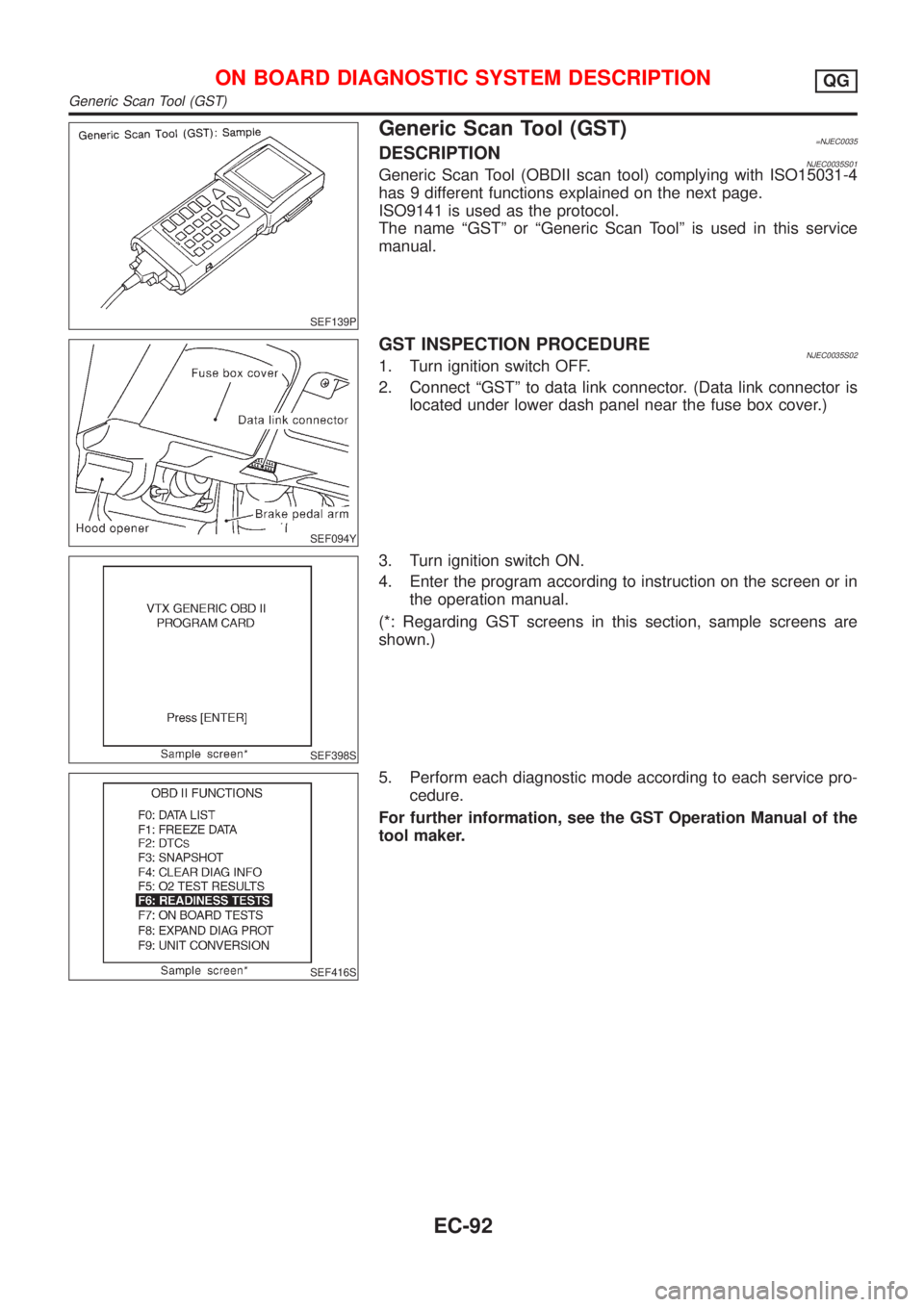
3. Turn ignition switch ON.
4. Enter the program according to instruction on the screen or in
the operation manual.
(*: Regarding GST screens in this section, sample screens are
shown.)
SEF416S
5. Perform each diagnostic mode according to each service pro-
cedure.
For further information, see the GST Operation Manual of the
tool maker.
ON BOARD DIAGNOSTIC SYSTEM DESCRIPTIONQG
Generic Scan Tool (GST)
EC-92
Page 390 of 2493
MEF036D
SEF233G
SEF234G
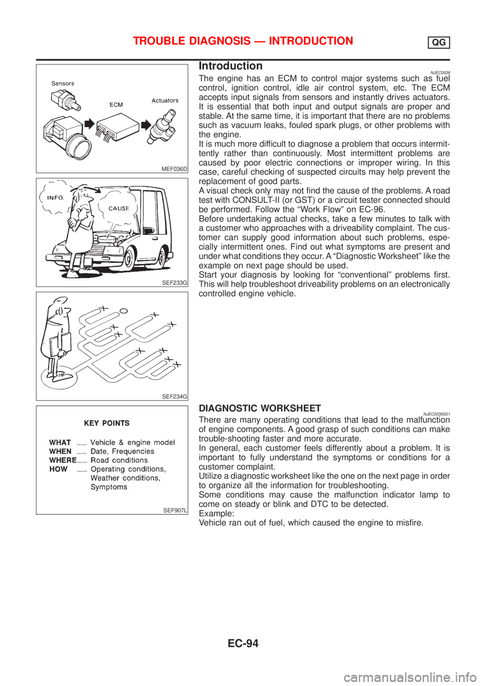
IntroductionNJEC0036The engine has an ECM to control major systems such as fuel
control, ignition control, idle air control system, etc. The ECM
accepts input signals from sensors and instantly drives actuators.
It is essential that both input and output signals are proper and
stable. At the same time, it is important that there are no problems
such as vacuum leaks, fouled spark plugs, or other problems with
the engine.
It is much more difficult to diagnose a problem that occurs intermit-
tently rather than continuously. Most intermittent problems are
caused by poor electric connections or improper wiring. In this
case, careful checking of suspected circuits may help prevent the
replacement of good parts.
A visual check only may not find the cause of the problems. A road
test with CONSULT-II (or GST) or a circuit tester connected should
be performed. Follow the ªWork Flowº on EC-96.
Before undertaking actual checks, take a few minutes to talk with
a customer who approaches with a driveability complaint. The cus-
tomer can supply good information about such problems, espe-
cially intermittent ones. Find out what symptoms are present and
under what conditions they occur. A ªDiagnostic Worksheetº like the
example on next page should be used.
Start your diagnosis by looking for ªconventionalº problems first.
This will help troubleshoot driveability problems on an electronically
controlled engine vehicle.
SEF907L
DIAGNOSTIC WORKSHEETNJEC0036S01There are many operating conditions that lead to the malfunction
of engine components. A good grasp of such conditions can make
trouble-shooting faster and more accurate.
In general, each customer feels differently about a problem. It is
important to fully understand the symptoms or conditions for a
customer complaint.
Utilize a diagnostic worksheet like the one on the next page in order
to organize all the information for troubleshooting.
Some conditions may cause the malfunction indicator lamp to
come on steady or blink and DTC to be detected.
Example:
Vehicle ran out of fuel, which caused the engine to misfire.
TROUBLE DIAGNOSIS Ð INTRODUCTIONQG
EC-94
Page 420 of 2493

Symptom Matrix ChartNJEC0041SYSTEM Ð ENGINE CONTROL SYSTEMNJEC0041S01
SYMPTOM
Reference
page
HARD/NO START/RESTART (EXCP. HA)
ENGINE STALL
HESITATION/SURGING/FLAT SPOT
SPARK KNOCK/DETONATION
LACK OF POWER/POOR ACCELERATION
HIGH IDLE/LOW IDLE
ROUGH IDLE/HUNTING
IDLING VIBRATION
SLOW/NO RETURN TO IDLE
OVERHEATS/WATER TEMPERATURE HIGH
EXCESSIVE FUEL CONSUMPTION
EXCESSIVE OIL CONSUMPTION
BATTERY DEAD (UNDER CHARGE)
Warranty symptom code AA AB AC AD AE AF AG AH AJ AK AL AM HA
Fuel Fuel pump circuit11232 22 3 2EC-464
Fuel pressure regulator sys-
tem334444444 4EC-39
Injector circuit11232 22 2EC-447
Evaporative emission sys-
tem334444444 4EC-33
Air Positive crankcase ventila-
tion system334444444 41EC-37
Incorrect idle speed adjust-
ment3 3 1 1 1 1 1 EC-41
IACV-AAC valve circuit112332222 2 2EC-313
Ignition Incorrect ignition timing
adjustment33111 11 1EC-41
Ignition circuit11222 22 2EC-451
EGR EGR volume control valve
circuit2233 3EC-293
EGR system212333223 3EC-285,
293, 353
Main power supply and ground circuit22333 33 23 2EC-145
Air conditioner circuit223333333 3 2HAsection
1 - 6: The numbers refer to the order of inspection.
(continued on next page)
TROUBLE DIAGNOSIS Ð GENERAL DESCRIPTIONQG
Symptom Matrix Chart
EC-124
Page 421 of 2493

SYMPTOM
Reference
page
HARD/NO START/RESTART (EXCP. HA)
ENGINE STALL
HESITATION/SURGING/FLAT SPOT
SPARK KNOCK/DETONATION
LACK OF POWER/POOR ACCELERATION
HIGH IDLE/LOW IDLE
ROUGH IDLE/HUNTING
IDLING VIBRATION
SLOW/NO RETURN TO IDLE
OVERHEATS/WATER TEMPERATURE HIGH
EXCESSIVE FUEL CONSUMPTION
EXCESSIVE OIL CONSUMPTION
BATTERY DEAD (UNDER CHARGE)
Warranty symptom code AA AB AC AD AE AF AG AH AJ AK AL AM HA
Crankshaft position sensor (POS)
circuit22EC-272
Camshaft position sensor
(PHASE) circuit3 2 3 EC-278
Mass air flow sensor circuit11222 22 2EC-152
Heated oxygen sensor 1 (front)
circuit1232 22 2EC-176,
183
Engine coolant temperature sen-
sor circuit112323223 2EC-163,
165
Throttle position sensor circuit 1 222222 2EC-168
Incorrect throttle position sensor
adjustment31 11111 1EC-98
Vehicle speed sensor circuit 2 3 3 3 EC-309
Knock sensor circuit 2 3 EC-268
ECM 22333333333EC-327,
123
Start signal circuit 2EC-461
PNP switch circuit 3 3 3 3 3 EC-364
Power steering oil pressure switch
circuit2 3 3 EC-471
Electrical load signal circuit 3 3 EC-480
1 - 6: The numbers refer to the order of inspection.
(continued on next page)
TROUBLE DIAGNOSIS Ð GENERAL DESCRIPTIONQG
Symptom Matrix Chart (Cont'd)
EC-125
Page 422 of 2493
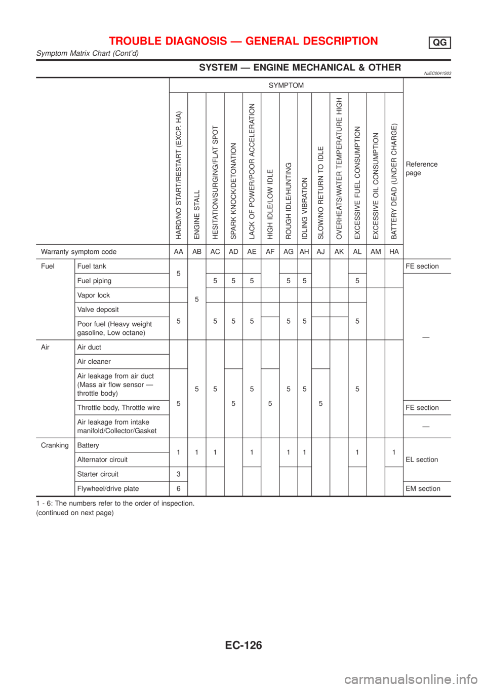
SYSTEM Ð ENGINE MECHANICAL & OTHERNJEC0041S03
SYMPTOM
Reference
page
HARD/NO START/RESTART (EXCP. HA)
ENGINE STALL
HESITATION/SURGING/FLAT SPOT
SPARK KNOCK/DETONATION
LACK OF POWER/POOR ACCELERATION
HIGH IDLE/LOW IDLE
ROUGH IDLE/HUNTING
IDLING VIBRATION
SLOW/NO RETURN TO IDLE
OVERHEATS/WATER TEMPERATURE HIGH
EXCESSIVE FUEL CONSUMPTION
EXCESSIVE OIL CONSUMPTION
BATTERY DEAD (UNDER CHARGE)
Warranty symptom code AA AB AC AD AE AF AG AH AJ AK AL AM HA
Fuel Fuel tank
5
5FE section
Fuel piping 5 5 5 5 5 5
Ð Vapor lock
Valve deposit
5 555 55 5
Poor fuel (Heavy weight
gasoline, Low octane)
Air Air duct
55555 5 Air cleaner
Air leakage from air duct
(Mass air flow sensor Ð
throttle body)
5555
Throttle body, Throttle wireFE section
Air leakage from intake
manifold/Collector/GasketÐ
Cranking Battery
111111 11
EL section Alternator circuit
Starter circuit 3
Flywheel/drive plate 6EM section
1 - 6: The numbers refer to the order of inspection.
(continued on next page)
TROUBLE DIAGNOSIS Ð GENERAL DESCRIPTIONQG
Symptom Matrix Chart (Cont'd)
EC-126
Page 423 of 2493
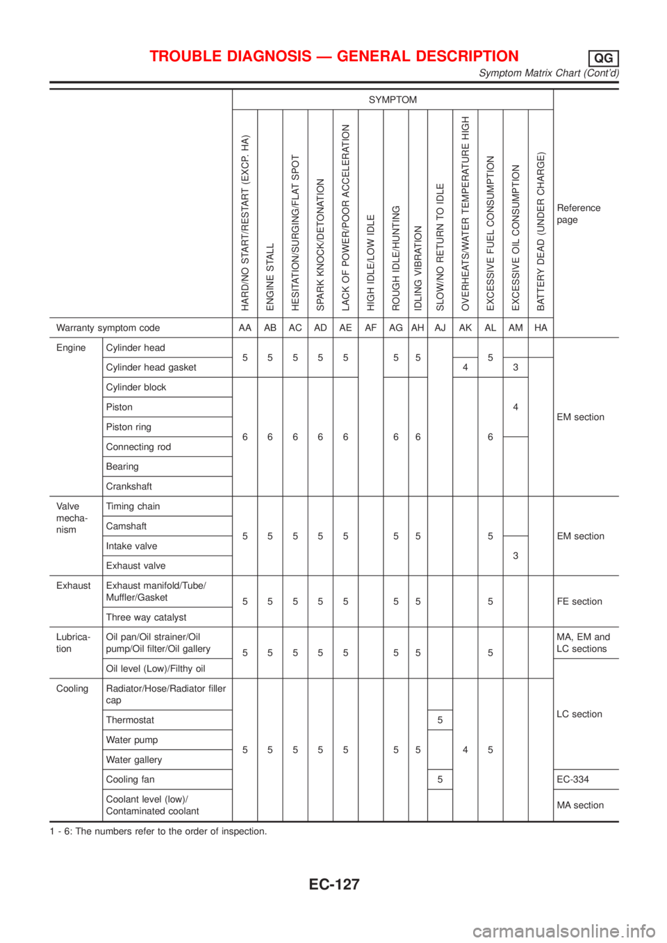
SYMPTOM
Reference
page
HARD/NO START/RESTART (EXCP. HA)
ENGINE STALL
HESITATION/SURGING/FLAT SPOT
SPARK KNOCK/DETONATION
LACK OF POWER/POOR ACCELERATION
HIGH IDLE/LOW IDLE
ROUGH IDLE/HUNTING
IDLING VIBRATION
SLOW/NO RETURN TO IDLE
OVERHEATS/WATER TEMPERATURE HIGH
EXCESSIVE FUEL CONSUMPTION
EXCESSIVE OIL CONSUMPTION
BATTERY DEAD (UNDER CHARGE)
Warranty symptom code AA AB AC AD AE AF AG AH AJ AK AL AM HA
Engine Cylinder head
55555 55 5
EM section Cylinder head gasket 4 3
Cylinder block
66666 66 64 Piston
Piston ring
Connecting rod
Bearing
Crankshaft
Valve
mecha-
nismTiming chain
55555 55 5 EMsection Camshaft
Intake valve
3
Exhaust valve
Exhaust Exhaust manifold/Tube/
Muffler/Gasket
55555 55 5 FEsection
Three way catalyst
Lubrica-
tionOil pan/Oil strainer/Oil
pump/Oil filter/Oil gallery
55555 55 5MA, EM and
LC sections
Oil level (Low)/Filthy oil
LC section Cooling Radiator/Hose/Radiator filler
cap
55555 55 45 Thermostat 5
Water pump
Water gallery
Cooling fan 5 EC-334
Coolant level (low)/
Contaminated coolantMA section
1 - 6: The numbers refer to the order of inspection.
TROUBLE DIAGNOSIS Ð GENERAL DESCRIPTIONQG
Symptom Matrix Chart (Cont'd)
EC-127