2001 NISSAN ALMERA N16 radiator cap
[x] Cancel search: radiator capPage 641 of 2493
Main 12 Causes of Overheating=NJEC0492
Engine Step Inspection item Equipment Standard Reference page
OFF 1+Blocked radiator
+Blocked condenser
+Blocked radiator grille
+Blocked bumper+Visual No blocking Ð
2+Coolant mixture+Coolant tester 50 - 50% coolant mixture See MA-20, ªRECOM-
MENDED FLUIDS AND
LUBRICANTSº.
3+Coolant level+Visual Coolant up to MAX level
in reservoir tank and
radiator filler neckSee LC-17, ªChanging
Engine Coolantº.
4+Radiator cap+Pressure tester 59 - 98 kPa
(0.59 - 0.98 bar, 0.6 - 1.0
kg/cm
2,9-14psi) (Limit)See LC-10, ªSystem
Checkº.
ON*
25+Coolant leaks+Visual No leaks See LC-10, ªSystem
Checkº.
ON*
26+Thermostat+Touch the upper and
lower radiator hosesBoth hoses should be
hotSee LC-15, ªThermostatº
and LC-16, ªRadiatorº.
ON*
17+Cooling fan+CONSULT-II Operating See ªTROUBLE DIAG-
NOSIS FOR OVER-
HEATº (EC-334).
OFF 8+Combustion gas leak+Color checker chemi-
cal tester 4 Gas ana-
lyzerNegative Ð
ON*
39+Coolant temperature
gauge+Visual Gauge less than 3/4
when drivingÐ
+Coolant overflow to
reservoir tank+Visual No overflow during driv-
ing and idlingSee LC-17, ªChanging
Engine Coolantº.
OFF*
410+Coolant return from
reservoir tank to radia-
tor+Visual Should be initial level in
reservoir tankSee LC-18, ªRefilling
Engine Coolantº.
OFF 11+Cylinder head+Straight gauge feeler
gauge0.1 mm (0.004 in) Maxi-
mum distortion (warping)See EM-36, ªInspectionº,
ªCYLINDER HEADº.
12+Cylinder block and
pistons+Visual No scuffing on cylinder
walls or pistonSee EM-54, ªInspectionº,
ªCYLINDER BLOCKº.
*1: Turn the ignition switch ON.
*2: Engine running at 3,000 rpm for 10 minutes.
*3: Drive at 90 km/h (55 MPH) for 30 minutes and then let idle for 10 minutes.
*4: After 60 minutes of cool down time.
For more information, refer to LC-23, ª OVERHEATING CAUSE ANALYSISº.
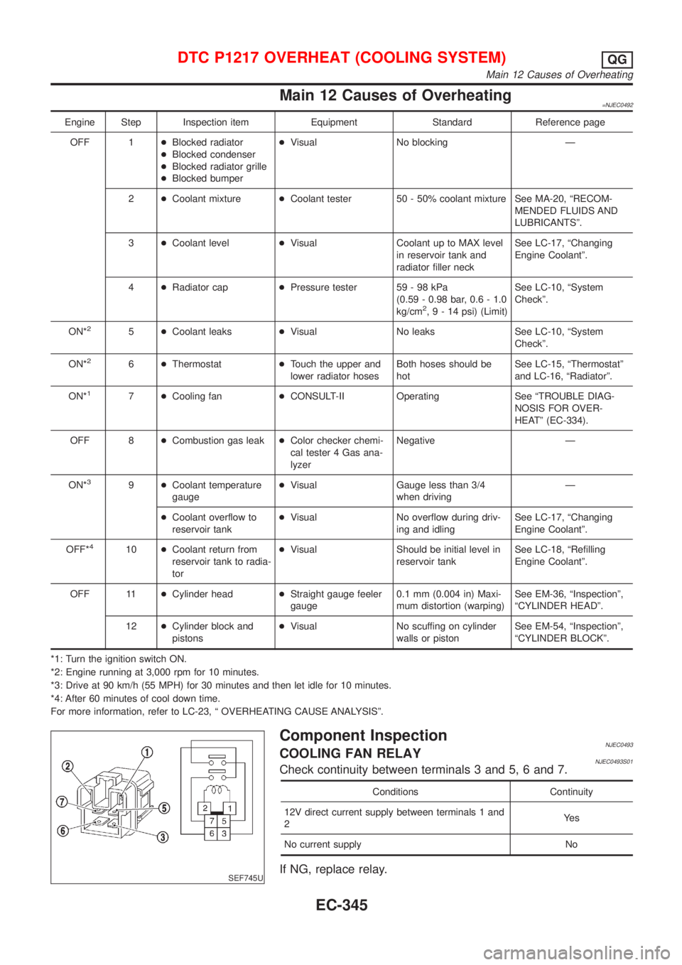
SEF745U
Component InspectionNJEC0493COOLING FAN RELAYNJEC0493S01Check continuity between terminals 3 and 5, 6 and 7.
Conditions Continuity
12V direct current supply between terminals 1 and
2Ye s
No current supply No
If NG, replace relay.
DTC P1217 OVERHEAT (COOLING SYSTEM)QG
Main 12 Causes of Overheating
EC-345
Page 915 of 2493
![NISSAN ALMERA N16 2001 Electronic Repair Manual TERMI-
NAL
NO.WIRE
COLORITEM CONDITION DATA(DC Voltage)
221 LG/B Cooling fan relay (High)[Engine is running]
+Cooling fans are not operating
+Cooling fans are operating at low speedBATTERY VOLTAGE
(11 NISSAN ALMERA N16 2001 Electronic Repair Manual TERMI-
NAL
NO.WIRE
COLORITEM CONDITION DATA(DC Voltage)
221 LG/B Cooling fan relay (High)[Engine is running]
+Cooling fans are not operating
+Cooling fans are operating at low speedBATTERY VOLTAGE
(11](/manual-img/5/57351/w960_57351-914.png)
TERMI-
NAL
NO.WIRE
COLORITEM CONDITION DATA(DC Voltage)
221 LG/B Cooling fan relay (High)[Engine is running]
+Cooling fans are not operating
+Cooling fans are operating at low speedBATTERY VOLTAGE
(11 - 14V)
[Engine is running]
+Cooling fans are operating at high speedApproximately 0.1V
On Board Diagnosis LogicNJEC0663This diagnosis continuously monitors the engine coolant temperature.
If the cooling fan or another component in the cooling system malfunctions, engine coolant temperature will
rise.
When the engine coolant temperature reaches an abnormally high temperature condition, a malfunction is
indicated.
DTC Malfunction is detected when ... Check Items (Possible Cause)
P1217
0208+Cooling fan does not operate properly (Overheat).
+Cooling fan system does not operate properly
(Overheat).
+Engine coolant was not added to the system using
the proper filling method.+Harness or connectors
(The cooling fan circuit is open or shorted.)
+Cooling fan
+Radiator hose
+Radiator
+Radiator cap
+Water pump
+Thermostat
+Engine coolant temperature sensor
For more information, refer to ªMAIN 12 CAUSES OF
OVERHEATINGº, EC-633.
CAUTION:
When a malfunction is indicated, be sure to replace the coolant following the procedure in the LC-43,
ªChanging Engine Coolantº. Also, replace the engine oil.
1) Fill radiator with coolant up to specified level with a filling speed of 2 liters per minute. Be sure
to use coolant with the proper mixture ratio. Refer to MA-22, ªEngine Coolant Mixture Ratioº.
2) After refilling coolant, run engine to ensure that no water-flow noise is emitted.
DTC P1217 OVER HEATYD
ECM Terminals and Reference Value (Cont'd)
EC-619
Page 916 of 2493

AEC640
SEF111X
SEC163BA
MEC475B
Overall Function CheckNJEC0664Use this procedure to check the overall function of the cooling fan.
During this check, a DTC might not be confirmed.
WARNING:
Never remove the radiator cap when the engine is hot. Serious
burns could be caused by high pressure fluid escaping from
the radiator.
Wrap a thick cloth around the cap. Carefully remove the cap
by turning it a quarter turn to allow built-up pressure to
escape. Then turn the cap all the way off.
WITH CONSULT-IINJEC0664S011) Check the coolant level in the reservoir tank and radiator.
Allow engine to cool before checking coolant level.
If the coolant level in the reservoir tank and/or radiator is below
the proper range, skip the following steps and go to ªDiagnos-
tic Procedureº, EC-622.
2) Confirm whether customer filled the coolant or not. If customer
filled the coolant, skip the following steps and go to ªDiagnos-
tic Procedureº, EC-622.
3) Turn ignition switch ªONº.
4) Perform ªCOOLING FANº in ªACTIVE TESTº mode with CON-
SULT-II and make sure that cooling fans operate when touch-
ing ªHIGHº or ªLOWº.
If NG, go to ªDiagnostic Procedureº, EC-622.
WITHOUT CONSULT-IINJEC0664S021) Check the coolant level in the reservoir tank and radiator.
Allow engine to cool before checking coolant level.
If the coolant level in the reservoir tank and/or radiator is below
the proper range, skip the following steps and go to ªDiagnos-
tic Procedureº, EC-622.
2) Confirm whether customer filled the coolant or not. If customer
filled the coolant, skip the following steps and go to ªDiagnos-
tic Procedureº, EC-622.
3) Start engine.
Be careful not to overheat engine.
4) Set temperature control lever to full cold position.
5) Turn air conditioner switch ªONº.
6) Turn blower fan switch ªONº.
7) Run engine at idle for a few minutes with air conditioner oper-
ating.
Be careful not to overheat engine.
8) Make sure that cooling fans operate at low speed.
9) Turn ignition switch ªOFFº.
10) Turn air conditioner switch and blower fan switch ªOFFº.
11) Disconnect engine coolant temperature sensor harness con-
nector.
12) Connect 150Wresistor to engine coolant temperature sensor
harness connector.
13) Start engine and make sure that cooling fans operate at higher
speed than low speed.
Be careful not to overheat engine.
14) If NG, go to ªDiagnostic Procedureº, EC-622.
DTC P1217 OVER HEATYD
On Board Diagnosis Logic (Cont'd)
EC-620
Page 922 of 2493
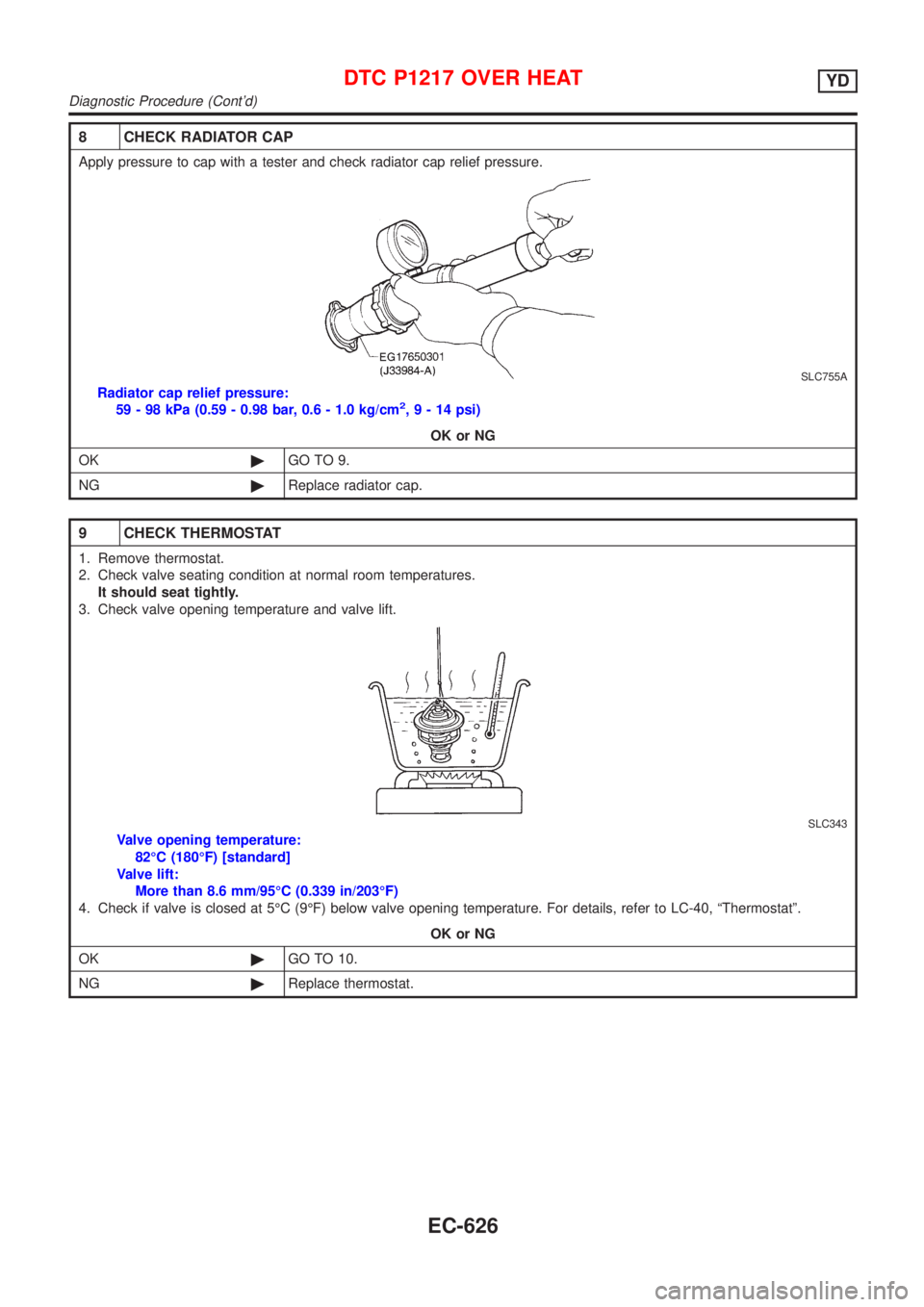
8 CHECK RADIATOR CAP
Apply pressure to cap with a tester and check radiator cap relief pressure.
SLC755A
Radiator cap relief pressure:
59 - 98 kPa (0.59 - 0.98 bar, 0.6 - 1.0 kg/cm2,9-14psi)
OK or NG
OK©GO TO 9.
NG©Replace radiator cap.
9 CHECK THERMOSTAT
1. Remove thermostat.
2. Check valve seating condition at normal room temperatures.
It should seat tightly.
3. Check valve opening temperature and valve lift.
SLC343
Valve opening temperature:
82ÉC (180ÉF) [standard]
Valve lift:
More than 8.6 mm/95ÉC (0.339 in/203ÉF)
4. Check if valve is closed at 5ÉC (9ÉF) below valve opening temperature. For details, refer to LC-40, ªThermostatº.
OK or NG
OK©GO TO 10.
NG©Replace thermostat.
DTC P1217 OVER HEATYD
Diagnostic Procedure (Cont'd)
EC-626
Page 929 of 2493
9 CHECK INTERMITTENT INCIDENT
1. Perform ªTROUBLE DIAGNOSIS FOR INTERMITTENT INCIDENTº, EC-559.
©INSPECTION END
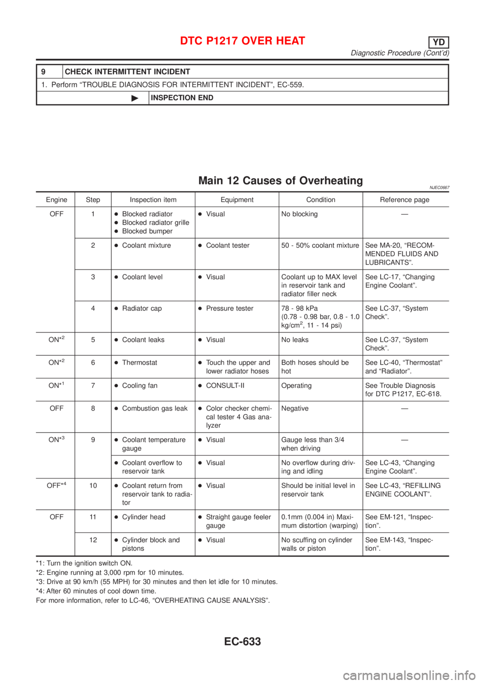
Main 12 Causes of OverheatingNJEC0667
Engine Step Inspection item Equipment Condition Reference page
OFF 1+Blocked radiator
+Blocked radiator grille
+Blocked bumper+Visual No blocking Ð
2+Coolant mixture+Coolant tester 50 - 50% coolant mixture See MA-20, ªRECOM-
MENDED FLUIDS AND
LUBRICANTSº.
3+Coolant level+Visual Coolant up to MAX level
in reservoir tank and
radiator filler neckSee LC-17, ªChanging
Engine Coolantº.
4+Radiator cap+Pressure tester 78 - 98 kPa
(0.78 - 0.98 bar, 0.8 - 1.0
kg/cm
2, 11 - 14 psi)See LC-37, ªSystem
Checkº.
ON*
25+Coolant leaks+Visual No leaks See LC-37, ªSystem
Checkº.
ON*
26+Thermostat+Touch the upper and
lower radiator hosesBoth hoses should be
hotSee LC-40, ªThermostatº
and ªRadiatorº.
ON*
17+Cooling fan+CONSULT-II Operating See Trouble Diagnosis
for DTC P1217, EC-618.
OFF 8+Combustion gas leak+Color checker chemi-
cal tester 4 Gas ana-
lyzerNegative Ð
ON*
39+Coolant temperature
gauge+Visual Gauge less than 3/4
when drivingÐ
+Coolant overflow to
reservoir tank+Visual No overflow during driv-
ing and idlingSee LC-43, ªChanging
Engine Coolantº.
OFF*
410+Coolant return from
reservoir tank to radia-
tor+Visual Should be initial level in
reservoir tankSee LC-43, ªREFILLING
ENGINE COOLANTº.
OFF 11+Cylinder head+Straight gauge feeler
gauge0.1mm (0.004 in) Maxi-
mum distortion (warping)See EM-121, ªInspec-
tionº.
12+Cylinder block and
pistons+Visual No scuffing on cylinder
walls or pistonSee EM-143, ªInspec-
tionº.
*1: Turn the ignition switch ON.
*2: Engine running at 3,000 rpm for 10 minutes.
*3: Drive at 90 km/h (55 MPH) for 30 minutes and then let idle for 10 minutes.
*4: After 60 minutes of cool down time.
For more information, refer to LC-46, ªOVERHEATING CAUSE ANALYSISº.
DTC P1217 OVER HEATYD
Diagnostic Procedure (Cont'd)
EC-633
Page 1201 of 2493
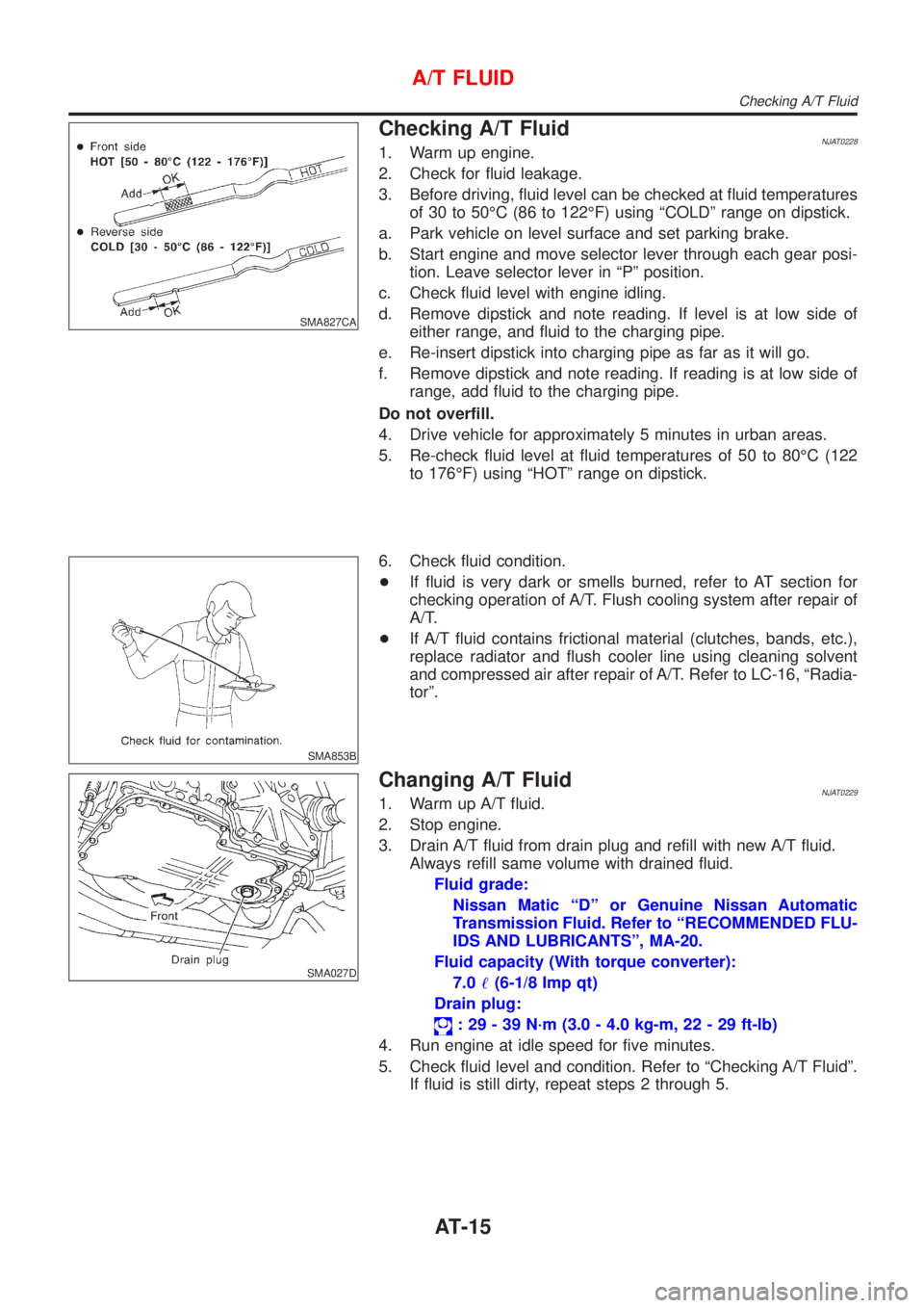
SMA827CA
Checking A/T FluidNJAT02281. Warm up engine.
2. Check for fluid leakage.
3. Before driving, fluid level can be checked at fluid temperatures
of 30 to 50ÉC (86 to 122ÉF) using ªCOLDº range on dipstick.
a. Park vehicle on level surface and set parking brake.
b. Start engine and move selector lever through each gear posi-
tion. Leave selector lever in ªPº position.
c. Check fluid level with engine idling.
d. Remove dipstick and note reading. If level is at low side of
either range, and fluid to the charging pipe.
e. Re-insert dipstick into charging pipe as far as it will go.
f. Remove dipstick and note reading. If reading is at low side of
range, add fluid to the charging pipe.
Do not overfill.
4. Drive vehicle for approximately 5 minutes in urban areas.
5. Re-check fluid level at fluid temperatures of 50 to 80ÉC (122
to 176ÉF) using ªHOTº range on dipstick.
SMA853B
6. Check fluid condition.
+If fluid is very dark or smells burned, refer to AT section for
checking operation of A/T. Flush cooling system after repair of
A/T.
+If A/T fluid contains frictional material (clutches, bands, etc.),
replace radiator and flush cooler line using cleaning solvent
and compressed air after repair of A/T. Refer to LC-16, ªRadia-
torº.
SMA027D
Changing A/T FluidNJAT02291. Warm up A/T fluid.
2. Stop engine.
3. Drain A/T fluid from drain plug and refill with new A/T fluid.
Always refill same volume with drained fluid.
Fluid grade:
Nissan Matic ªDº or Genuine Nissan Automatic
Transmission Fluid. Refer to ªRECOMMENDED FLU-
IDS AND LUBRICANTSº, MA-20.
Fluid capacity (With torque converter):
7.0!(6-1/8 Imp qt)
Drain plug:
: 29 - 39 N´m (3.0 - 4.0 kg-m, 22 - 29 ft-lb)
4. Run engine at idle speed for five minutes.
5. Check fluid level and condition. Refer to ªChecking A/T Fluidº.
If fluid is still dirty, repeat steps 2 through 5.
A/T FLUID
Checking A/T Fluid
AT-15
Page 2066 of 2493
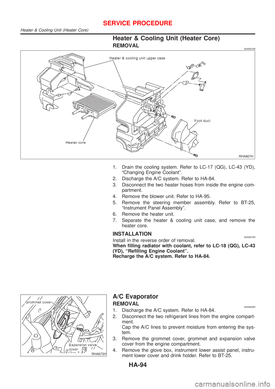
Heater & Cooling Unit (Heater Core)
REMOVALNJHA0193
RHA807H
1. Drain the cooling system. Refer to LC-17 (QG), LC-43 (YD),
ªChanging Engine Coolantº.
2. Discharge the A/C system. Refer to HA-84.
3. Disconnect the two heater hoses from inside the engine com-
partment.
4. Remove the blower unit. Refer to HA-95.
5. Remove the steering member assembly. Refer to BT-25,
ªInstrument Panel Assemblyº.
6. Remove the heater unit.
7. Separate the heater & cooling unit case, and remove the
heater core.
INSTALLATIONNJHA0194Install in the reverse order of removal.
When filling radiator with coolant, refer to LC-18 (QG), LC-43
(YD), ªRefilling Engine Coolantº.
Recharge the A/C system. Refer to HA-84.
RHA673H
A/C Evaporator
REMOVALNJHA02041. Discharge the A/C system. Refer to HA-84.
2. Disconnect the two refrigerant lines from the engine compart-
ment.
Cap the A/C lines to prevent moisture from entering the sys-
tem.
3. Remove the grommet cover, grommet and expansion valve
cover from the engine compartment.
4. Remove the glove box, instrument lower assist panel, instru-
ment lower cover and drink holder. Refer to BT-25.
SERVICE PROCEDURE
Heater & Cooling Unit (Heater Core)
HA-94