2001 NISSAN ALMERA N16 light
[x] Cancel search: lightPage 373 of 2493

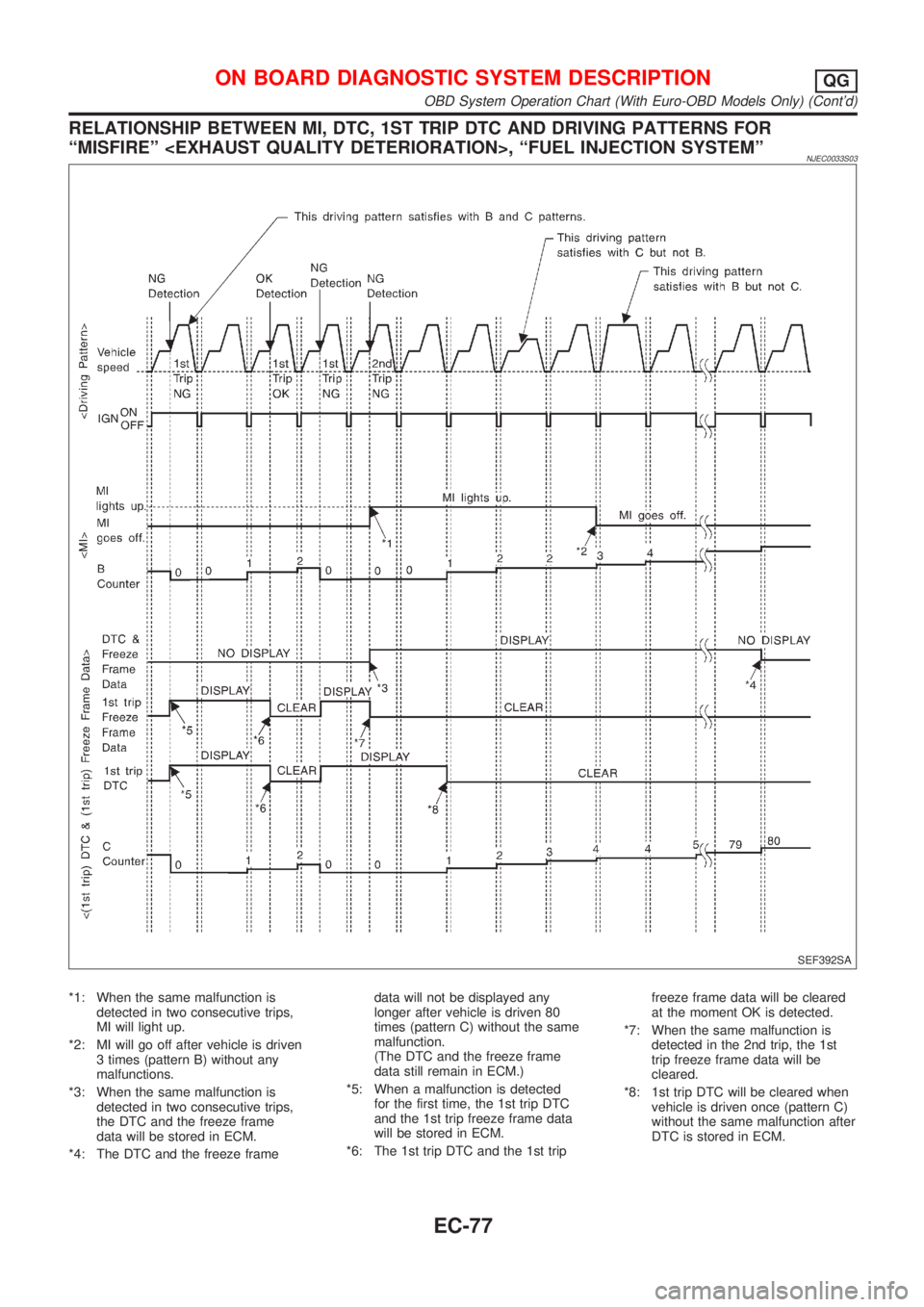
RELATIONSHIP BETWEEN MI, DTC, 1ST TRIP DTC AND DRIVING PATTERNS FOR
ªMISFIREº
NJEC0033S03
SEF392SA
*1: When the same malfunction is
detected in two consecutive trips,
MI will light up.
*2: MI will go off after vehicle is driven
3 times (pattern B) without any
malfunctions.
*3: When the same malfunction is
detected in two consecutive trips,
the DTC and the freeze frame
data will be stored in ECM.
*4: The DTC and the freeze framedata will not be displayed any
longer after vehicle is driven 80
times (pattern C) without the same
malfunction.
(The DTC and the freeze frame
data still remain in ECM.)
*5: When a malfunction is detected
for the first time, the 1st trip DTC
and the 1st trip freeze frame data
will be stored in ECM.
*6: The 1st trip DTC and the 1st tripfreeze frame data will be cleared
at the moment OK is detected.
*7: When the same malfunction is
detected in the 2nd trip, the 1st
trip freeze frame data will be
cleared.
*8: 1st trip DTC will be cleared when
vehicle is driven once (pattern C)
without the same malfunction after
DTC is stored in ECM.
ON BOARD DIAGNOSTIC SYSTEM DESCRIPTIONQG
OBD System Operation Chart (With Euro-OBD Models Only) (Cont'd)
EC-77
Page 375 of 2493

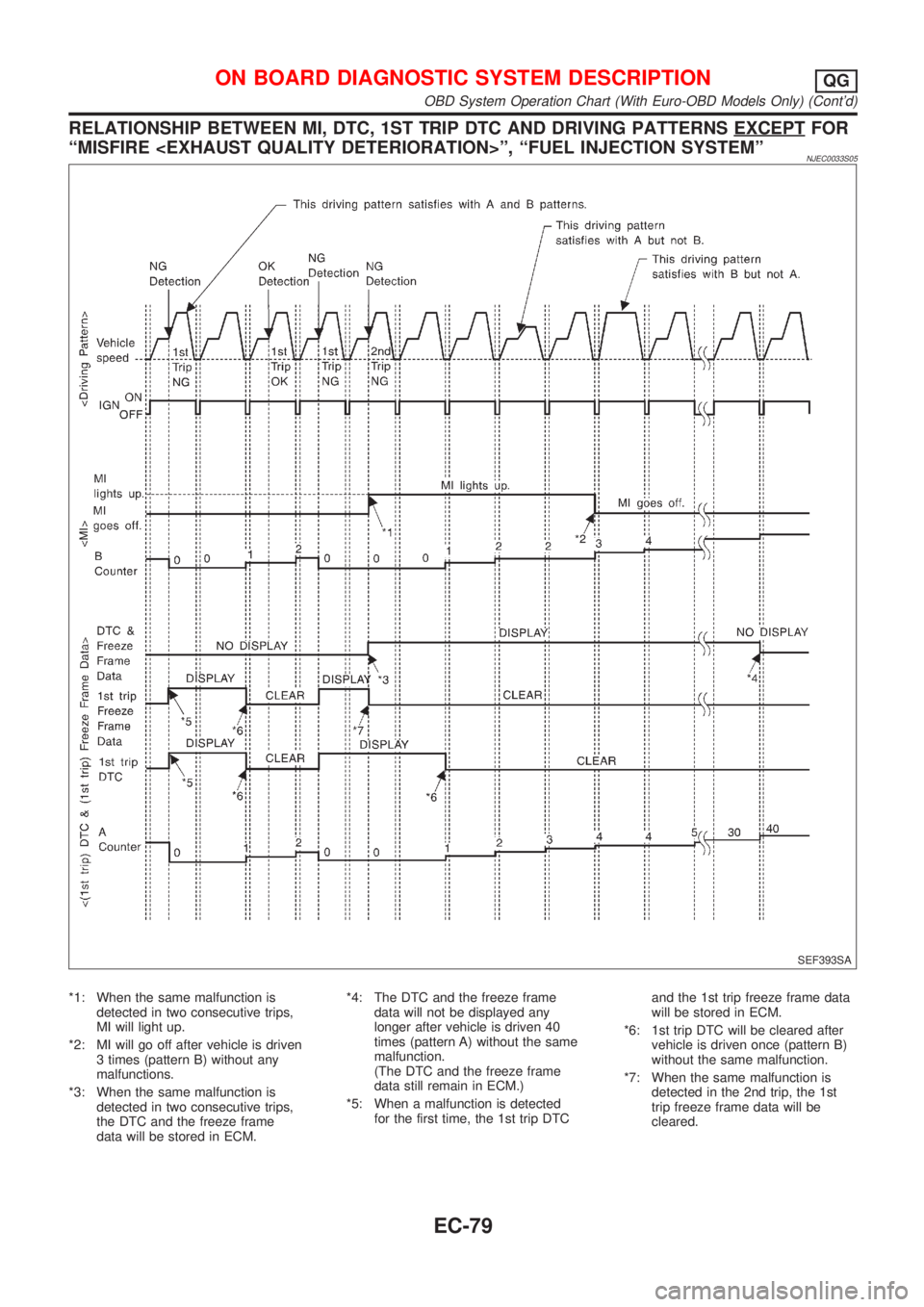
RELATIONSHIP BETWEEN MI, DTC, 1ST TRIP DTC AND DRIVING PATTERNS EXCEPTFOR
ªMISFIRE
NJEC0033S05
SEF393SA
*1: When the same malfunction is
detected in two consecutive trips,
MI will light up.
*2: MI will go off after vehicle is driven
3 times (pattern B) without any
malfunctions.
*3: When the same malfunction is
detected in two consecutive trips,
the DTC and the freeze frame
data will be stored in ECM.*4: The DTC and the freeze frame
data will not be displayed any
longer after vehicle is driven 40
times (pattern A) without the same
malfunction.
(The DTC and the freeze frame
data still remain in ECM.)
*5: When a malfunction is detected
for the first time, the 1st trip DTCand the 1st trip freeze frame data
will be stored in ECM.
*6: 1st trip DTC will be cleared after
vehicle is driven once (pattern B)
without the same malfunction.
*7: When the same malfunction is
detected in the 2nd trip, the 1st
trip freeze frame data will be
cleared.
ON BOARD DIAGNOSTIC SYSTEM DESCRIPTIONQG
OBD System Operation Chart (With Euro-OBD Models Only) (Cont'd)
EC-79
Page 380 of 2493

5) System readiness test (SRT) codes
6) Test values
7) Distance traveled while MI is activated.
8) Others
WORK SUPPORT MODENJEC0034S04
WORK ITEM CONDITION USAGE
TP SW/TP SEN IDLE POSI ADJ+FOLLOW THE BASIC INSPECTION INSTRUCTION IN
THE SERVICE MANUAL.When adjusting the idle throttle
position
FUEL PRESSURE RELEASE+FUEL PUMP WILL STOP BY TOUCHING ªSTARTº
DURING IDLING.
CRANK A FEW TIMES AFTER ENGINE STALLS.When releasing fuel pressure
from fuel line
IDLE AIR VOL LEARN+THE IDLE AIR VOLUME THAT KEEPS THE ENGINE
WITHIN THE SPECIFIED RANGE IS MEMORIZED IN
ECM.When learning the idle air volume
SELF-LEARNING CONT+THE COEFFICIENT OF SELF-LEARNING CONTROL
MIXTURE RATIO RETURNS TO THE ORIGINAL
COEFFICIENT.When clear the coefficient of self-
learnign control value
TARGET IDLE RPM ADJ*+IDLE CONDITION When setting target idle speed
TARGET IGNITION TIMING ADJ*+IDLE CONDITION When adjusting target ignition tim-
ing
After adjustment, confirm target
ignition timing with a timing light.
+If once the ªTARGET IDLE
RPM ADJº has been done, the
Idle Air Volume Learning proce-
dure will not be completed.
*: This function is not necessary in the usual service procedure.
SELF DIAGNOSTIC MODENJEC0034S05DTC and 1st Trip DTCNJEC0034S0501Regarding items of ªDTC and 1st trip DTCº, refer to
ªTROUBLE DIAGNOSIS Ð INDEXº, EC-10.
Freeze Frame Data and 1st Trip Freeze Frame DataNJEC0034S0502
Freeze frame data
item*Description
DIAG TROUBLE
CODE
[PXXXX]+Engine Control component part/control system has a trouble code, it is displayed as ªPXXXXº. (Refer to
ªAlphabetical & P No. Index for DTCº, EC-10.)
FUEL SYS-B1+ªFuel injection system statusº at the moment a malfunction is detected is displayed.
+One mode in the following is displayed.
ªMODE 2º: Open loop due to detected system malfunction
ªMODE 3º: Open loop due to driving conditions (power enrichment, deceleration enrichment)
ªMODE 4º: Closed loop - using oxygen sensor(s) as feedback for fuel control
ªMODE 5º: Open loop - has not yet satisfied condition to go to closed loop
CAL/LD VALUE [%]+The calculated load value at the moment a malfunction is detected is displayed.
COOLANT TEMP [ÉC]
or [ÉF]+The engine coolant temperature at the moment a malfunction is detected is displayed.
L-FUEL TRIM-B1 [%]+ªLong-term fuel trimº at the moment a malfunction is detected is displayed.
+The long-term fuel trim indicates much more gradual feedback compensation to the base fuel schedule
than short-term fuel trim.
S-FUEL TRIM-B1 [%]+ªShort-term fuel trimº at the moment a malfunction is detected is displayed.
+The short-term fuel trim indicates dynamic or instantaneous feedback compensation to the base fuel
schedule.
ON BOARD DIAGNOSTIC SYSTEM DESCRIPTIONQG
CONSULT-II (Cont'd)
EC-84
Page 382 of 2493
![NISSAN ALMERA N16 2001 Electronic Repair Manual Monitored item [Unit]ECM
input
signalsMain
signalsDescription Remarks
HO2S2 MNTR (B1)
[RICH/LEAN]j+Display of heated oxygen sensor 2 (rear)
signal:
RICH ... means the amount of oxygen after
three way NISSAN ALMERA N16 2001 Electronic Repair Manual Monitored item [Unit]ECM
input
signalsMain
signalsDescription Remarks
HO2S2 MNTR (B1)
[RICH/LEAN]j+Display of heated oxygen sensor 2 (rear)
signal:
RICH ... means the amount of oxygen after
three way](/manual-img/5/57351/w960_57351-381.png)
Monitored item [Unit]ECM
input
signalsMain
signalsDescription Remarks
HO2S2 MNTR (B1)
[RICH/LEAN]j+Display of heated oxygen sensor 2 (rear)
signal:
RICH ... means the amount of oxygen after
three way catalyst is relatively small.
LEAN ... means the amount of oxygen after
three way catalyst is relatively large.+When the engine is stopped, a cer-
tain value is indicated.
VHCL SPEED SE
[km/h] or [mph]jj+The vehicle speed computed from the
vehicle speed sensor signal is displayed.
BATTERY VOLT [V]j+The power supply voltage of ECM is dis-
played.
THRTL POS SEN [V]jj+The throttle position sensor signal voltage is
displayed.
FUEL T/TMP SE
[ÉC] or [ÉF]*+The fuel temperature judged from the fuel
tank temperature sensor signal voltage is
displayed.
INT/A TEMP SE
[ÉC] or [ÉF]j+The intake air temperature determined by
the signal voltage of the intake air tempera-
ture sensor is indicated.
EGR TEMP SEN [V]*jj+The signal voltage of the EGR temperature
sensor is displayed.
START SIGNAL
[ON/OFF]jj+Indicates [ON/OFF] condition from the
starter signal.+After starting the engine, [OFF] is
displayed regardless of the starter
signal.
CLSD THL POS
[ON/OFF]jj+Indicates idle position [ON/OFF] computed
by ECM according to the throttle position
sensor signal.
CLSD THL/P SW
[ON/OFF]*j+Indicates mechanical contact [ON/OFF]
condition of the closed throttle position
switch.
AIR COND SIG
[ON/OFF]jj+Indicates [ON/OFF] condition of the air con-
ditioner switch as determined by the air
conditioning signal.
P/N POSI SW
[ON/OFF]jj+Indicates [ON/OFF] condition from the PNP
switch signal.
PW/ST SIGNAL
[ON/OFF]jj+Indicates [ON/OFF] condition of the power
steering oil pressure switch determined by
the power steering oil pressure switch sig-
nal.
LOAD SIGNAL
[ON/OFF]jj+Indicates [ON/OFF] condition from the elec-
trical load signal and/or lighting switch.
ON ... rear defogger is operating and/or
lighting switch is on.
OFF ... rear defogger is not operating and
lighting switch is not on.
IGNITION SW
[ON/OFF]j+Indicates [ON/OFF] condition from ignition
switch.
HEATER FAN SW
[ON/OFF]j+Indicates [ON/OFF] condition from the
heater fan switch.
INJ PULSE-B1
[msec]j+Indicates the actual fuel injection pulse
width compensated by ECM according to
the input signals.+When the engine is stopped, a cer-
tain computed value is indicated.
ON BOARD DIAGNOSTIC SYSTEM DESCRIPTIONQG
CONSULT-II (Cont'd)
EC-86
Page 384 of 2493
![NISSAN ALMERA N16 2001 Electronic Repair Manual Monitored item [Unit]ECM
input
signalsMain
signalsDescription Remarks
IDL A/V LEARN+Display the condition of idle air volume
learning
YET ... Idle air volume learning has not
been performed yet.
CMPLT NISSAN ALMERA N16 2001 Electronic Repair Manual Monitored item [Unit]ECM
input
signalsMain
signalsDescription Remarks
IDL A/V LEARN+Display the condition of idle air volume
learning
YET ... Idle air volume learning has not
been performed yet.
CMPLT](/manual-img/5/57351/w960_57351-383.png)
Monitored item [Unit]ECM
input
signalsMain
signalsDescription Remarks
IDL A/V LEARN+Display the condition of idle air volume
learning
YET ... Idle air volume learning has not
been performed yet.
CMPLT ... Idle air volume learning has
already been performed successfully.
INCMP ... Idle air volume learning has not
been performed successfully.
TRVL AFTER MIL
[km] or [Mile]+Distance traveled while MI is activated
VOLTAGE [V]+Voltage measured by the voltage probe.
PULSE
[msec] or [Hz] or [%]+Pulse width, frequency or duty cycle mea-
sured by the pulse probe.+Only ª#º is displayed if item is
unable to be measured.
+Figures with ª#ºs are temporary
ones. They are the same figures as
an actual piece of data which was
just previously measured.
*: If so equipped
NOTE:
Any monitored item that does not match the vehicle being diagnosed is deleted from the display automatically.
DATA MONITOR (SPEC) MODENJEC0034S11
Monitored item [Unit]ECM
input
signalsMain
signalsDescription Remarks
MAS A/F SE-B1 [V]jj+The signal voltage of the mass air flow sen-
sor specification is displayed.+When the engine is running, speci-
fication range is indicated.
B/FUEL SCHDL
[msec]+ªBase fuel scheduleº indicates the fuel
injection pulse width programmed into
ECM, prior to any learned on board correc-
tion.+When the engine is running, speci-
fication range is indicated.
A/F ALPHA-B1 [%]j+Indicates the mean value of the air-fuel
ratio feedback correction factor per cycle.+When the engine is running, speci-
fication range is indicated.
+This data also includes the data for
the air-fuel ratio learning control.
NOTE:
Any monitored item that does not match the vehicle being diagnosed is deleted from the display automatically.
ACTIVE TEST MODENJEC0034S07
TEST ITEM CONDITION JUDGEMENT CHECK ITEM (REMEDY)
FUEL INJECTION+Engine: Return to the original
trouble condition
+Change the amount of fuel injec-
tion using CONSULT-II.If trouble symptom disappears, see
CHECK ITEM.+Harness and connector
+Fuel injectors
+Heated oxygen sensor 1 (front)
IGNITION TIMING+Engine: Return to the original
trouble condition
+Timing light: Set
+Retard the ignition timing using
CONSULT-II.If trouble symptom disappears, see
CHECK ITEM.+ªIdle Air Volume Leaningº (Refer
to EC-55.)
+Camshaft position sensor
(PHASE)
+Crankshaft position sensor
(POS)
+Engine component parts and
installing conditions
ON BOARD DIAGNOSTIC SYSTEM DESCRIPTIONQG
CONSULT-II (Cont'd)
EC-88
Page 394 of 2493

Basic InspectionNJEC1785MODELS WITH THROTTLE POSITION SWITCHNJEC1785S01Precaution:
Perform Basic Inspection without electrical or mechanical
loads applied;
+Headlamp switch is OFF,
On vehicle equipped with daytime light systems, set lighting
switch to the 1st position to light only small lamps.
+Air conditioner switch is OFF,
+Rear window defogger switch is OFF,
+Steering wheel is in the straight-ahead position, etc.
1 INSPECTION START
1. Check service records for any recent repairs that may indicate a related problem, or a current need for scheduled
maintenance.
2. Open engine hood and check the following:
+Harness connectors for improper connections
+Vacuum hoses for splits, kinks and improper connections
+Wiring for improper connections, pinches and cuts
+Air cleaner clogging
+Hoses and ducts for leaks
SEF983U
©GO TO 2.
2 CHECK THROTTLE OPENER OPERATION-I
Confirm that there is a clearance between throttle drum and stopper.
SEF850Y
OK or NG
OK©GO TO 4.
NG©GO TO 3.
TROUBLE DIAGNOSIS Ð BASIC INSPECTIONQG
Basic Inspection
EC-98
Page 407 of 2493

27 CHECK TARGET IDLE SPEED AGAIN
With CONSULT-II
1. Start engine and warm it up to normal operating temperature.
2. Select ªENG SPEEDº in ªDATA MONITORº mode with CONSULT-II.
3. Check idle speed.
M/T: 700±50 rpm
A/T: 800±50 rpm (in ªPº or ªNº position)
Without CONSULT-II
1. Start engine and warm it up to normal operating temperature.
2. Check idle speed.
M/T: 700±50 rpm
A/T: 800±50 rpm (in ªPº or ªNº position)
OK or NG
OK©GO TO 29.
NG©GO TO 28.
28 CHECK ECM FUNCTION
1. Substitute another known-good ECM to check ECM function. (ECM may be the cause of a problem, but this is rarely
the case.)
2. Perform initialization of NATS system and registration of NATS ignition key IDs. Refer to ªNATS (Nissan Anti-Theft
System)º, EC-72.
©GO TO 22.
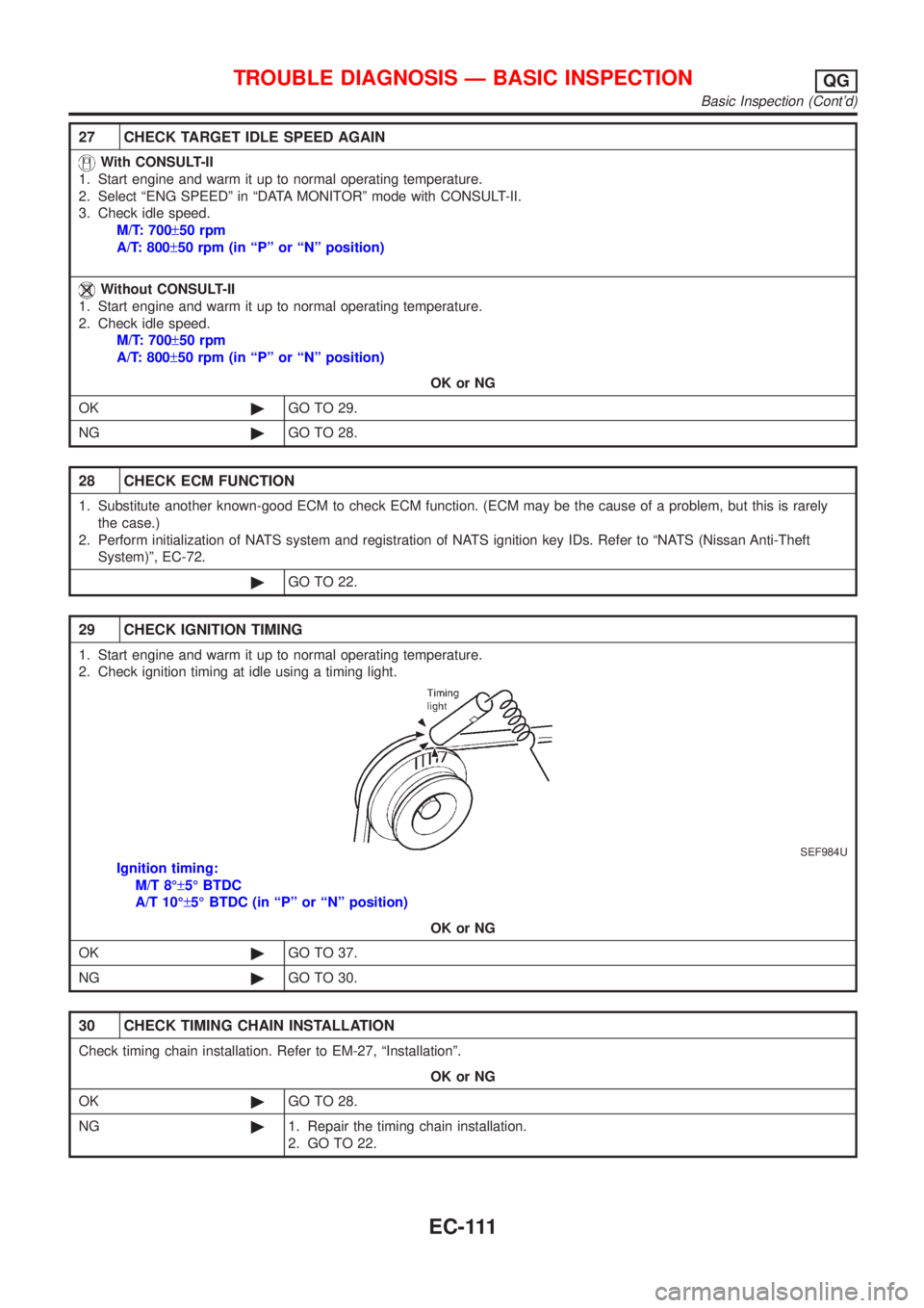
29 CHECK IGNITION TIMING
1. Start engine and warm it up to normal operating temperature.
2. Check ignition timing at idle using a timing light.
SEF984U
Ignition timing:
M/T 8ɱ5É BTDC
A/T 10ɱ5É BTDC (in ªPº or ªNº position)
OK or NG
OK©GO TO 37.
NG©GO TO 30.
30 CHECK TIMING CHAIN INSTALLATION
Check timing chain installation. Refer to EM-27, ªInstallationº.
OK or NG
OK©GO TO 28.
NG©1. Repair the timing chain installation.
2. GO TO 22.
TROUBLE DIAGNOSIS Ð BASIC INSPECTIONQG
Basic Inspection (Cont'd)
EC-111
Page 408 of 2493

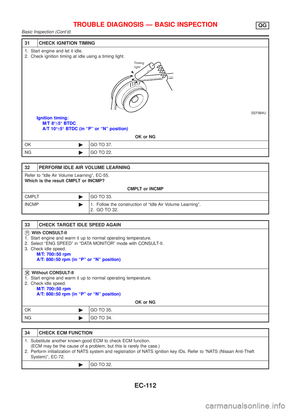
31 CHECK IGNITION TIMING
1. Start engine and let it idle.
2. Check ignition timing at idle using a timing light.
SEF984U
Ignition timing:
M/T 8ɱ5É BTDC
A/T 10ɱ5É BTDC (in ªPº or ªNº position)
OK or NG
OK©GO TO 37.
NG©GO TO 22.
32 PERFORM IDLE AIR VOLUME LEARNING
Refer to ªIdle Air Volume Learningº, EC-55.
Which is the result CMPLT or INCMP?
CMPLT or INCMP
CMPLT©GO TO 33.
INCMP©1. Follow the construction of ªIdle Air Volume Learningº.
2. GO TO 32.
33 CHECK TARGET IDLE SPEED AGAIN
With CONSULT-II
1. Start engine and warm it up to normal operating temperature.
2. Select ªENG SPEEDº in ªDATA MONITORº mode with CONSULT-II.
3. Check idle speed.
M/T: 700±50 rpm
A/T: 800±50 rpm (in ªPº or ªNº position)
Without CONSULT-II
1. Start engine and warm it up to normal operating temperature.
2. Check idle speed.
M/T: 700±50 rpm
A/T: 800±50 rpm (in ªPº or ªNº position)
OK or NG
OK©GO TO 35.
NG©GO TO 34.
34 CHECK ECM FUNCTION
1. Substitute another known-good ECM to check ECM function.
(ECM may be the cause of a problem, but this is rarely the case.)
2. Perform initialization of NATS system and registration of NATS ignition key IDs. Refer to ªNATS (Nissan Anti-Theft
System)º, EC-72.
©GO TO 32.
TROUBLE DIAGNOSIS Ð BASIC INSPECTIONQG
Basic Inspection (Cont'd)
EC-112