Page 2074 of 2493
Idle Air Control Valve (IACV) Ð Auxiliary Air
Control (AAC) Valve
INSPECTIONNJHA0199+Refer to EC-313 (QG), ªSystem Descriptionº.
RHA680H
Ventilation Air Filter
FUNCTIONNJHA0171Air inside passenger compartment is kept clean at either recircula-
tion or fresh mode by installing ventilation air filter into cooling unit.
SHA868E
REPLACEMENT TIMINGNJHA0172Replace ventilation air filter.
Refer to MA-8, ªPERIODIC MAINTENANCEº.
Caution label is fixed inside the glove box.
RHA681H
REPLACEMENT PROCEDURENJHA0173+Remove glove box.
+Remove filter cover.
+Take out the ventilation air filter from blower unit.
+Replace with new one and reinstall on blower unit.
+Reinstall glove box.
SERVICE PROCEDURE
Idle Air Control Valve (IACV) Ð Auxiliary Air Control (AAC) Valve
HA-102
Page 2075 of 2493
CompressorNJHA0174
ModelCALSONIC make CSV613
TypeSwash plate (Variable displacement)
Displacement cm
3(cu in)/rev.6.0 - 125 (0.37 - 7.63)
Direction of rotationClockwise (viewed from drive end)
Drive beltQG engine model: Poly V
YD engine model: Type A
LubricantNJHA0175
ModelCALSONIC make CSV613
NameNissan A/C System Oil Type S
Part numberKLH00-PAGS0
Capacity
m!(Imp fl oz)Total in system 180 (6.3) - 200 (7.0)
Compressor (Service part) charging amount 180 (6.3) - 200 (7.0)
RefrigerantNJHA0176
TypeHFC-134a (R-134a)
Capacity kg (lb)0.45 - 0.55 (0.99 - 1.21)
Engine Idling Speed (When A/C is On)NJHA0177+Refer to EC-489 (QG), EC-702 (YD), ªIdle Speed and Ignition Timingº.
Belt TensionNJHA0178+Refer to EM-15 (QG), EM-84 (YD), ªChecking Drive Beltsº.
SERVICE DATA AND SPECIFICATIONS (SDS)
Compressor
HA-103
Page 2076 of 2493
SERVICE DATA AND SPECIFICATIONS (SDS)
Belt Tension (Cont'd)
HA-104
Page 2077 of 2493

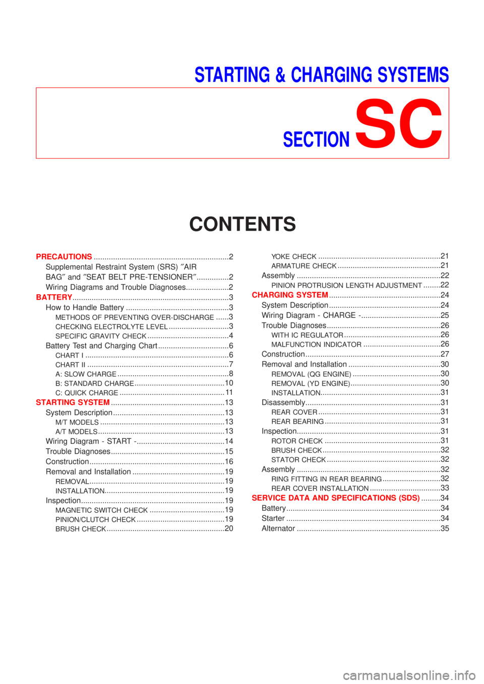
STARTING & CHARGING SYSTEMS
SECTION
SC
CONTENTS
PRECAUTIONS...............................................................2
Supplemental Restraint System (SRS)²AIR
BAG²and²SEAT BELT PRE-TENSIONER²...............2
Wiring Diagrams and Trouble Diagnoses....................2
BATTERY.........................................................................3
How to Handle Battery ................................................3
METHODS OF PREVENTING OVER-DISCHARGE......3
CHECKING ELECTROLYTE LEVEL............................3
SPECIFIC GRAVITY CHECK......................................4
Battery Test and Charging Chart .................................6
CHART I...................................................................6
CHART II..................................................................7
A: SLOW CHARGE....................................................8
B: STANDARD CHARGE..........................................10
C: QUICK CHARGE................................................. 11
STARTING SYSTEM.....................................................13
System Description ....................................................13
M/T MODELS..........................................................13
A/T MODELS...........................................................13
Wiring Diagram - START -.........................................14
Trouble Diagnoses.....................................................15
Construction ...............................................................16
Removal and Installation ...........................................19
REMOVAL...............................................................19
INSTALLATION........................................................19
Inspection...................................................................19
MAGNETIC SWITCH CHECK...................................19
PINION/CLUTCH CHECK.........................................19
BRUSH CHECK.......................................................20
YOKE CHECK.........................................................21
ARMATURE CHECK................................................21
Assembly ...................................................................22
PINION PROTRUSION LENGTH ADJUSTMENT........22
CHARGING SYSTEM....................................................24
System Description ....................................................24
Wiring Diagram - CHARGE -.....................................25
Trouble Diagnoses.....................................................26
WITH IC REGULATOR.............................................26
MALFUNCTION INDICATOR....................................26
Construction ...............................................................27
Removal and Installation ...........................................30
REMOVAL (QG ENGINE).........................................30
REMOVAL (YD ENGINE)..........................................30
INSTALLATION........................................................31
Disassembly...............................................................31
REAR COVER.........................................................31
REAR BEARING......................................................31
Inspection...................................................................31
ROTOR CHECK......................................................31
BRUSH CHECK.......................................................32
STATOR CHECK.....................................................32
Assembly ...................................................................32
RING FITTING IN REAR BEARING...........................32
REAR COVER INSTALLATION.................................33
SERVICE DATA AND SPECIFICATIONS (SDS).........34
Battery........................................................................34
Starter ........................................................................34
Alternator ...................................................................35
Page 2078 of 2493

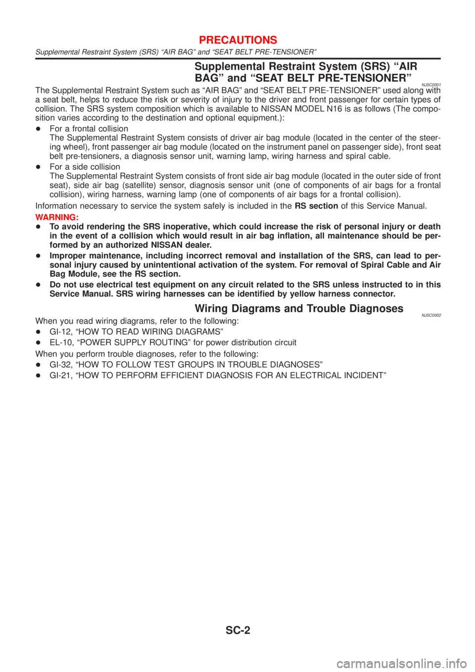
Supplemental Restraint System (SRS) ªAIR
BAGº and ªSEAT BELT PRE-TENSIONERº
NJSC0001The Supplemental Restraint System such as ªAIR BAGº and ªSEAT BELT PRE-TENSIONERº used along with
a seat belt, helps to reduce the risk or severity of injury to the driver and front passenger for certain types of
collision. The SRS system composition which is available to NISSAN MODEL N16 is as follows (The compo-
sition varies according to the destination and optional equipment.):
+For a frontal collision
The Supplemental Restraint System consists of driver air bag module (located in the center of the steer-
ing wheel), front passenger air bag module (located on the instrument panel on passenger side), front seat
belt pre-tensioners, a diagnosis sensor unit, warning lamp, wiring harness and spiral cable.
+For a side collision
The Supplemental Restraint System consists of front side air bag module (located in the outer side of front
seat), side air bag (satellite) sensor, diagnosis sensor unit (one of components of air bags for a frontal
collision), wiring harness, warning lamp (one of components of air bags for a frontal collision).
Information necessary to service the system safely is included in theRS sectionof this Service Manual.
WARNING:
+To avoid rendering the SRS inoperative, which could increase the risk of personal injury or death
in the event of a collision which would result in air bag inflation, all maintenance should be per-
formed by an authorized NISSAN dealer.
+Improper maintenance, including incorrect removal and installation of the SRS, can lead to per-
sonal injury caused by unintentional activation of the system. For removal of Spiral Cable and Air
Bag Module, see the RS section.
+Do not use electrical test equipment on any circuit related to the SRS unless instructed to in this
Service Manual. SRS wiring harnesses can be identified by yellow harness connector.
Wiring Diagrams and Trouble DiagnosesNJSC0002When you read wiring diagrams, refer to the following:
+GI-12, ªHOW TO READ WIRING DIAGRAMSº
+EL-10, ªPOWER SUPPLY ROUTINGº for power distribution circuit
When you perform trouble diagnoses, refer to the following:
+GI-32, ªHOW TO FOLLOW TEST GROUPS IN TROUBLE DIAGNOSESº
+GI-21, ªHOW TO PERFORM EFFICIENT DIAGNOSIS FOR AN ELECTRICAL INCIDENTº
PRECAUTIONS
Supplemental Restraint System (SRS) ªAIR BAGº and ªSEAT BELT PRE-TENSIONERº
SC-2
Page 2110 of 2493

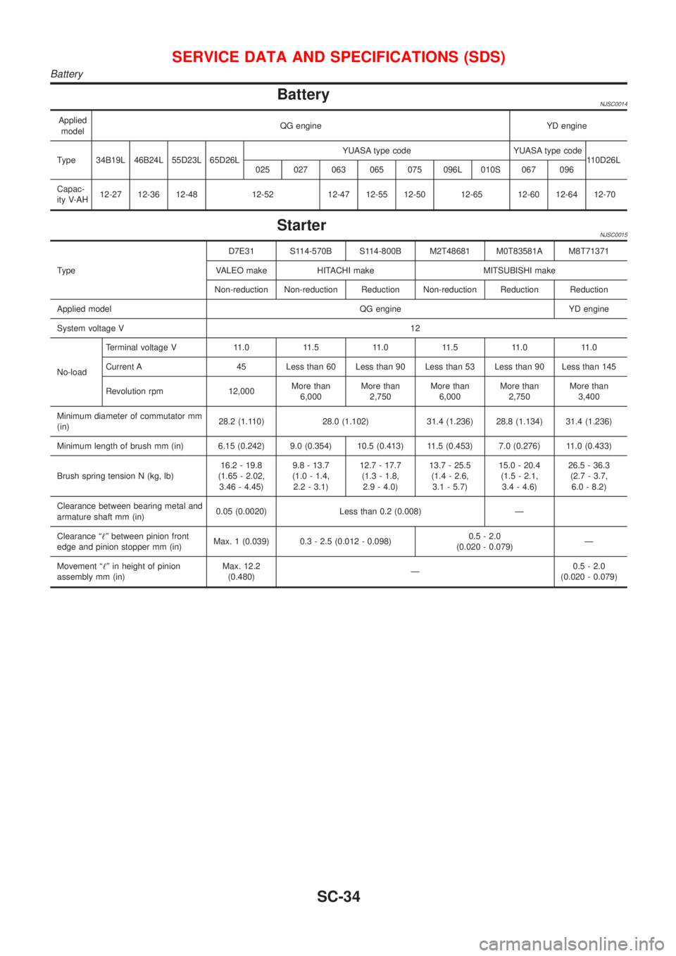
BatteryNJSC0014
Applied
modelQG engine YD engine
Type 34B19L 46B24L 55D23L 65D26LYUASA type code YUASA type code
110D26L
025 027 063 065 075 096L 010S 067 096
Capac-
ity V-AH12-27 12-36 12-48 12-52 12-47 12-55 12-50 12-65 12-60 12-64 12-70
StarterNJSC0015
TypeD7E31 S114-570B S114-800B M2T48681 M0T83581A M8T71371
VALEO make HITACHI make MITSUBISHI make
Non-reduction Non-reduction Reduction Non-reduction Reduction Reduction
Applied model QG engine YD engine
System voltage V12
No-loadTerminal voltage V 11.0 11.5 11.0 11.5 11.0 11.0
Current A 45 Less than 60 Less than 90 Less than 53 Less than 90 Less than 145
Revolution rpm 12,000More than
6,000More than
2,750More than
6,000More than
2,750More than
3,400
Minimum diameter of commutator mm
(in)28.2 (1.110) 28.0 (1.102) 31.4 (1.236) 28.8 (1.134) 31.4 (1.236)
Minimum length of brush mm (in) 6.15 (0.242) 9.0 (0.354) 10.5 (0.413) 11.5 (0.453) 7.0 (0.276) 11.0 (0.433)
Brush spring tension N (kg, lb)16.2 - 19.8
(1.65 - 2.02,
3.46 - 4.45)9.8 - 13.7
(1.0 - 1.4,
2.2 - 3.1)12.7 - 17.7
(1.3 - 1.8,
2.9 - 4.0)13.7 - 25.5
(1.4 - 2.6,
3.1 - 5.7)15.0 - 20.4
(1.5 - 2.1,
3.4 - 4.6)26.5 - 36.3
(2.7 - 3.7,
6.0 - 8.2)
Clearance between bearing metal and
armature shaft mm (in)0.05 (0.0020) Less than 0.2 (0.008) Ð
Clearance ª!º between pinion front
edge and pinion stopper mm (in)Max. 1 (0.039) 0.3 - 2.5 (0.012 - 0.098)0.5 - 2.0
(0.020 - 0.079)Ð
Movement ª!º in height of pinion
assembly mm (in)Max. 12.2
(0.480)Ð0.5 - 2.0
(0.020 - 0.079)
SERVICE DATA AND SPECIFICATIONS (SDS)
Battery
SC-34
Page 2111 of 2493

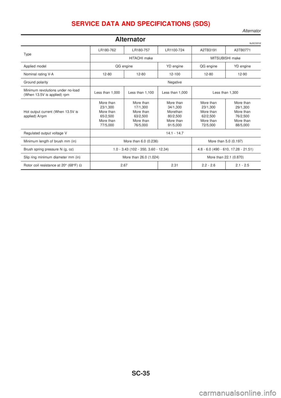
AlternatorNJSC0016
TypeLR180-762 LR180-757 LR1100-724 A2TB3191 A3TB0771
HITACHI make MITSUBISHI make
Applied model QG engine YD engine QG engine YD engine
Nominal rating V-A 12-80 12-80 12-100 12-80 12-90
Ground polarityNegative
Minimum revolutions under no-load
(When 13.5V is applied) rpmLess than 1,000 Less than 1,100 Less than 1,000 Less than 1,300
Hot output current (When 13.5V is
applied) A/rpmMore than
23/1,300
More than
65/2,500
More than
77/5,000More than
17/1,300
More than
63/2,500
More than
76/5,000More than
34/1,300
Morethan
80/2,500
More than
91/5,000More than
23/1,300
More than
62/2,500
More than
72/5,000More than
29/1,300
More than
76/2,500
More than
88/5,000
Regulated output voltage V 14.1 - 14.7
Minimum length of brush mm (in) More than 6.0 (0.236) More than 5.0 (0.197)
Brush spring pressure N (g, oz) 1.0 - 3.43 (102 - 350, 3.60 - 12.34) 4.8 - 6.0 (490 - 610, 17.28 - 21.51)
Slip ring minimum diameter mm (in) More than 26.0 (1.024) More than 22.1 (0.870)
Rotor coil resistance at 20É (68ÉF)W2.67 2.31 2.2 - 2.6 2.1 - 2.5
SERVICE DATA AND SPECIFICATIONS (SDS)
Alternator
SC-35
Page 2112 of 2493
SERVICE DATA AND SPECIFICATIONS (SDS)
Alternator (Cont'd)
SC-36