2001 NISSAN ALMERA N16 power steering fluid
[x] Cancel search: power steering fluidPage 1813 of 2493

SST090B
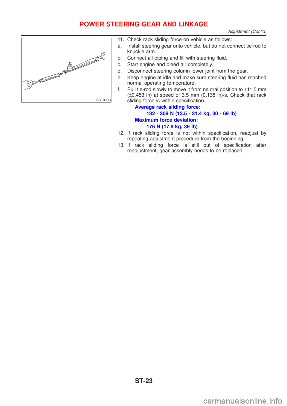
11. Check rack sliding force on vehicle as follows:
a. Install steering gear onto vehicle, but do not connect tie-rod to
knuckle arm.
b. Connect all piping and fill with steering fluid.
c. Start engine and bleed air completely.
d. Disconnect steering column lower joint from the gear.
e. Keep engine at idle and make sure steering fluid has reached
normal operating temperature.
f. Pull tie-rod slowly to move it from neutral position to±11.5 mm
(±0.453 in) at speed of 3.5 mm (0.138 in)/s. Check that rack
sliding force is within specification.
Average rack sliding force:
132 - 308 N (13.5 - 31.4 kg, 30 - 69 lb)
Maximum force deviation:
176 N (17.9 kg, 39 lb)
12. If rack sliding force is not within specification, readjust by
repeating adjustment procedure from the beginning.
13. If rack sliding force is still out of specification after
readjustment, gear assembly needs to be replaced.
POWER STEERING GEAR AND LINKAGE
Adjustment (Cont'd)
ST-23
Page 1820 of 2493

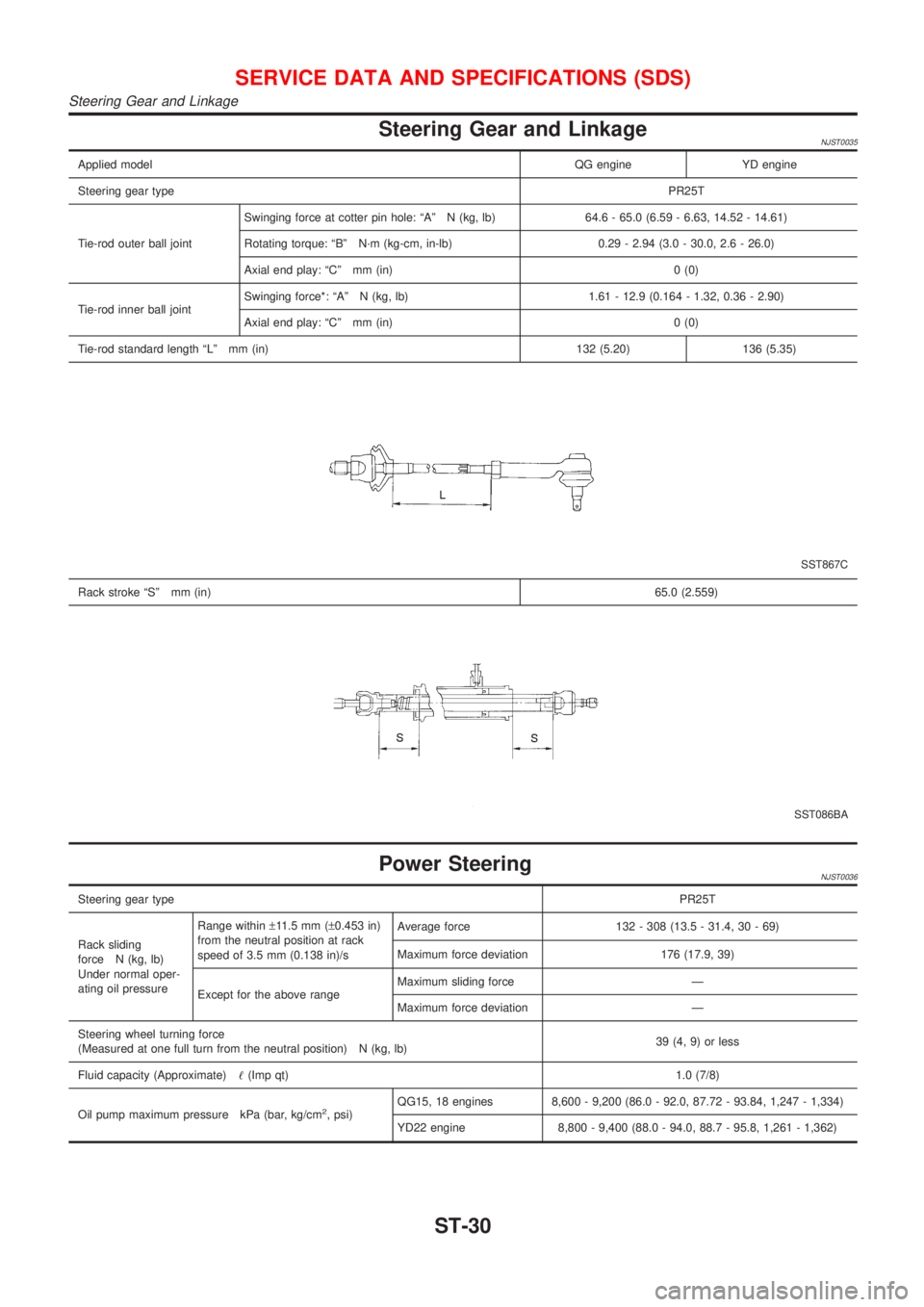
Steering Gear and LinkageNJST0035
Applied modelQG engine YD engine
Steering gear typePR25T
Tie-rod outer ball jointSwinging force at cotter pin hole: ªAº N (kg, lb) 64.6 - 65.0 (6.59 - 6.63, 14.52 - 14.61)
Rotating torque: ªBº N´m (kg-cm, in-lb) 0.29 - 2.94 (3.0 - 30.0, 2.6 - 26.0)
Axial end play: ªCº mm (in) 0 (0)
Tie-rod inner ball jointSwinging force*: ªAº N (kg, lb) 1.61 - 12.9 (0.164 - 1.32, 0.36 - 2.90)
Axial end play: ªCº mm (in) 0 (0)
Tie-rod standard length ªLº mm (in) 132 (5.20) 136 (5.35)
SST867C
Rack stroke ªSº mm (in)65.0 (2.559)
SST086BA
Power SteeringNJST0036
Steering gear typePR25T
Rack sliding
force N (kg, lb)
Under normal oper-
ating oil pressureRange within±11.5 mm (±0.453 in)
from the neutral position at rack
speed of 3.5 mm (0.138 in)/sAverage force 132 - 308 (13.5 - 31.4, 30 - 69)
Maximum force deviation 176 (17.9, 39)
Except for the above rangeMaximum sliding force Ð
Maximum force deviation Ð
Steering wheel turning force
(Measured at one full turn from the neutral position) N (kg, lb)39 (4, 9) or less
Fluid capacity (Approximate)!(Imp qt)1.0 (7/8)
Oil pump maximum pressure kPa (bar, kg/cm
2, psi)QG15, 18 engines 8,600 - 9,200 (86.0 - 92.0, 87.72 - 93.84, 1,247 - 1,334)
YD22 engine 8,800 - 9,400 (88.0 - 94.0, 88.7 - 95.8, 1,261 - 1,362)
SERVICE DATA AND SPECIFICATIONS (SDS)
Steering Gear and Linkage
ST-30
Page 2486 of 2493

O
Oil pan (engine) .................................. EM-19, 88
Oil pressure (engine) ............................ LC-5, 27
Oil pump (A/T) ......................................... AT-371
Oil pump (engine) ................................. LC-5, 27
Oil pump regulator valve (engine) ......... LC-7, 29
Oil seal replacement (engine) .................. EM-31
On board diagnostic system ............. EC-57, 522
Operating cylinder (clutch) ........................ CL-14
Overdrive control switch .......................... AT-333
Overrun clutch .......................................... AT-399
P
PCV (positive crankcase ventilation) ....... EC-37,
508
PGC/V - Wiring diagram ................. EC-306, 413
PNP/SW - Wiring diagram ...... EC-366, 442, 696
POWER - Wiring diagram ......................... EL-12
PST/SW - Wiring diagram ....................... EC-471
Park/Neutral position switch ... EC-364, 441, 696
Park/neutral position switch (A/T) ............ AT-181
Park/neutral position switch (M/T) ............ MT-21
Parking brake control ................................ BR-47
Parking lamp .............................................. EL-53
Piston assembly ............................... EM-60, 154
Piston pin inspection ........................ EM-54, 144
Piston ring inspection ....................... EM-54, 144
Piston to bore clearance .................. EM-56, 146
Power antenna ........................................ EL-162
Power door lock ....................................... EL-177
Power door mirror .................................... EL-167
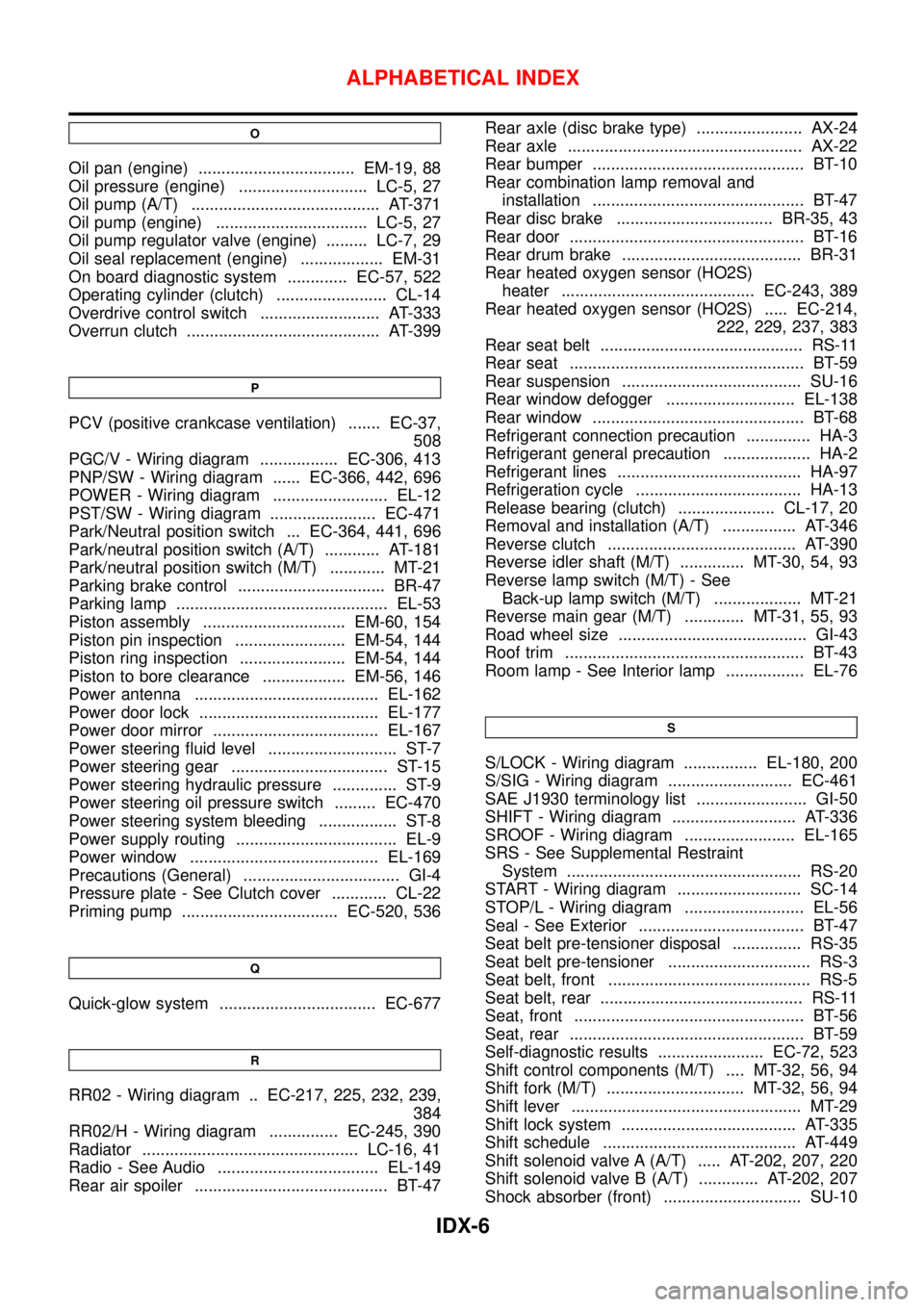
Power steering fluid level ............................ ST-7
Power steering gear .................................. ST-15
Power steering hydraulic pressure .............. ST-9
Power steering oil pressure switch ......... EC-470
Power steering system bleeding ................. ST-8
Power supply routing ................................... EL-9
Power window ......................................... EL-169
Precautions (General) .................................. GI-4
Pressure plate - See Clutch cover ............ CL-22
Priming pump .................................. EC-520, 536
Q
Quick-glow system .................................. EC-677
R
RR02 - Wiring diagram .. EC-217, 225, 232, 239,
384
RR02/H - Wiring diagram ............... EC-245, 390
Radiator ............................................... LC-16, 41
Radio - See Audio ................................... EL-149
Rear air spoiler .......................................... BT-47Rear axle (disc brake type) ....................... AX-24
Rear axle ................................................... AX-22
Rear bumper .............................................. BT-10
Rear combination lamp removal and
installation .............................................. BT-47
Rear disc brake .................................. BR-35, 43
Rear door ................................................... BT-16
Rear drum brake ....................................... BR-31
Rear heated oxygen sensor (HO2S)
heater .......................................... EC-243, 389
Rear heated oxygen sensor (HO2S) ..... EC-214,
222, 229, 237, 383
Rear seat belt ............................................ RS-11
Rear seat ................................................... BT-59
Rear suspension ....................................... SU-16
Rear window defogger ............................ EL-138
Rear window .............................................. BT-68
Refrigerant connection precaution .............. HA-3
Refrigerant general precaution ................... HA-2
Refrigerant lines ........................................ HA-97
Refrigeration cycle .................................... HA-13
Release bearing (clutch) ..................... CL-17, 20
Removal and installation (A/T) ................ AT-346
Reverse clutch ......................................... AT-390
Reverse idler shaft (M/T) .............. MT-30, 54, 93
Reverse lamp switch (M/T) - See
Back-up lamp switch (M/T) ................... MT-21
Reverse main gear (M/T) ............. MT-31, 55, 93
Road wheel size ......................................... GI-43
Roof trim .................................................... BT-43
Room lamp - See Interior lamp ................. EL-76
S
S/LOCK - Wiring diagram ................ EL-180, 200
S/SIG - Wiring diagram ........................... EC-461
SAE J1930 terminology list ........................ GI-50
SHIFT - Wiring diagram ........................... AT-336
SROOF - Wiring diagram ........................ EL-165
SRS - See Supplemental Restraint
System ................................................... RS-20
START - Wiring diagram ........................... SC-14
STOP/L - Wiring diagram .......................... EL-56
Seal - See Exterior .................................... BT-47
Seat belt pre-tensioner disposal ............... RS-35
Seat belt pre-tensioner ............................... RS-3
Seat belt, front ............................................ RS-5
Seat belt, rear ............................................ RS-11
Seat, front .................................................. BT-56
Seat, rear ................................................... BT-59
Self-diagnostic results ....................... EC-72, 523
Shift control components (M/T) .... MT-32, 56, 94
Shift fork (M/T) .............................. MT-32, 56, 94
Shift lever .................................................. MT-29
Shift lock system ...................................... AT-335
Shift schedule .......................................... AT-449
Shift solenoid valve A (A/T) ..... AT-202, 207, 220
Shift solenoid valve B (A/T) ............. AT-202, 207
Shock absorber (front) .............................. SU-10
ALPHABETICAL INDEX
IDX-6