Page 716 of 2493
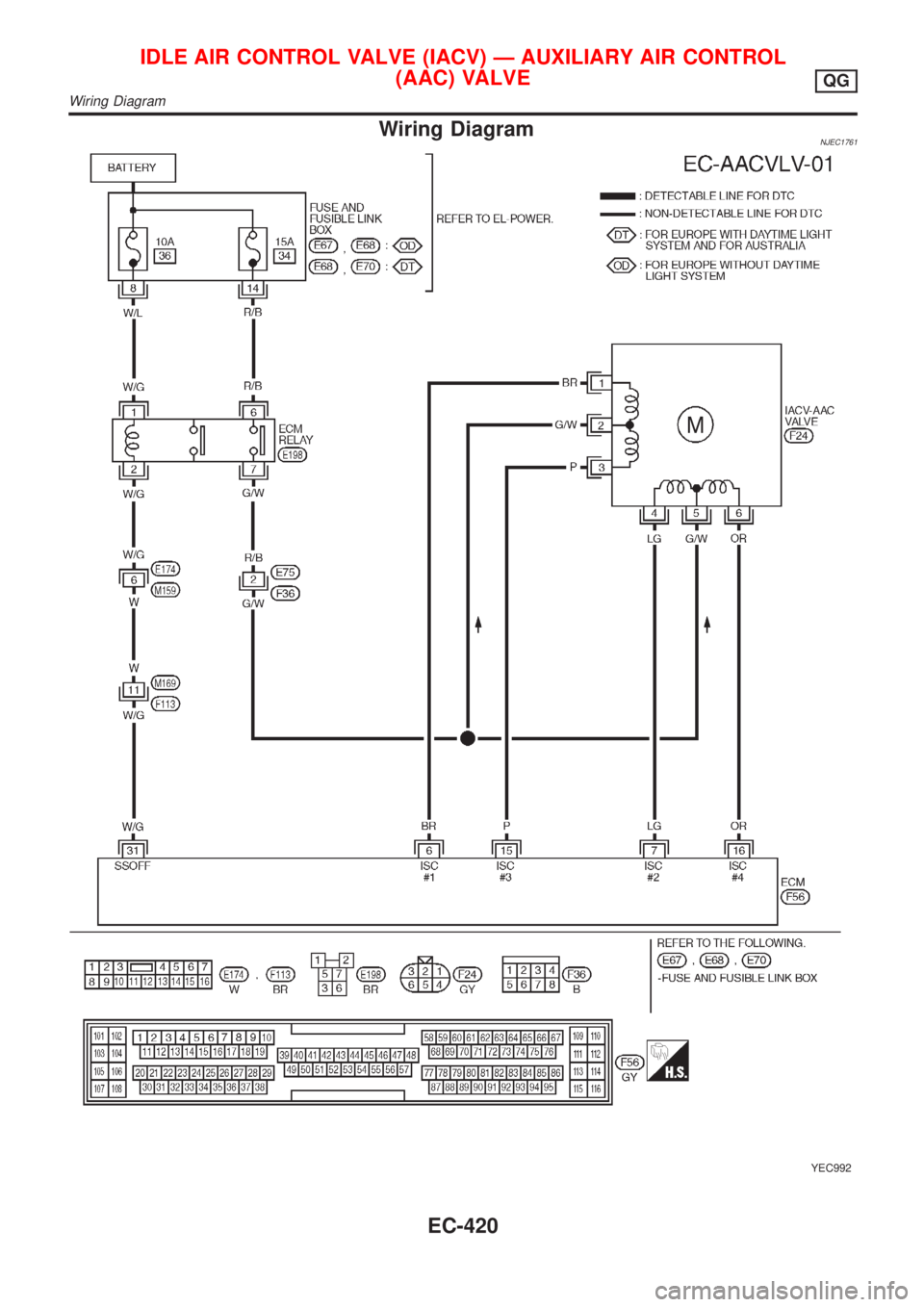
Wiring DiagramNJEC1761
YEC992
IDLE AIR CONTROL VALVE (IACV) Ð AUXILIARY AIR CONTROL
(AAC) VALVE
QG
Wiring Diagram
EC-420
Page 717 of 2493
Diagnostic ProcedureNJEC1762
1 CHECK OVERALL FUNCTION
1. Turn ignition switch ªOFFº.
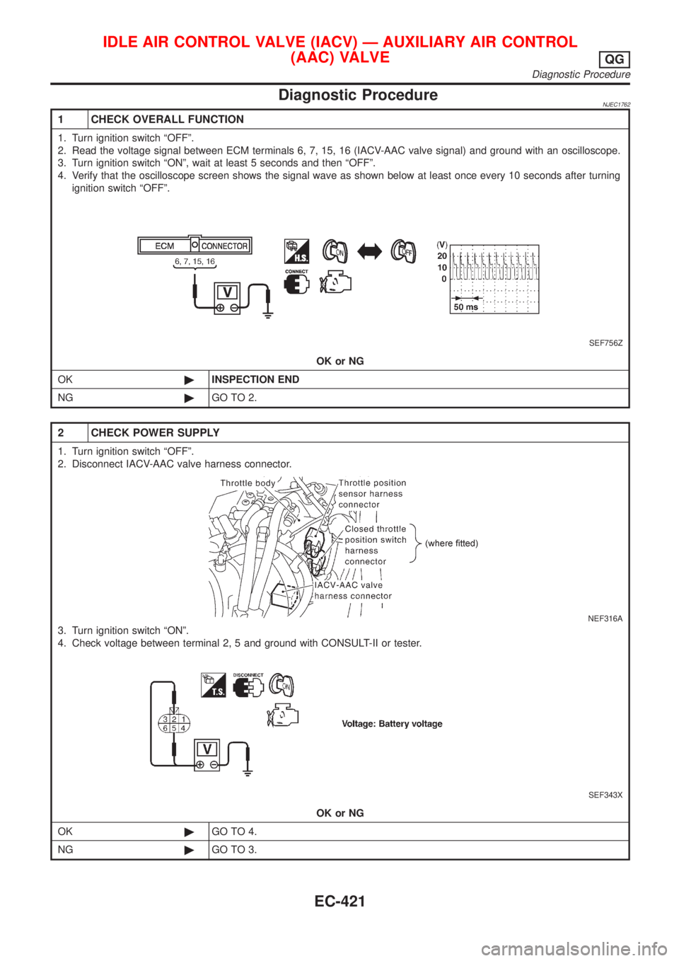
2. Read the voltage signal between ECM terminals 6, 7, 15, 16 (IACV-AAC valve signal) and ground with an oscilloscope.
3. Turn ignition switch ªONº, wait at least 5 seconds and then ªOFFº.
4. Verify that the oscilloscope screen shows the signal wave as shown below at least once every 10 seconds after turning
ignition switch ªOFFº.
SEF756Z
OK or NG
OK©INSPECTION END
NG©GO TO 2.
2 CHECK POWER SUPPLY
1. Turn ignition switch ªOFFº.
2. Disconnect IACV-AAC valve harness connector.
NEF316A
3. Turn ignition switch ªONº.
4. Check voltage between terminal 2, 5 and ground with CONSULT-II or tester.
SEF343X
OK or NG
OK©GO TO 4.
NG©GO TO 3.
IDLE AIR CONTROL VALVE (IACV) Ð AUXILIARY AIR CONTROL
(AAC) VALVE
QG
Diagnostic Procedure
EC-421
Page 718 of 2493
3 DETECT MALFUNCTIONING PART
Check the following.
+15A fuse
+Harness connectors E75, F36 (If so equipped)
+Harness for open or short between fuse and ECM relay
+ECM relay
+Harness for open or short between IACV-AAC and ECM relay.
©Repair harness or connectors, or replace fuse or ECM relay.
4 CHECK OUTPUT SIGNAL CIRCUIT
1. Turn ignition switch ªOFFº.
2. Disconnect ECM harness connector.
3. Check harness continuity between
ECM terminal 6 and IACV-AAC valve terminal 1,
ECM terminal 7 and IACV-AAC valve terminal 4,
ECM terminal 15 and IACV-AAC valve terminal 3,
ECM terminal 16 and IACV-AAC valve terminal 6.
Refer to wiring diagram.
Continuity should exist.
4. Also check harness for short to ground and short to power.
OK or NG
OK©GO TO 5.
NG©Repair open circuit or short to ground or short to power in harness or connectors.
5 CHECK AIR CONTROL VALVE (POWER STEERING) OPERATION-I
1. Reconnect the ECM harness connector and IACV-AAC valve harness connector.
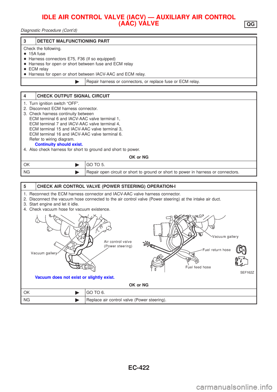
2. Disconnect the vacuum hose connected to the air control valve (Power steering) at the intake air duct.
3. Start engine and let it idle.
4. Check vacuum hose for vacuum existence.
SEF162Z
Vacuum does not exist or slightly exist.
OK or NG
OK©GO TO 6.
NG©Replace air control valve (Power steering).
IDLE AIR CONTROL VALVE (IACV) Ð AUXILIARY AIR CONTROL
(AAC) VALVE
QG
Diagnostic Procedure (Cont'd)
EC-422
Page 719 of 2493
6 CHECK AIR CONTROL VALVE (POWER STEERING) OPERATION-II
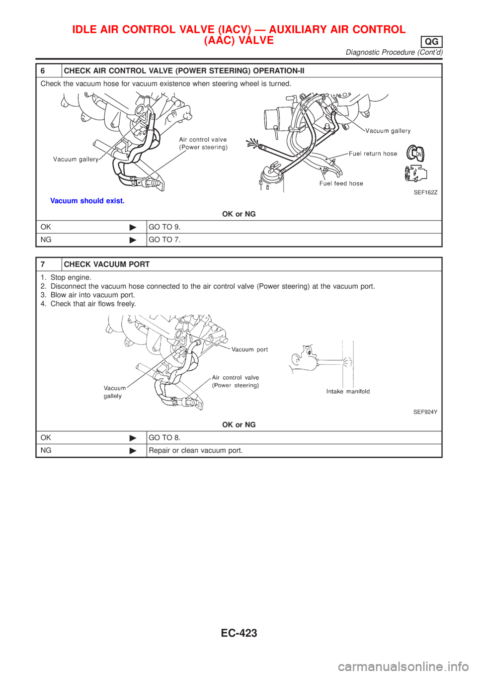
Check the vacuum hose for vacuum existence when steering wheel is turned.
SEF162Z
Vacuum should exist.
OK or NG
OK©GO TO 9.
NG©GO TO 7.
7 CHECK VACUUM PORT
1. Stop engine.
2. Disconnect the vacuum hose connected to the air control valve (Power steering) at the vacuum port.
3. Blow air into vacuum port.
4. Check that air flows freely.
SEF924Y
OK or NG
OK©GO TO 8.
NG©Repair or clean vacuum port.
IDLE AIR CONTROL VALVE (IACV) Ð AUXILIARY AIR CONTROL
(AAC) VALVE
QG
Diagnostic Procedure (Cont'd)
EC-423
Page 720 of 2493
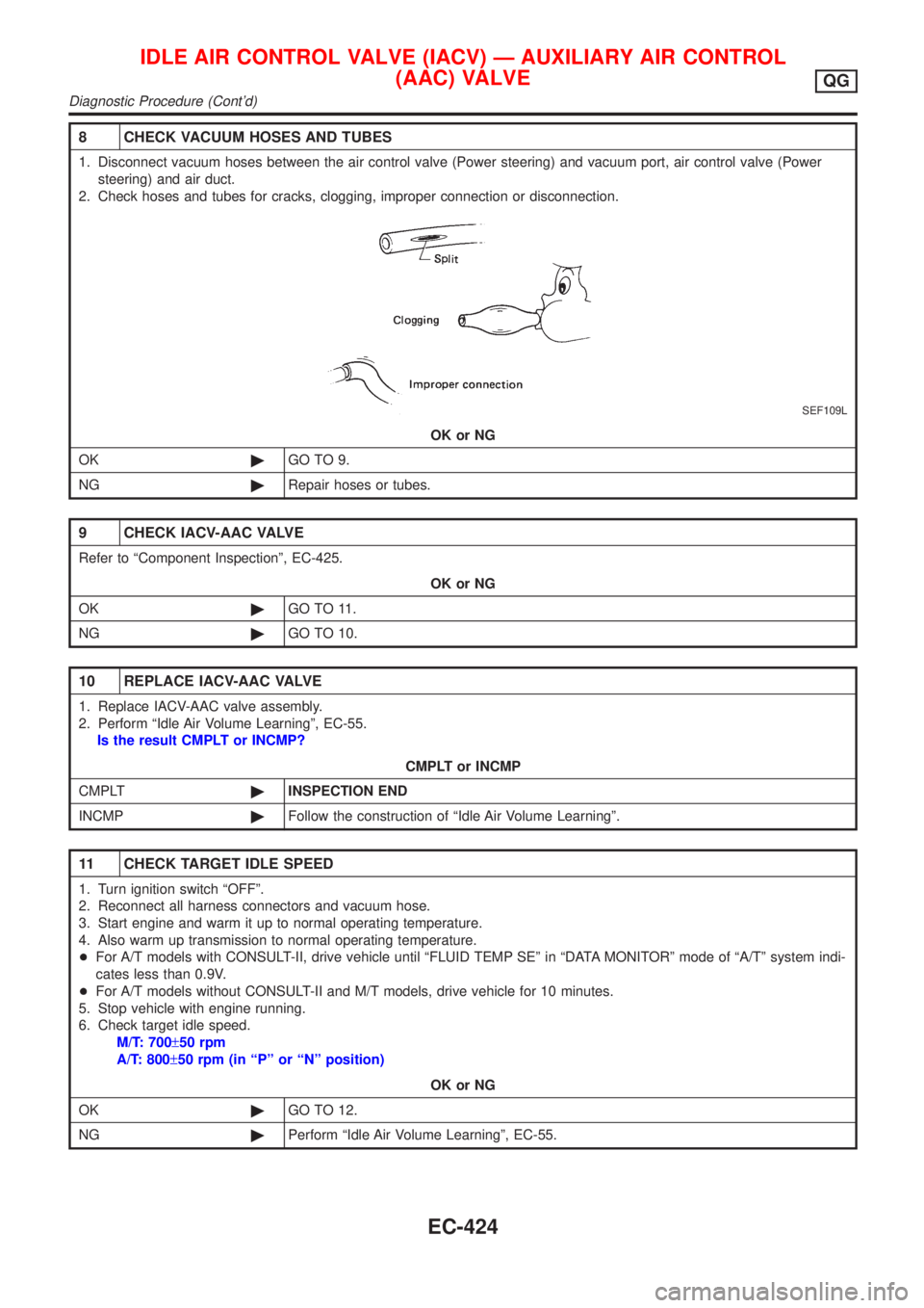
8 CHECK VACUUM HOSES AND TUBES
1. Disconnect vacuum hoses between the air control valve (Power steering) and vacuum port, air control valve (Power
steering) and air duct.
2. Check hoses and tubes for cracks, clogging, improper connection or disconnection.
SEF109L
OK or NG
OK©GO TO 9.
NG©Repair hoses or tubes.
9 CHECK IACV-AAC VALVE
Refer to ªComponent Inspectionº, EC-425.
OK or NG
OK©GO TO 11.
NG©GO TO 10.
10 REPLACE IACV-AAC VALVE
1. Replace IACV-AAC valve assembly.
2. Perform ªIdle Air Volume Learningº, EC-55.
Is the result CMPLT or INCMP?
CMPLT or INCMP
CMPLT©INSPECTION END
INCMP©Follow the construction of ªIdle Air Volume Learningº.
11 CHECK TARGET IDLE SPEED
1. Turn ignition switch ªOFFº.
2. Reconnect all harness connectors and vacuum hose.
3. Start engine and warm it up to normal operating temperature.
4. Also warm up transmission to normal operating temperature.
+For A/T models with CONSULT-II, drive vehicle until ªFLUID TEMP SEº in ªDATA MONITORº mode of ªA/Tº system indi-
cates less than 0.9V.
+For A/T models without CONSULT-II and M/T models, drive vehicle for 10 minutes.
5. Stop vehicle with engine running.
6. Check target idle speed.
M/T: 700±50 rpm
A/T: 800±50 rpm (in ªPº or ªNº position)
OK or NG
OK©GO TO 12.
NG©Perform ªIdle Air Volume Learningº, EC-55.
IDLE AIR CONTROL VALVE (IACV) Ð AUXILIARY AIR CONTROL
(AAC) VALVE
QG
Diagnostic Procedure (Cont'd)
EC-424
Page 721 of 2493
12 CHECK INTERMITTENT INCIDENT
Perform ªTROUBLE DIAGNOSIS FOR INTERMITTENT INCIDENTº, EC-144.
©INSPECTION END
SEF605Y
SEF089X
Component InspectionNJEC1763IACV-AAC VALVENJEC1763S011) Disconnect IACV-AAC valve harness connector.
2) Check IACV-AAC valve resistance.
Condition Resistance
Terminal 2 and terminals 1, 3
20-24W[at 20ÉC (68ÉF)]
Terminal 5 and terminals 4, 6
3) Reconnect IACV-AAC valve harness connector.
4) Remove idle air adjusting unit assembly (IACV-AAC valve is
built-in) from engine.
(The IACV-AAC valve harness connector should remain con-
nected.)
5) Turn ignition switch ªONº and ªOFFº, and ensure the IACV-
AAC valve shaft smoothly moves forward and backward,
according to the ignition switch position.
If NG, replace the IACV-AAC valve.
IDLE AIR CONTROL VALVE (IACV) Ð AUXILIARY AIR CONTROL
(AAC) VALVE
QG
Diagnostic Procedure (Cont'd)
EC-425
Page 1216 of 2493
TCM FUNCTION=NJAT0014S03The function of the TCM is to:
+Receive input signals sent from various switches and sensors.
+Determine required line pressure, shifting point, lock-up operation, and engine brake operation.
+Send required output signals to the respective solenoids.
INPUT/OUTPUT SIGNAL OF TCMNJAT0014S04
Sensors, switches and solenoid
valvesFunction
InputPNP switch Detects select lever position and sends a signal to TCM.
Throttle position sensor Detects throttle valve position and sends a signal to TCM.
Closed throttle position switch Detects throttle valve's fully-closed position and sends a signal to TCM.
Wide open throttle position switchDetects a throttle valve position of greater than 1/2 of full throttle and sends
a signal to TCM.
Engine speed signal From ECM.
A/T fluid temperature sensor Detects transmission fluid temperature and sends a signal to TCM.
Revolution sensor Detects output shaft rpm and sends a signal to TCM.
Vehicle speed sensorUsed as an auxiliary vehicle speed sensor. Sends a signal when revolution
sensor (installed on transmission) malfunctions.
Overdrive control switchSends a signal, which prohibits a shift to ªD
4º (overdrive) position, to the
TCM.
Stop lamp switch Releases lock-up system when depressing pedal in lock-up condition.
OutputShift solenoid valve A/BSelects shifting point suited to driving conditions in relation to a signal sent
from TCM.
Line pressure solenoid valveRegulates (or decreases) line pressure suited to driving conditions in rela-
tion to a signal sent from TCM.
Torque converter clutch solenoid
valveRegulates (or decreases) lock-up pressure suited to driving conditions in
relation to a signal sent from TCM.
Overrun clutch solenoid valveControls an ªengine brakeº effect suited to driving conditions in relation to a
signal sent from TCM.
O/D OFF indicator lamp Shows TCM faults, when A/T control components malfunction.
Control MechanismNJAT0015LINE PRESSURE CONTROLNJAT0015S01TCM has various line pressure control characteristics to match the
driving conditions.
An ON-OFF duty signal is sent to the line pressure solenoid valve
based on TCM characteristics.
Hydraulic pressure on the clutch and brake is electronically con-
trolled through the line pressure solenoid valve to accommodate
engine torque. This results in smooth shift operation.
OVERALL SYSTEM
Control System (Cont'd)
AT-30
Page 1315 of 2493
SAT059K
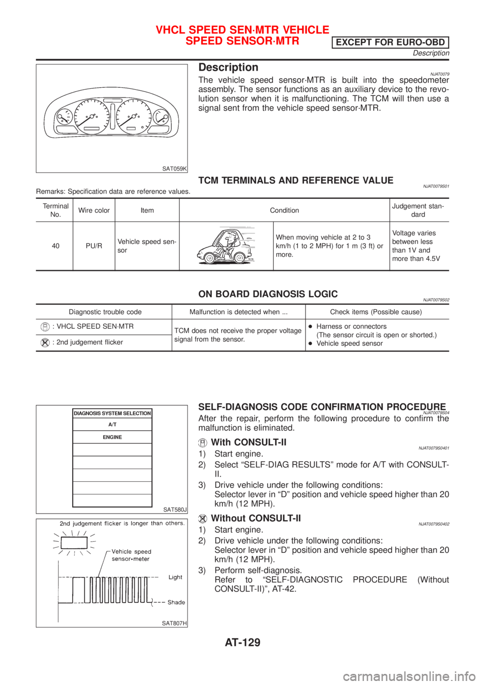
DescriptionNJAT0079The vehicle speed sensor´MTR is built into the speedometer
assembly. The sensor functions as an auxiliary device to the revo-
lution sensor when it is malfunctioning. The TCM will then use a
signal sent from the vehicle speed sensor´MTR.
TCM TERMINALS AND REFERENCE VALUENJAT0079S01Remarks: Specification data are reference values.
Terminal
No.Wire color Item ConditionJudgement stan-
dard
40 PU/RVehicle speed sen-
sor
When moving vehicle at 2 to 3
km/h (1 to 2 MPH) for1m(3ft)or
more.Voltage varies
between less
than 1V and
more than 4.5V
ON BOARD DIAGNOSIS LOGICNJAT0079S02
Diagnostic trouble code Malfunction is detected when ... Check items (Possible cause)
: VHCL SPEED SEN´MTR
TCM does not receive the proper voltage
signal from the sensor.+Harness or connectors
(The sensor circuit is open or shorted.)
+Vehicle speed sensor
: 2nd judgement flicker
SAT580J
SAT807H
SELF-DIAGNOSIS CODE CONFIRMATION PROCEDURENJAT0079S04After the repair, perform the following procedure to confirm the
malfunction is eliminated.
With CONSULT-IINJAT0079S04011) Start engine.
2) Select ªSELF-DIAG RESULTSº mode for A/T with CONSULT-
II.
3) Drive vehicle under the following conditions:
Selector lever in ªDº position and vehicle speed higher than 20
km/h (12 MPH).
Without CONSULT-IINJAT0079S04021) Start engine.
2) Drive vehicle under the following conditions:
Selector lever in ªDº position and vehicle speed higher than 20
km/h (12 MPH).
3) Perform self-diagnosis.
Refer to ªSELF-DIAGNOSTIC PROCEDURE (Without
CONSULT-II)º, AT-42.
VHCL SPEED SEN´MTR VEHICLE
SPEED SENSOR´MTR
EXCEPT FOR EURO-OBD
Description
AT-129