2001 NISSAN ALMERA N16 wiring diagram
[x] Cancel search: wiring diagramPage 990 of 2493
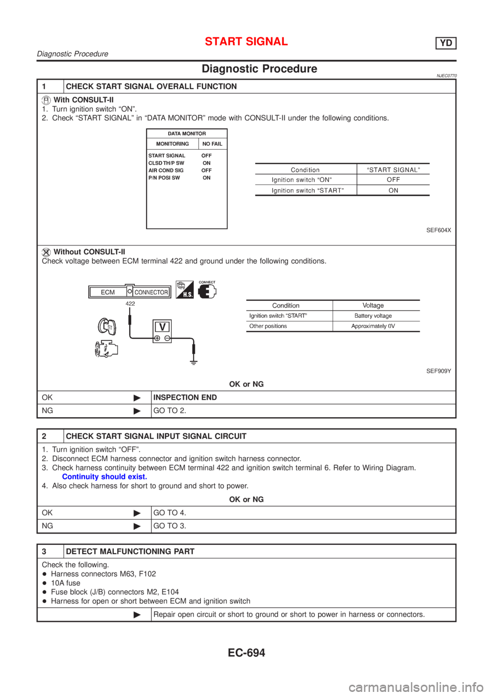
Diagnostic ProcedureNJEC0770
1 CHECK START SIGNAL OVERALL FUNCTION
With CONSULT-II
1. Turn ignition switch ªONº.
2. Check ªSTART SIGNALº in ªDATA MONITORº mode with CONSULT-II under the following conditions.
SEF604X
Without CONSULT-II
Check voltage between ECM terminal 422 and ground under the following conditions.
SEF909Y
OK or NG
OK©INSPECTION END
NG©GO TO 2.
2 CHECK START SIGNAL INPUT SIGNAL CIRCUIT
1. Turn ignition switch ªOFFº.
2. Disconnect ECM harness connector and ignition switch harness connector.
3. Check harness continuity between ECM terminal 422 and ignition switch terminal 6. Refer to Wiring Diagram.
Continuity should exist.
4. Also check harness for short to ground and short to power.
OK or NG
OK©GO TO 4.
NG©GO TO 3.
3 DETECT MALFUNCTIONING PART
Check the following.
+Harness connectors M63, F102
+10A fuse
+Fuse block (J/B) connectors M2, E104
+Harness for open or short between ECM and ignition switch
©Repair open circuit or short to ground or short to power in harness or connectors.
START SIGNALYD
Diagnostic Procedure
EC-694
Page 993 of 2493
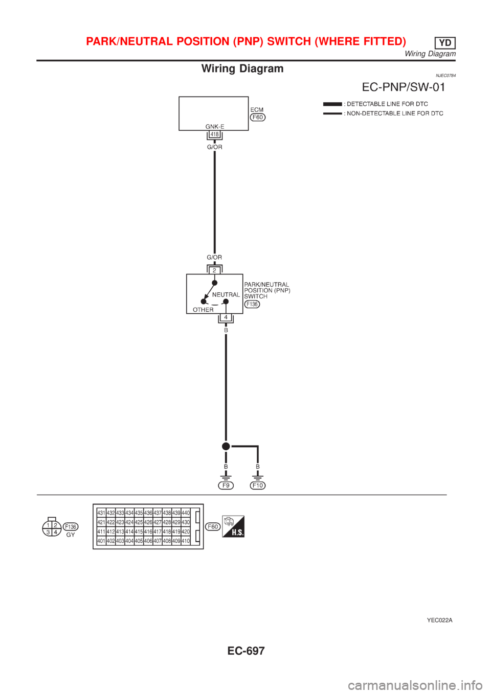
Wiring DiagramNJEC0784
YEC022A
PARK/NEUTRAL POSITION (PNP) SWITCH (WHERE FITTED)YD
Wiring Diagram
EC-697
Page 995 of 2493
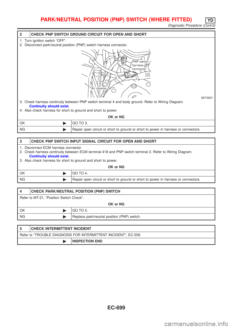
2 CHECK PNP SWITCH GROUND CIRCUIT FOR OPEN AND SHORT
1. Turn ignition switch ªOFFº.
2. Disconnect park/neutral position (PNP) switch harness connector.
SEF393Y
3. Check harness continuity between PNP switch terminal 4 and body ground. Refer to Wiring Diagram.
Continuity should exist.
4. Also check harness for short to ground and short to power.
OK or NG
OK©GO TO 3.
NG©Repair open circuit or short to ground or short to power in harness or connectors.
3 CHECK PNP SWITCH INPUT SIGNAL CIRCUIT FOR OPEN AND SHORT
1. Disconnect ECM harness connector.
2. Check harness continuity between ECM terminal 418 and PNP switch terminal 2. Refer to Wiring Diagram.
Continuity should exist.
3. Also check harness for short to ground and short to power.
OK or NG
OK©GO TO 4.
NG©Repair open circuit or short to ground or short to power in harness or connectors.
4 CHECK PARK/NEUTRAL POSITION (PNP) SWITCH
Refer to MT-21, ªPosition Switch Checkº.
OK or NG
OK©GO TO 5.
NG©Replace park/neutral position (PNP) switch.
5 CHECK INTERMITTENT INCIDENT
Refer to ªTROUBLE DIAGNOSIS FOR INTERMITTENT INCIDENTº, EC-559.
©INSPECTION END
PARK/NEUTRAL POSITION (PNP) SWITCH (WHERE FITTED)YD
Diagnostic Procedure (Cont'd)
EC-699
Page 996 of 2493
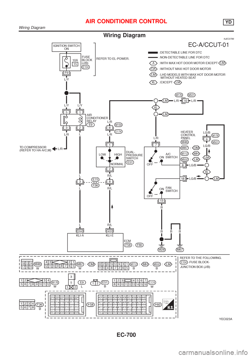
Wiring DiagramNJEC0786
YEC023A
AIR CONDITIONER CONTROLYD
Wiring Diagram
EC-700
Page 997 of 2493
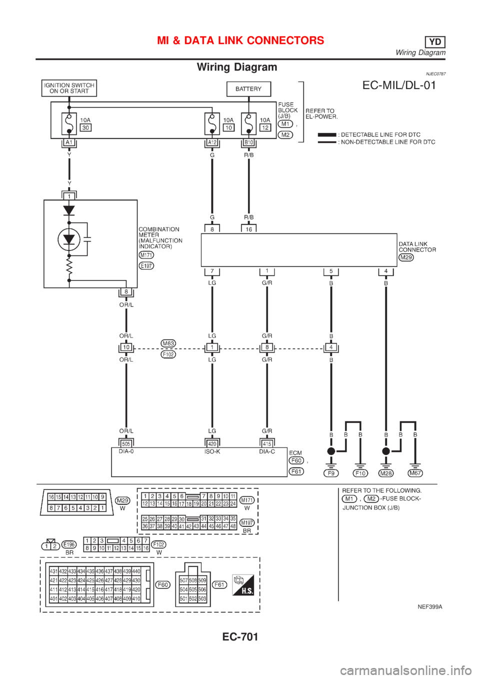
Wiring DiagramNJEC0787
NEF399A
MI & DATA LINK CONNECTORSYD
Wiring Diagram
EC-701
Page 1187 of 2493
AUTOMATIC TRANSAXLE
SECTION
AT
CONTENTS
EURO-OBD
TROUBLE DIAGNOSIS - INDEX....................................5
Alphabetical & P No. Index for DTC ...........................5
PRECAUTIONS...............................................................7
Supplemental Restraint System (SRS)²AIR
BAG²and²SEAT BELT PRE-TENSIONER²...............7
Precautions for On Board Diagnostic (EURO-
OBD) System of A/T and Engine - Euro-OBD - ..........7
Precautions ..................................................................7
Service Notice or Precautions .....................................9
Wiring Diagrams and Trouble Diagnosis ...................10
PREPARATION............................................................. 11
Special Service Tools ................................................ 11
Commercial Service Tools .........................................13
A/T FLUID......................................................................15
Checking A/T Fluid ....................................................15
Changing A/T Fluid ....................................................15
OVERALL SYSTEM......................................................16
A/T Electrical Parts Location .....................................16
Circuit Diagram ..........................................................17
Cross-sectional View - ...............................................18
Hydraulic Control Circuit ............................................19
Shift Mechanism ........................................................20
Control System ..........................................................29
Control Mechanism ....................................................30
Control Valve .............................................................35
EXCEPT FOR EURO-OBD
ON BOARD DIAGNOSTIC SYSTEM............................37
CONSULT-II ...............................................................37
Diagnostic Procedure Without CONSULT-II ..............42
EURO-OBD
ON BOARD DIAGNOSTIC SYSTEM
DESCRIPTION...............................................................48Introduction ................................................................48
EURO-OBD Function for A/T System .......................48
One or Two Trip Detection Logic of EURO-OBD ......48
EURO-OBD Diagnostic Trouble Code (DTC)............48
Malfunction Indicator (MI) ..........................................52
CONSULT-II ...............................................................52
Diagnostic Procedure Without CONSULT-II ..............61
EXCEPT FOR EURO-OBD
TROUBLE DIAGNOSIS -...............................................67
Introduction ................................................................67
Work Flow ..................................................................71
EURO-OBD
TROUBLE DIAGNOSIS - INTRODUCTION..................72
Introduction ................................................................72
Work Flow ..................................................................76
TROUBLE DIAGNOSIS - BASIC INSPECTION...........78
A/T Fluid Check .........................................................78
Stall Test ....................................................................78
Line Pressure Test .....................................................82
Road Test...................................................................83
TROUBLE DIAGNOSIS - GENERAL
DESCRIPTION.............................................................103
Symptom Chart ........................................................103
TCM Terminals and Reference Value...................... 116
TROUBLE DIAGNOSIS FOR POWER SUPPLY........121
Wiring Diagram - AT - MAIN ....................................121
Diagnostic Procedure ..............................................122
EXCEPT FOR EURO-OBD
VEHICLE SPEED SENSOR.A/T..................................124
Description ...............................................................124
Wiring Diagram - AT - VSSA/T ................................126
Diagnostic Procedure ..............................................127
Page 1188 of 2493
VHCL SPEED SEN.MTR VEHICLE............................129
Description ...............................................................129
Wiring Diagram - AT - VSSMTR ..............................130
Diagnostic Procedure ..............................................131
THROTTLE POSITION................................................132
Description ...............................................................132
Wiring Diagram - AT - TPS ......................................134
Diagnostic Procedure ..............................................135
Component Inspection .............................................139
SHIFT SOLENOID VALVE A......................................140
Description ...............................................................140
Wiring Diagram - AT - SSV/A ..................................142
Diagnostic Procedure ..............................................143
Component Inspection .............................................145
SHIFT SOLENOID VALVE B......................................146
Description ...............................................................146
Wiring Diagram - AT - SSV/B ..................................148
Diagnostic Procedure ..............................................149
Component Inspection .............................................151
OVERRUN CLUTCH SOLENOID................................152
Description ...............................................................152
Wiring Diagram - AT - OVRCSV..............................153
Diagnostic Procedure ..............................................154
Component Inspection .............................................156
TORQUE CONVERTER CLUTCH...............................157
Description ...............................................................157
Wiring Diagram - AT - TCV......................................159
Diagnostic Procedure ..............................................160
Component Inspection .............................................162
BATT/FLUID TEMP SEN (A/T FLUID TEMP
SENSOR CIRCUIT AND TCM POWER SOURCE)....163
Description ...............................................................163
Wiring Diagram - AT - BA/FTS ................................165
Diagnostic Procedure ..............................................166
Component Inspection .............................................169
ENGINE SPEED SIGNAL............................................170
Description ...............................................................170
Wiring Diagram - AT - ENGSS ................................171
Diagnostic Procedure ..............................................172
LINE PRESSURE SOLENOID....................................174
Description ...............................................................174
Wiring Diagram - AT - LPSV....................................176
Diagnostic Procedure ..............................................177
Component Inspection .............................................180
EURO-OBD
DTC P0705 PARK/NEUTRAL POSITION (PNP)
SWITCH.......................................................................181
Description ...............................................................181
Wiring Diagram - AT - PNP/SW...............................183
Diagnostic Procedure ..............................................184
Component Inspection .............................................186DTC P0710 A/T FLUID TEMPERATURE SENSOR
CIRCUIT.......................................................................187
Description ...............................................................187
Wiring Diagram - AT - FTS ......................................189
Diagnostic Procedure ..............................................190
Component Inspection .............................................192
DTC P0720 VEHICLE SPEED SENSOR.A/T..............193
Description ...............................................................193
Wiring Diagram - AT - VSSA/T ................................195
Diagnostic Procedure ..............................................196
DTC P0725 ENGINE SPEED SIGNAL.......................198
Description ...............................................................198
Wiring Diagram - AT - ENGSS ................................199
Diagnostic Procedure ..............................................200
DTC P0731 A/T 1ST GEAR FUNCTION....................202
Description ...............................................................202
Wiring Diagram - AT - 1ST ......................................205
Diagnostic Procedure ..............................................206
Component Inspection .............................................207
DTC P0732 A/T 2ND GEAR FUNCTION....................209
Description ...............................................................209
Wiring Diagram - AT - 2ND......................................212
Diagnostic Procedure ..............................................213
Component Inspection .............................................214
DTC P0733 A/T 3RD GEAR FUNCTION....................215
Description ...............................................................215
Wiring Diagram - AT - 3RD......................................218
Diagnostic Procedure ..............................................219
Component Inspection .............................................220
DTC P0734 A/T 4TH GEAR FUNCTION....................221
Description ...............................................................221
Wiring Diagram - AT - 4TH ......................................225
Diagnostic Procedure ..............................................226
Component Inspection .............................................230
DTC P0740 TORQUE CONVERTER CLUTCH..........231
Description ...............................................................231
Wiring Diagram - AT - TCV......................................233
Diagnostic Procedure ..............................................234
Component Inspection .............................................236
DTC P0745 LINE PRESSURE SOLENOID VALVE...237
Description ...............................................................237
Wiring Diagram - AT - LPSV....................................239
Diagnostic Procedure ..............................................240
Component Inspection .............................................243
DTC P0750 SHIFT SOLENOID VALVE A..................244
Description ...............................................................244
Wiring Diagram - AT - SSV/A ..................................246
Diagnostic Procedure ..............................................247
Component Inspection .............................................249
DTC P0755 SHIFT SOLENOID VALVE B..................250
Description ...............................................................250
Wiring Diagram - AT - SSV/B ..................................252
CONTENTS(Cont'd)
AT-2
Page 1189 of 2493
Diagnostic Procedure ..............................................253
Component Inspection .............................................255
DTC P1705 THROTTLE POSITION SENSOR...........256
Description ...............................................................256
Wiring Diagram - AT - TPS ......................................259
Diagnostic Procedure ..............................................260
Component Inspection .............................................264
DTC P1760 OVERRUN CLUTCH SOLENOID
VALVE..........................................................................265
Description ...............................................................265
Wiring Diagram - AT - OVRCSV..............................267
Diagnostic Procedure ..............................................268
Component Inspection .............................................270
DTC BATT/FLUID TEMP SEN (A/T FLUID TEMP
SENSOR CIRCUIT AND TCM POWER SOURCE)....271
Description ...............................................................271
Wiring Diagram - AT - BA/FTS ................................273
Diagnostic Procedure ..............................................274
Component Inspection .............................................277
DTC VHCL SPEED SEN.MTR VEHICLE SPEED......278
Description ...............................................................278
Wiring Diagram - AT - VSSMTR ..............................280
Diagnostic Procedure ..............................................281
DTC CONTROL UNIT (RAM), CONTROL UNIT
(ROM)...........................................................................282
Description ...............................................................282
Diagnostic Procedure ..............................................282
DTC CONTROL UNIT (EEP ROM).............................284
Description ...............................................................284
Diagnostic Procedure ..............................................285
TROUBLE DIAGNOSES FOR SYMPTOMS...............286
Wiring Diagram - AT - NONDTC .............................286
1. O/D OFF Indicator Lamp Does Not Come On....288
2. Engine Cannot Be Started In²P²and²N²
Position ....................................................................291
3. In²P²Position, Vehicle Moves Forward Or
Backward When Pushed .........................................292
4. In²N²Position, Vehicle Moves ...........................293
5. Large Shock.²N²->²R²Position .......................295
6. Vehicle Does Not Creep Backward In²R²
Position ....................................................................297
7. Vehicle Does Not Creep Forward In²D²,²2²
Or²1²Position .........................................................300
8. Vehicle Cannot Be Started From D
1...................303
9. A/T Does Not Shift: D
1-> D2Or Does Not
Kickdown: D
4-> D2..................................................306
10. A/T Does Not Shift: D
2-> D3.............................309
11. A/T Does Not Shift: D
3-> D4.............................312
12. A/T Does Not Perform Lock-up .........................315
13. A/T Does Not Hold Lock-up Condition ..............31714. Lock-up Is Not Released ...................................319
15. Engine Speed Does Not Return To Idle (Light
Braking D
4-> D3).....................................................320
16. Vehicle Does Not Start From D
1.......................322
17. A/T Does Not Shift: D
4-> D3, When
Overdrive Control Switch²ON²->²OFF²...............323
18. A/T Does Not Shift: D
3-> 22, When Selector
Lever²D²->²2²Position.........................................324
19. A/T Does Not Shift: 2
2-> 11, When Selector
Lever²2²->²1²Position .........................................325
20. Vehicle Does Not Decelerate By Engine
Brake........................................................................326
21. TCM Self-diagnosis Does Not Activate (PNP,
Overdrive Control and Throttle Position Switches
Circuit Checks) ........................................................326
A/T SHIFT LOCK SYSTEM.........................................335
Description ...............................................................335
Shift Lock System Electrical Parts Location............335
Wiring Diagram - SHIFT -........................................336
Diagnostic Procedure ..............................................337
KEY INTERLOCK CABLE..........................................341
Components.............................................................341
Removal ...................................................................341
Installation ................................................................342
ON-VEHICLE SERVICE..............................................343
Control Valve Assembly and Accumulators .............343
Control Cable Adjustment ........................................344
Park/Neutral Position (PNP) Switch Adjustment .....344
Differential Side Oil Seal Replacement ...................345
Revolution Sensor Replacement .............................345
REMOVAL AND INSTALLATION...............................346
Removal ...................................................................346
Installation ................................................................347
OVERHAUL.................................................................349
Components-1 .........................................................349
Components-2 .........................................................350
Components-3 .........................................................351
Oil Channel ..............................................................352
Locations of Adjusting Shims, Needle Bearings,
Thrust Washers and Snap Rings ............................353
DISASSEMBLY............................................................354
REPAIR FOR COMPONENT PARTS.........................368
Manual Shaft............................................................368
Oil Pump ..................................................................371
Control Valve Assembly ...........................................375
Control Valve Upper Body .......................................384
Control Valve Lower Body .......................................388
Reverse Clutch ........................................................390
High Clutch ..............................................................394
Forward Clutch and Overrun Clutch........................399
Low & Reverse Brake..............................................406
CONTENTS(Cont'd)
AT-3