2001 NISSAN ALMERA N16 belt
[x] Cancel search: beltPage 1893 of 2493
FOR SIDE COLLISION=NJRS0033S08To repair the SRS for a side collision, perform the following steps.
When the side air bag is activated in a side collision:
1) Replace the following component:
þ All parts of front seatback (including front seatback frame) with side air bag module (on the side on which
side air bag is activated)
þ Diagnosis sensor unit
þ Side air bag (satellite) sensor (on the side on which side air bag is activated)
2) Check the SRS components and the related parts using the table shown below.
+Replace any SRS components and the related parts showing visible signs of damage (dents, cracks,
deformation).
3) Conduct self-diagnosis using CONSULT-II or ªAIR BAGº warning lamp. Refer to ªSRS Operation Checkº
for details (RS-49). Ensure entire SRS operation properly.
When SRS is not activated in the side collision:
1) Check the SRS components and the related parts using the table shown below.
+Replace any SRS components and the related parts showing visible signs of damage (dents, cracks,
deformation).
2) Conduct self-diagnosis using CONSULT-II or ªAIR BAGº warning lamp. Refer to ªSRS Operation Checkº
for details (RS-49). Ensure entire SRS operation properly.
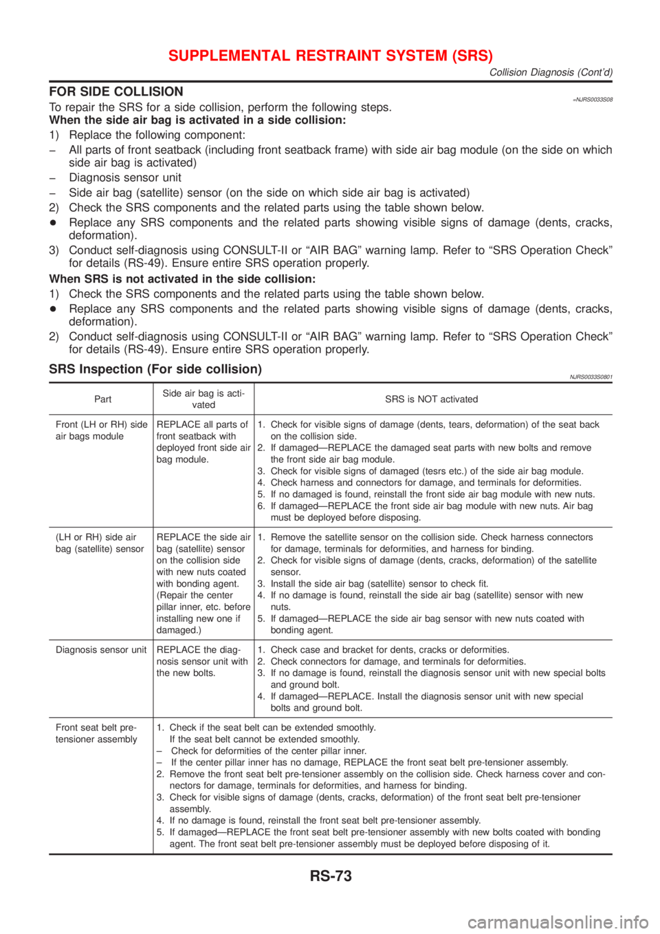
SRS Inspection (For side collision)NJRS0033S0801
PartSide air bag is acti-
vatedSRS is NOT activated
Front (LH or RH) side
air bags moduleREPLACE all parts of
front seatback with
deployed front side air
bag module.1. Check for visible signs of damage (dents, tears, deformation) of the seat back
on the collision side.
2. If damagedÐREPLACE the damaged seat parts with new bolts and remove
the front side air bag module.
3. Check for visible signs of damaged (tesrs etc.) of the side air bag module.
4. Check harness and connectors for damage, and terminals for deformities.
5. If no damaged is found, reinstall the front side air bag module with new nuts.
6. If damagedÐREPLACE the front side air bag module with new nuts. Air bag
must be deployed before disposing.
(LH or RH) side air
bag (satellite) sensorREPLACE the side air
bag (satellite) sensor
on the collision side
with new nuts coated
with bonding agent.
(Repair the center
pillar inner, etc. before
installing new one if
damaged.)1. Remove the satellite sensor on the collision side. Check harness connectors
for damage, terminals for deformities, and harness for binding.
2. Check for visible signs of damage (dents, cracks, deformation) of the satellite
sensor.
3. Install the side air bag (satellite) sensor to check fit.
4. If no damage is found, reinstall the side air bag (satellite) sensor with new
nuts.
5. If damagedÐREPLACE the side air bag sensor with new nuts coated with
bonding agent.
Diagnosis sensor unit REPLACE the diag-
nosis sensor unit with
the new bolts.1. Check case and bracket for dents, cracks or deformities.
2. Check connectors for damage, and terminals for deformities.
3. If no damage is found, reinstall the diagnosis sensor unit with new special bolts
and ground bolt.
4. If damagedÐREPLACE. Install the diagnosis sensor unit with new special
bolts and ground bolt.
Front seat belt pre-
tensioner assembly1. Check if the seat belt can be extended smoothly.
If the seat belt cannot be extended smoothly.
± Check for deformities of the center pillar inner.
± If the center pillar inner has no damage, REPLACE the front seat belt pre-tensioner assembly.
2. Remove the front seat belt pre-tensioner assembly on the collision side. Check harness cover and con-
nectors for damage, terminals for deformities, and harness for binding.
3. Check for visible signs of damage (dents, cracks, deformation) of the front seat belt pre-tensioner
assembly.
4. If no damage is found, reinstall the front seat belt pre-tensioner assembly.
5. If damagedÐREPLACE the front seat belt pre-tensioner assembly with new bolts coated with bonding
agent. The front seat belt pre-tensioner assembly must be deployed before disposing of it.
SUPPLEMENTAL RESTRAINT SYSTEM (SRS)
Collision Diagnosis (Cont'd)
RS-73
Page 1895 of 2493
BODY & TRIM
SECTION
BT
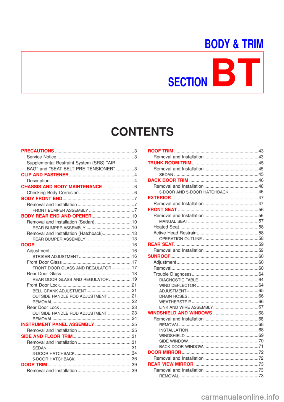
CONTENTS
PRECAUTIONS...............................................................3
Service Notice..............................................................3
Supplemental Restraint System (SRS)²AIR
BAG²and²SEAT BELT PRE-TENSIONER²...............3
CLIP AND FASTENER....................................................4
Description ...................................................................4
CHASSIS AND BODY MAINTENANCE.........................6
Checking Body Corrosion ............................................6
BODY FRONT END.........................................................7
Removal and Installation .............................................7
FRONT BUMPER ASSEMBLY....................................7
BODY REAR END AND OPENER................................10
Removal and Installation (Sedan) .............................10
REAR BUMPER ASSEMBLY....................................10
Removal and Installation (Hatchback).......................13
REAR BUMPER ASSEMBLY....................................13
DOOR.............................................................................16
Adjustment .................................................................16
STRIKER ADJUSTMENT..........................................16
Front Door Glass .......................................................17
FRONT DOOR GLASS AND REGULATOR................17
Rear Door Glass ........................................................18
REAR DOOR GLASS AND REGULATOR..................19
Front Door Lock .........................................................21
BELL CRANK ADJUSTMENT....................................21
OUTSIDE HANDLE ROD ADJUSTMENT...................21
REMOVAL...............................................................22
Rear Door Lock .........................................................23
OUTSIDE HANDLE ROD ADJUSTMENT...................23
REMOVAL...............................................................24
INSTRUMENT PANEL ASSEMBLY.............................25
Removal and Installation ...........................................25
SIDE AND FLOOR TRIM...............................................31
Removal and Installation ...........................................31
SEDAN...................................................................31
3-DOOR HATCHBACK.............................................34
5-DOOR HATCHBACK.............................................36
DOOR TRIM...................................................................39
Removal and Installation ...........................................39ROOF TRIM...................................................................43
Removal and Installation ...........................................43
TRUNK ROOM TRIM.....................................................45
Removal and Installation ...........................................45
SEDAN...................................................................45
BACK DOOR TRIM.......................................................46
Removal and Installation ...........................................46
3-DOOR AND 5-DOOR HATCHBACK.......................46
EXTERIOR.....................................................................47
Removal and Installation ...........................................47
FRONT SEAT................................................................56
Removal and Installation ...........................................56
MANUAL SEAT........................................................57
Heated Seat ...............................................................58
Active Head Restraint ................................................58
OPERATION OUTLINE............................................58
REAR SEAT...................................................................59
Removal and Installation ...........................................59
SUNROOF......................................................................60
Adjustment .................................................................60
Removal .....................................................................60
Trouble Diagnoses.....................................................64
DIAGNOSTIC TABLE................................................64
WIND DEFLECTOR.................................................64
ADJUSTMENT.........................................................65
DRAIN HOSES........................................................66
WEATHERSTRIP.....................................................66
LINK AND WIRE ASSEMBLY....................................67
WINDSHIELD AND WINDOWS....................................68
Removal and Installation ...........................................68
REMOVAL...............................................................68
INSTALLATION........................................................68
WINDSHIELD..........................................................69
SIDE WINDOW........................................................70
BACK DOOR WINDOW............................................71
DOOR MIRROR.............................................................72
Removal and Installation ...........................................72
REAR VIEW MIRROR...................................................73
Removal and Installation ...........................................73
REMOVAL...............................................................73
Page 1897 of 2493
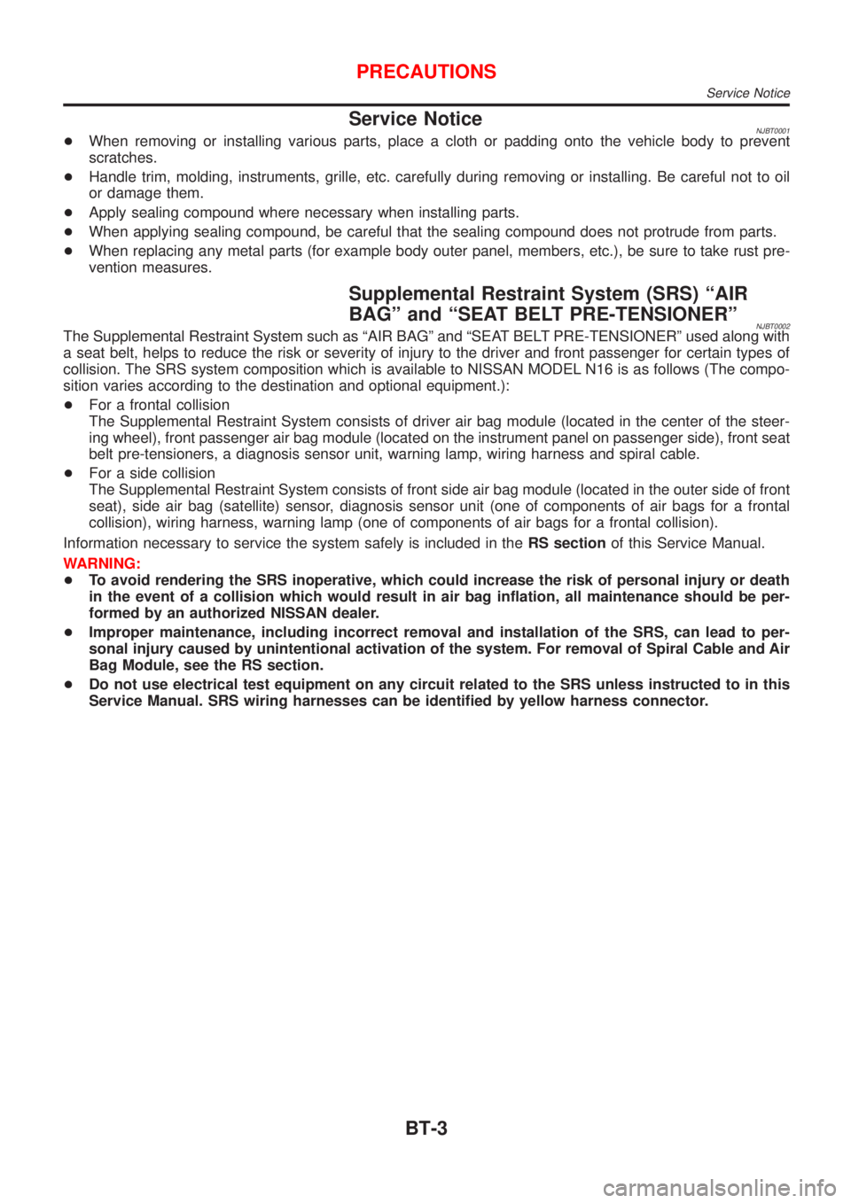
Service NoticeNJBT0001+When removing or installing various parts, place a cloth or padding onto the vehicle body to prevent
scratches.
+Handle trim, molding, instruments, grille, etc. carefully during removing or installing. Be careful not to oil
or damage them.
+Apply sealing compound where necessary when installing parts.
+When applying sealing compound, be careful that the sealing compound does not protrude from parts.
+When replacing any metal parts (for example body outer panel, members, etc.), be sure to take rust pre-
vention measures.
Supplemental Restraint System (SRS) ªAIR
BAGº and ªSEAT BELT PRE-TENSIONERº
NJBT0002The Supplemental Restraint System such as ªAIR BAGº and ªSEAT BELT PRE-TENSIONERº used along with
a seat belt, helps to reduce the risk or severity of injury to the driver and front passenger for certain types of
collision. The SRS system composition which is available to NISSAN MODEL N16 is as follows (The compo-
sition varies according to the destination and optional equipment.):
+For a frontal collision
The Supplemental Restraint System consists of driver air bag module (located in the center of the steer-
ing wheel), front passenger air bag module (located on the instrument panel on passenger side), front seat
belt pre-tensioners, a diagnosis sensor unit, warning lamp, wiring harness and spiral cable.
+For a side collision
The Supplemental Restraint System consists of front side air bag module (located in the outer side of front
seat), side air bag (satellite) sensor, diagnosis sensor unit (one of components of air bags for a frontal
collision), wiring harness, warning lamp (one of components of air bags for a frontal collision).
Information necessary to service the system safely is included in theRS sectionof this Service Manual.
WARNING:
+To avoid rendering the SRS inoperative, which could increase the risk of personal injury or death
in the event of a collision which would result in air bag inflation, all maintenance should be per-
formed by an authorized NISSAN dealer.
+Improper maintenance, including incorrect removal and installation of the SRS, can lead to per-
sonal injury caused by unintentional activation of the system. For removal of Spiral Cable and Air
Bag Module, see the RS section.
+Do not use electrical test equipment on any circuit related to the SRS unless instructed to in this
Service Manual. SRS wiring harnesses can be identified by yellow harness connector.
PRECAUTIONS
Service Notice
BT-3
Page 1925 of 2493
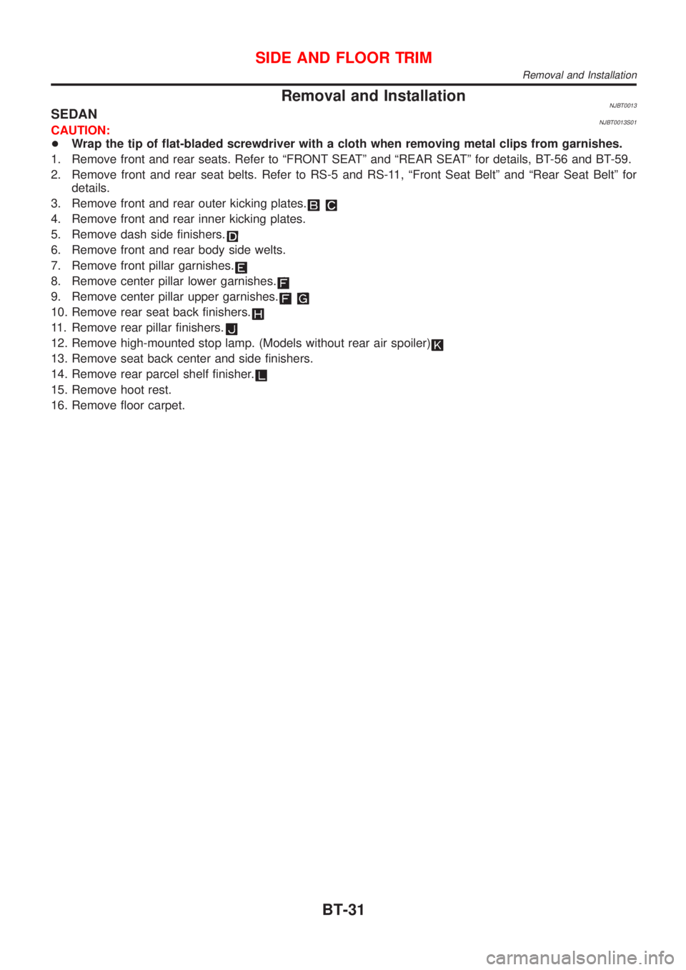
Removal and InstallationNJBT0013SEDANNJBT0013S01CAUTION:
+Wrap the tip of flat-bladed screwdriver with a cloth when removing metal clips from garnishes.
1. Remove front and rear seats. Refer to ªFRONT SEATº and ªREAR SEATº for details, BT-56 and BT-59.
2. Remove front and rear seat belts. Refer to RS-5 and RS-11, ªFront Seat Beltº and ªRear Seat Beltº for
details.
3. Remove front and rear outer kicking plates.
4. Remove front and rear inner kicking plates.
5. Remove dash side finishers.
6. Remove front and rear body side welts.
7. Remove front pillar garnishes.
8. Remove center pillar lower garnishes.
9. Remove center pillar upper garnishes.
10. Remove rear seat back finishers.
11. Remove rear pillar finishers.
12. Remove high-mounted stop lamp. (Models without rear air spoiler)
13. Remove seat back center and side finishers.
14. Remove rear parcel shelf finisher.
15. Remove hoot rest.
16. Remove floor carpet.
SIDE AND FLOOR TRIM
Removal and Installation
BT-31
Page 1928 of 2493
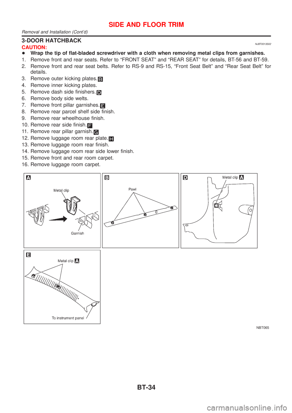
3-DOOR HATCHBACKNJBT0013S02CAUTION:
+Wrap the tip of flat-bladed screwdriver with a cloth when removing metal clips from garnishes.
1. Remove front and rear seats. Refer to ªFRONT SEATº and ªREAR SEATº for details, BT-56 and BT-59.
2. Remove front and rear seat belts. Refer to RS-9 and RS-15, ªFront Seat Beltº and ªRear Seat Beltº for
details.
3. Remove outer kicking plates.
4. Remove inner kicking plates.
5. Remove dash side finishers.
6. Remove body side welts.
7. Remove front pillar garnishes.
8. Remove rear parcel shelf side finish.
9. Remove rear wheelhouse finish.
10. Remove rear side finish.
11. Remove rear pillar garnish.
12. Remove luggage room rear plate.
13. Remove luggage room rear finish.
14. Remove luggage room rear side lower finish.
15. Remove front and rear room carpet.
16. Remove luggage room carpet.
NBT065
SIDE AND FLOOR TRIM
Removal and Installation (Cont'd)
BT-34
Page 1930 of 2493
5-DOOR HATCHBACKNJBT0013S03CAUTION:
+Wrap the tip of flat-bladed screwdriver with a cloth when removing metal clips from garnishes.
1. Remove front and rear seats. Refer to ªFRONT SEATº and ªREAR SEATº for details, BT-56 and BT-59.
2. Remove front and rear seat belts. Refer to RS-7 and RS-15, ªFront Seat Beltº and ªRear Seat Beltº for
details.
3. Remove front and rear outer kicking plates.
4. Remove front and rear inner kicking plates.
5. Remove dash side finishers.
6. Remove front and rear body side welts.
7. Remove front pillar garnishes.
8. Remove center pillar lower garnishes.
9. Remove center pillar upper garnishes.
10. Remove rear parcel shelf side finish.
11. Remove rear pillar garnish.
12. Remove rear wheelhouse finish.
13. Remove luggage room rear plate.
14. Remove luggage room rear finish.
15. Remove luggage room rear side lower finish.
16. Remove front and rear room carpet.
17. Remove luggage room carpet.
SIDE AND FLOOR TRIM
Removal and Installation (Cont'd)
BT-36
Page 1937 of 2493
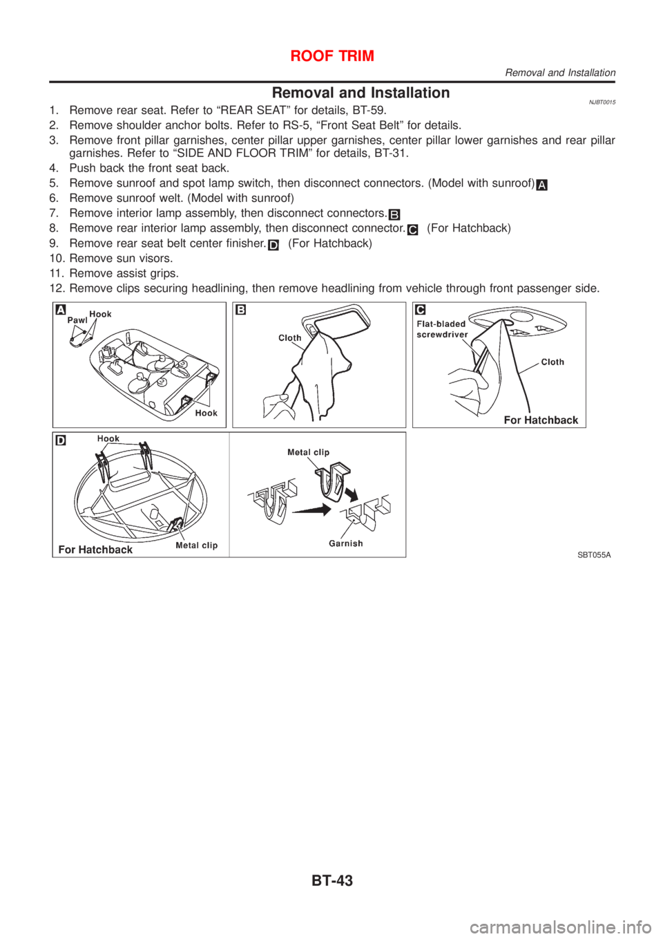
Removal and InstallationNJBT00151. Remove rear seat. Refer to ªREAR SEATº for details, BT-59.
2. Remove shoulder anchor bolts. Refer to RS-5, ªFront Seat Beltº for details.
3. Remove front pillar garnishes, center pillar upper garnishes, center pillar lower garnishes and rear pillar
garnishes. Refer to ªSIDE AND FLOOR TRIMº for details, BT-31.
4. Push back the front seat back.
5. Remove sunroof and spot lamp switch, then disconnect connectors. (Model with sunroof)
6. Remove sunroof welt. (Model with sunroof)
7. Remove interior lamp assembly, then disconnect connectors.
8. Remove rear interior lamp assembly, then disconnect connector.(For Hatchback)
9. Remove rear seat belt center finisher.
(For Hatchback)
10. Remove sun visors.
11. Remove assist grips.
12. Remove clips securing headlining, then remove headlining from vehicle through front passenger side.
SBT055A
ROOF TRIM
Removal and Installation
BT-43
Page 1973 of 2493
HEATER &
AIR CONDITIONER
SECTION
HA
CONTENTS
PRECAUTIONS...............................................................2
Supplemental Restraint System (SRS)²AIR
BAG²and²SEAT BELT PRE-TENSIONER²...............2
Precautions for Working with HFC-134a (R-134a) .....2
General Refrigerant Precautions .................................2
Precautions for Refrigerant Connection ......................3
Precautions for Servicing Compressor ........................5
Precautions for Service Equipment .............................6
Wiring Diagrams and Trouble Diagnosis .....................8
PREPARATION...............................................................9
Special Service Tools ..................................................9
HFC-134a (R-134a) Service Tools and
Equipment .................................................................. 11
DESCRIPTION...............................................................13
Refrigeration System .................................................13
CSV613 Variable Displacement Compressor............14
Component Layout ....................................................18
Control Operation ......................................................19
Discharge Air Flow.....................................................20
System Description ....................................................21
TROUBLE DIAGNOSES................................................22
Component Location..................................................22
Wiring Diagram - Heater............................................24
Circuit Diagram - Air Conditioner...............................26
Wiring Diagram - A/C, M - .........................................27
How to Perform Trouble Diagnoses for Quick
and Accurate Repair ..................................................39
Operational Check .....................................................40
Intake Door ................................................................42
Mode Door .................................................................46Air Mix Door ...............................................................48
Max Hot Door (For Scandinavia and Cold Spec
Models) ......................................................................50
Blower Motor..............................................................54
Magnet Clutch............................................................61
Insufficient Cooling ....................................................74
Insufficient Heating ....................................................82
Noise ..........................................................................83
SERVICE PROCEDURE................................................84
HFC-134a (R-134a) Service Procedure ....................84
Maintenance of Lubricant Quantity in
Compressor ...............................................................86
Compressor ...............................................................89
Compressor Clutch - CSV613 (CALSONIC
make) .........................................................................90
Heater & Cooling Unit (Heater Core) ........................94
A/C Evaporator ..........................................................94
Blower Unit ................................................................95
Refrigerant Lines .......................................................97
Belt ...........................................................................101
Idle Air Control Valve (IACV) - Auxiliary Air
Control (AAC) Valve ................................................102
Ventilation Air Filter ..................................................102
SERVICE DATA AND SPECIFICATIONS (SDS).......103
Compressor .............................................................103
Lubricant ..................................................................103
Refrigerant ...............................................................103
Engine Idling Speed (When A/C is On)...................103
Belt Tension .............................................................103