Page 335 of 2493
If results are unsatisfactory, perform Fuel Pressure Regulator
Check, EC-39.
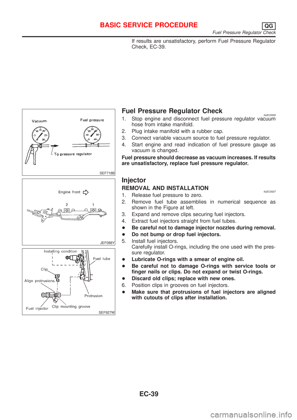
SEF718B
Fuel Pressure Regulator CheckNJEC00261. Stop engine and disconnect fuel pressure regulator vacuum
hose from intake manifold.
2. Plug intake manifold with a rubber cap.
3. Connect variable vacuum source to fuel pressure regulator.
4. Start engine and read indication of fuel pressure gauge as
vacuum is changed.
Fuel pressure should decrease as vacuum increases. If results
are unsatisfactory, replace fuel pressure regulator.
JEF088Y
SEF927W
Injector
REMOVAL AND INSTALLATIONNJEC00271. Release fuel pressure to zero.
2. Remove fuel tube assemblies in numerical sequence as
shown in the Figure at left.
3. Expand and remove clips securing fuel injectors.
4. Extract fuel injectors straight from fuel tubes.
+Be careful not to damage injector nozzles during removal.
+Do not bump or drop fuel injectors.
5. Install fuel injectors.
Carefully install O-rings, including the one used with the pres-
sure regulator.
+Lubricate O-rings with a smear of engine oil.
+Be careful not to damage O-rings with service tools or
finger nails or clips. Do not expand or twist O-rings.
+Discard old clips; replace with new ones.
6. Position clips in grooves on fuel injectors.
+Make sure that protrusions of fuel injectors are aligned
with cutouts of clips after installation.
BASIC SERVICE PROCEDUREQG
Fuel Pressure Regulator Check
EC-39
Page 338 of 2493
SEF933W
SEF284G
+Method B
a) Remove No. 1 ignition coil.
b) Connect No. 1 ignition coil and No. 1 spark plug with suitable
high-tension wire as shown, and attach timing light clamp to
this wire.
c) Check ignition timing.
SEF166Y
PreparationNJEC0592+Make sure that the following parts are in good order.
a)Battery
b)Ignition system
c)Engine oil and coolant levels
d)Fuses
e)ECM harness connector
f)Vacuum hoses
g)Air intake system
(Oil filler cap, oil level gauge, etc.)
BASIC SERVICE PROCEDUREQG
How to Check Idle Speed and Ignition Timing (Cont'd)
EC-42
Page 339 of 2493

h)Fuel pressure
i)Engine compression
j)EGR valve operation
k)Throttle valve
l)EVAP system
+On models equipped with air conditioner, checks should
be carried out while the air conditioner is ªOFFº.
+When checking idle speed on models equipped with A/T,
ignition timing and mixture ratio, checks should be carried
out while shift lever is in ªPº or ªNº position.
+When measuring ªCOº percentage, insert probe more
than 40 cm (15.7 in) into tail pipe.
+Turn off headlamps, heater blower, rear window defogger.
+On vehicles equipped with daytime light systems, set
lighting switch to the 1st position to light only small
lamps.
+Keep front wheels pointed straight ahead.
+If engine stops immediately after starting or idle condition
is unstable, perform the following to initialize IACV-AAC
valve:
a)Stop engine and wait 9 seconds.
b)Turn ignition ªONº and wait 1 second.
c)Turn ignition ªOFFº and wait 9 seconds.
+Make sure the cooling fan has stopped.
BASIC SERVICE PROCEDUREQG
Preparation (Cont'd)
EC-43
Page 341 of 2493
Inspection ProcedureNJEC0593
1 INSPECTION START
1. Visually check the following:
+Air cleaner clogging
+Hoses and ducts for leaks
+EGR valve operation
+Electrical connectors
+Gasket
+Throttle valve and throttle position sensor operation
2. Start engine and warm it up until engine coolant temperature indicator points to the middle of gauge.
Ensure engine stays below 1,000 rpm.
SEF090Y
3. Open engine hood and run engine at about 2,000 rpm for about 2 minutes under no-load.
SEF977U
4. Make sure that no DTC is displayed with CONSULT-II or GST.
OK or NG
OK©GO TO 3.
NG©GO TO 2.
2 REPAIR OR REPLACE
Repair or replace components as necessary according to corresponding ªDiagnostic Procedureº.
©GO TO 3.
BASIC SERVICE PROCEDUREQG
Inspection Procedure
EC-45
Page 342 of 2493
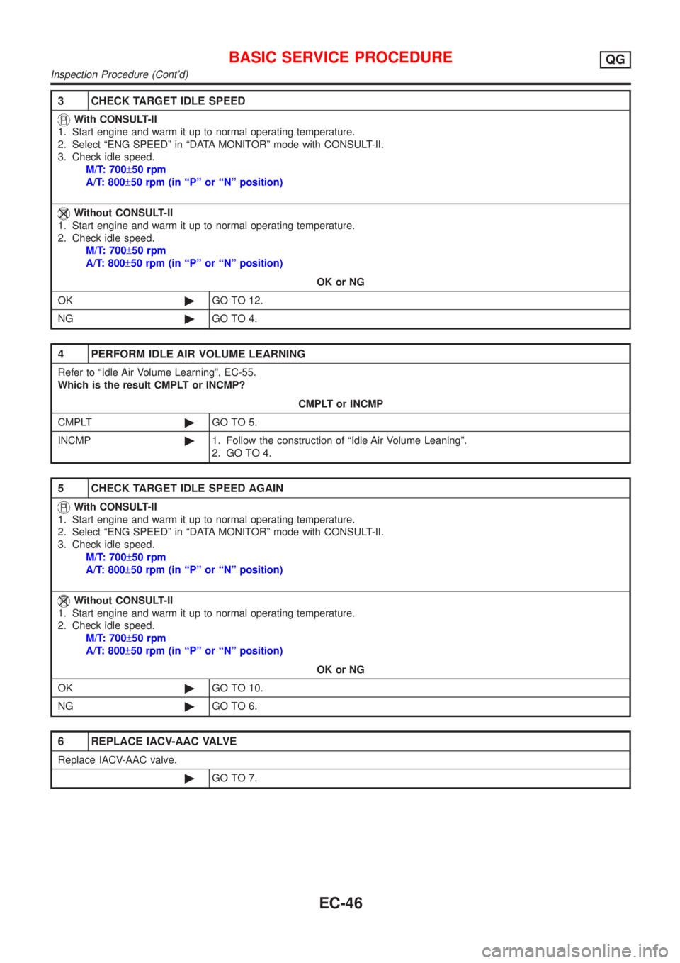
3 CHECK TARGET IDLE SPEED
With CONSULT-II
1. Start engine and warm it up to normal operating temperature.
2. Select ªENG SPEEDº in ªDATA MONITORº mode with CONSULT-II.
3. Check idle speed.
M/T: 700±50 rpm
A/T: 800±50 rpm (in ªPº or ªNº position)
Without CONSULT-II
1. Start engine and warm it up to normal operating temperature.
2. Check idle speed.
M/T: 700±50 rpm
A/T: 800±50 rpm (in ªPº or ªNº position)
OK or NG
OK©GO TO 12.
NG©GO TO 4.
4 PERFORM IDLE AIR VOLUME LEARNING
Refer to ªIdle Air Volume Learningº, EC-55.
Which is the result CMPLT or INCMP?
CMPLT or INCMP
CMPLT©GO TO 5.
INCMP©1. Follow the construction of ªIdle Air Volume Leaningº.
2. GO TO 4.
5 CHECK TARGET IDLE SPEED AGAIN
With CONSULT-II
1. Start engine and warm it up to normal operating temperature.
2. Select ªENG SPEEDº in ªDATA MONITORº mode with CONSULT-II.
3. Check idle speed.
M/T: 700±50 rpm
A/T: 800±50 rpm (in ªPº or ªNº position)
Without CONSULT-II
1. Start engine and warm it up to normal operating temperature.
2. Check idle speed.
M/T: 700±50 rpm
A/T: 800±50 rpm (in ªPº or ªNº position)
OK or NG
OK©GO TO 10.
NG©GO TO 6.
6 REPLACE IACV-AAC VALVE
Replace IACV-AAC valve.
©GO TO 7.
BASIC SERVICE PROCEDUREQG
Inspection Procedure (Cont'd)
EC-46
Page 343 of 2493
7 PERFORM IDLE AIR VOLUME LEARNING
Refer to ªIdle Air Volume Learningº, EC-55.
Which is the result CMPLT or INCMP?
CMPLT or INCMP
CMPLT©GO TO 8.
INCMP©1. Follow the construction of ªIdle Air Volume Learningº.
2. GO TO 4.
8 CHECK TARGET IDLE SPEED AGAIN
With CONSULT-II
1. Start engine and warm it up to normal operating temperature.
2. Select ªENG SPEEDº in ªDATA MONITORº mode with CONSULT-II.
3. Check idle speed.
M/T: 700±50 rpm
A/T: 800±50 rpm (in ªPº or ªNº position)
Without CONSULT-II
1. Start engine and warm it up to normal operating temperature.
2. Check idle speed.
M/T: 700±50 rpm
A/T: 800±50 rpm (in ªPº or ªNº position)
OK or NG
OK©GO TO 10.
NG©GO TO 9.
9 CHECK ECM FUNCTION
1. Substitute another known-good ECM to check ECM function. (ECM may be the cause of a problem, but this is rarely
the case.)
2. Perform initialization of NATS system and registration of NATS ignition key IDs. Refer to ªNATS (Nissan Anti-Theft
System)º, EC-72.
©GO TO 4.
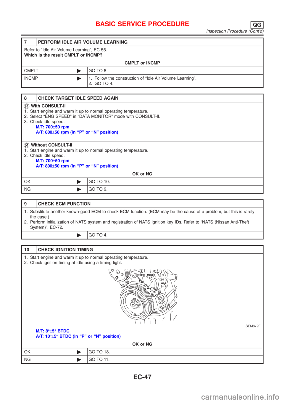
10 CHECK IGNITION TIMING
1. Start engine and warm it up to normal operating temperature.
2. Check ignition timing at idle using a timing light.
SEM872F
M/T: 8ɱ5É BTDC
A/T: 10ɱ5É BTDC (in ªPº or ªNº position)
OK or NG
OK©GO TO 18.
NG©GO TO 11.
BASIC SERVICE PROCEDUREQG
Inspection Procedure (Cont'd)
EC-47
Page 344 of 2493
11 CHECK TIMING CHAIN INSTALLATION
Check timing chain installation. Refer to EM-27, ªInstallationº.
OK or NG
OK©GO TO 9.
NG©1. Repair the timing chain installation.
2. GO TO 4.
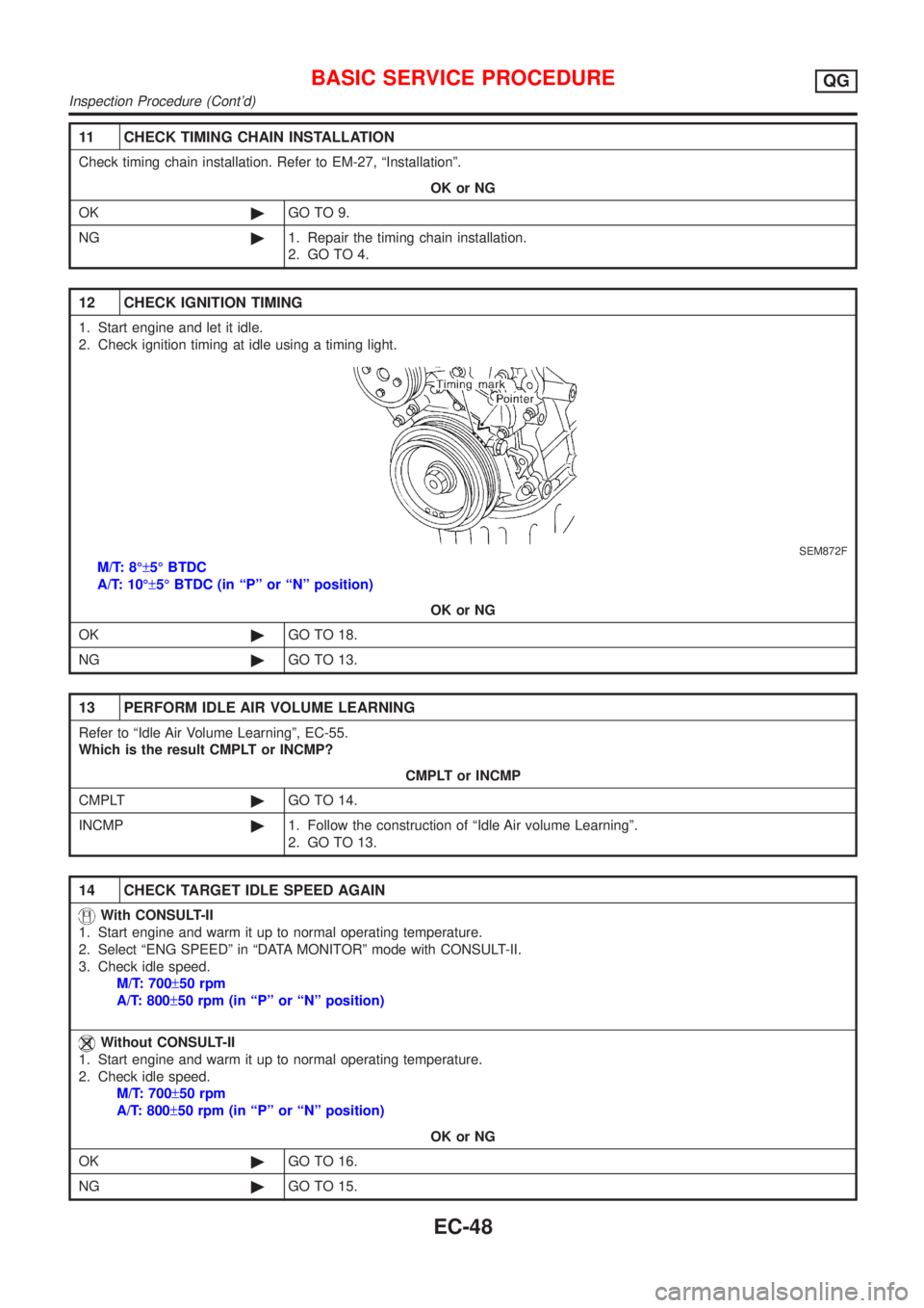
12 CHECK IGNITION TIMING
1. Start engine and let it idle.
2. Check ignition timing at idle using a timing light.
SEM872F
M/T: 8ɱ5É BTDC
A/T: 10ɱ5É BTDC (in ªPº or ªNº position)
OK or NG
OK©GO TO 18.
NG©GO TO 13.
13 PERFORM IDLE AIR VOLUME LEARNING
Refer to ªIdle Air Volume Learningº, EC-55.
Which is the result CMPLT or INCMP?
CMPLT or INCMP
CMPLT©GO TO 14.
INCMP©1. Follow the construction of ªIdle Air volume Learningº.
2. GO TO 13.
14 CHECK TARGET IDLE SPEED AGAIN
With CONSULT-II
1. Start engine and warm it up to normal operating temperature.
2. Select ªENG SPEEDº in ªDATA MONITORº mode with CONSULT-II.
3. Check idle speed.
M/T: 700±50 rpm
A/T: 800±50 rpm (in ªPº or ªNº position)
Without CONSULT-II
1. Start engine and warm it up to normal operating temperature.
2. Check idle speed.
M/T: 700±50 rpm
A/T: 800±50 rpm (in ªPº or ªNº position)
OK or NG
OK©GO TO 16.
NG©GO TO 15.
BASIC SERVICE PROCEDUREQG
Inspection Procedure (Cont'd)
EC-48
Page 346 of 2493
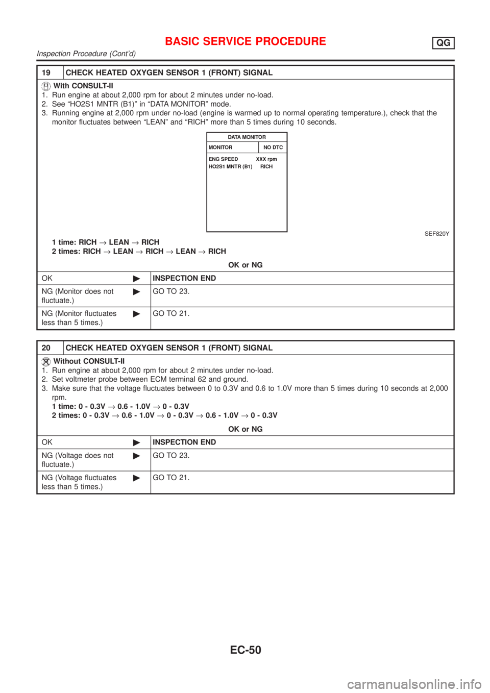
19 CHECK HEATED OXYGEN SENSOR 1 (FRONT) SIGNAL
With CONSULT-II
1. Run engine at about 2,000 rpm for about 2 minutes under no-load.
2. See ªHO2S1 MNTR (B1)º in ªDATA MONITORº mode.
3. Running engine at 2,000 rpm under no-load (engine is warmed up to normal operating temperature.), check that the
monitor fluctuates between ªLEANº and ªRICHº more than 5 times during 10 seconds.
SEF820Y
1 time: RICH®LEAN®RICH
2 times: RICH®LEAN®RICH®LEAN®RICH
OK or NG
OK©INSPECTION END
NG (Monitor does not
fluctuate.)©GO TO 23.
NG (Monitor fluctuates
less than 5 times.)©GO TO 21.
20 CHECK HEATED OXYGEN SENSOR 1 (FRONT) SIGNAL
Without CONSULT-II
1. Run engine at about 2,000 rpm for about 2 minutes under no-load.
2. Set voltmeter probe between ECM terminal 62 and ground.
3. Make sure that the voltage fluctuates between 0 to 0.3V and 0.6 to 1.0V more than 5 times during 10 seconds at 2,000
rpm.
1 time: 0 - 0.3V®0.6 - 1.0V®0 - 0.3V
2 times: 0 - 0.3V®0.6 - 1.0V®0 - 0.3V®0.6 - 1.0V®0 - 0.3V
OK or NG
OK©INSPECTION END
NG (Voltage does not
fluctuate.)©GO TO 23.
NG (Voltage fluctuates
less than 5 times.)©GO TO 21.
BASIC SERVICE PROCEDUREQG
Inspection Procedure (Cont'd)
EC-50