2001 LAND ROVER FREELANDER light
[x] Cancel search: lightPage 44 of 1007

GENERAL INFORMATION
03-13
Self-locking bolts and screws
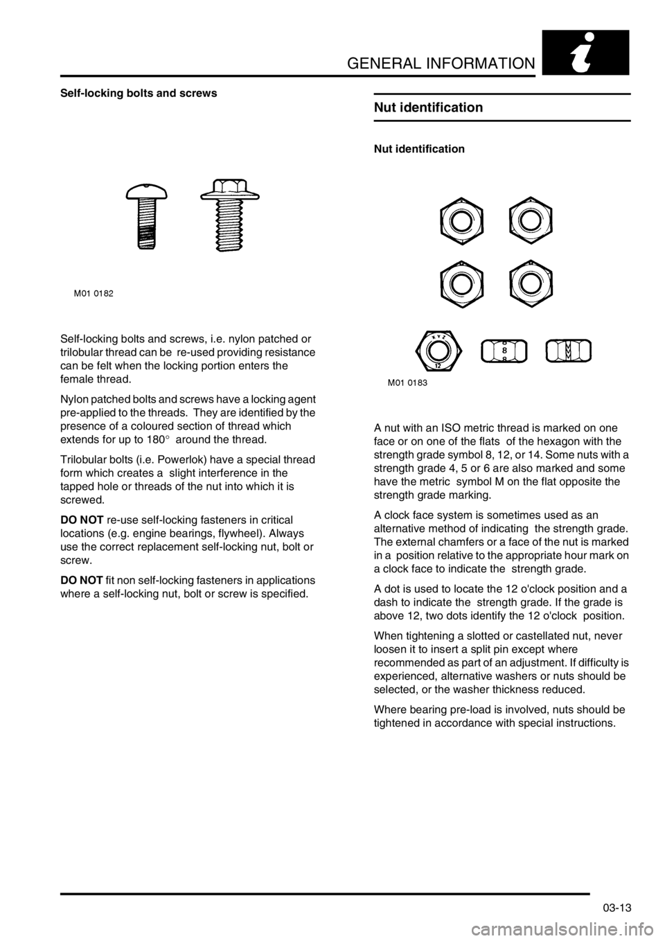
Self-locking bolts and screws, i.e. nylon patched or
trilobular thread can be re-used providing resistance
can be felt when the locking portion enters the
female thread.
Nylon patched bolts and screws have a locking agent
pre-applied to the threads. They are identified by the
presence of a coloured section of thread which
extends for up to 180° around the thread.
Trilobular bolts (i.e. Powerlok) have a special thread
form which creates a slight interference in the
tapped hole or threads of the nut into which it is
screwed.
DO NOT re-use self-locking fasteners in critical
locations (e.g. engine bearings, flywheel). Always
use the correct replacement self-locking nut, bolt or
screw.
DO NOT fit non self-locking fasteners in applications
where a self-locking nut, bolt or screw is specified.
Nut identification
Nut identification
A nut with an ISO metric thread is marked on one
face or on one of the flats of the hexagon with the
strength grade symbol 8, 12, or 14. Some nuts with a
strength grade 4, 5 or 6 are also marked and some
have the metric symbol M on the flat opposite the
strength grade marking.
A clock face system is sometimes used as an
alternative method of indicating the strength grade.
The external chamfers or a face of the nut is marked
in a position relative to the appropriate hour mark on
a clock face to indicate the strength grade.
A dot is used to locate the 12 o'clock position and a
dash to indicate the strength grade. If the grade is
above 12, two dots identify the 12 o'clock position.
When tightening a slotted or castellated nut, never
loosen it to insert a split pin except where
recommended as part of an adjustment. If difficulty is
experienced, alternative washers or nuts should be
selected, or the washer thickness reduced.
Where bearing pre-load is involved, nuts should be
tightened in accordance with special instructions.
Page 47 of 1007

GENERAL INFORMATION
03-16
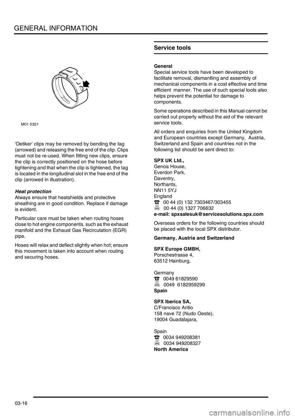
'Oetiker' clips may be removed by bending the tag
(arrowed) and releasing the free end of the clip. Clips
must not be re-used. When fitting new clips, ensure
the clip is correctly positioned on the hose before
tightening and that when the clip is tightened, the tag
is located in the longitudinal slot in the free end of the
clip (arrowed in illustration).
Heat protection
Always ensure that heatshields and protective
sheathing are in good condition. Replace if damage
is evident.
Particular care must be taken when routing hoses
close to hot engine components, such as the exhaust
manifold and the Exhaust Gas Recirculation (EGR)
pipe.
Hoses will relax and deflect slightly when hot; ensure
this movement is taken into account when routing
and securing hoses.
Service tools
General
Special service tools have been developed to
facilitate removal, dismantling and assembly of
mechanical components in a cost effective and time
efficient manner. The use of such special tools also
helps prevent the potential for damage to
components.
Some operations described in this Manual cannot be
carried out properly without the aid of the relevant
service tools.
All orders and enquiries from the United Kingdom
and European countries except Germany, Austria,
Switzerland and Spain and countries not in the
following list should be sent direct to:
SPX UK Ltd.,
Genoa House,
Everdon Park,
Daventry,
Northants,
NN11 5YJ
England
( 00 44 (0) 132 7303467/303455
) 00 44 (0) 1327 706632
e-mail: [email protected]
Overseas orders for the following countries should
be placed with the local SPX distributor.
Germany, Austria and Switzerland
SPX Europe GMBH,
Porschestrasse 4,
63512 Hainburg,
Germany
( 0049 61829590
) 0049 6182959299
Spain
SPX Iberica SA,
C/Francisco Aritio
158 nave 72 (Nudo Oeste),
19004 Guadalajara,
Spain
( 0034 949208381
) 0034 949208327
North America
Page 48 of 1007

GENERAL INFORMATION
03-17
SPX Corporation,
665, Eisenhower Drive,
Owatonna,
MN 55060,
USA
( 0018 772979110
) 0018 005787375
Australia
SPX Australia,
28, Clayton Road,
Notting Hill,
Victoria 3168,
Australia
( 00 (61) 00395446222
) 00 (61) 0395445222
e-mail: [email protected]
Japan and East Asia
Jatek Ltd.,
5 - 53, Minawacho 2-chome,
Kohoku-ku,
Yokohama,
Kanagawa 223-0051,
Japan
( 0081 455627700
) 0081 455627800
Rolling road testing
General
IMPORTANT: Use a four wheel rolling road for
brake testing if possible.
The front and rear wheels cannot be driven
independently due to the viscous coupling. This
eliminates the need for differential lock by
progressively applying more torque to the rear
wheels if the front wheels start to slip.
DO NOT attempt to drive individual wheels with
vehicle supported on floor jacks or stands.
Four wheel rolling road
Provided that front and rear rollers are rotating at
identical speeds and that normal workshop safety
standards are applied, there is no speed restriction
during testing, except any that may apply to the tyres.
Before testing a vehicle with anti-lock brakes on a
four wheel rolling road, disconnect the ABS
modulator. The ABS function will not work, the ABS
warning light will illuminate. Normal braking will be
available.
Two wheel rolling road
ABS will not function on a two wheel rolling road. The
ABS light will illuminate during testing. Normal
braking will be available.
If brake testing on a two wheel rolling road is
necessary, the following precautions should be
taken:
lpropeller shaft to the rear axle is removed/
disconnected;
lneutral selected in gearbox;
lhill descent control not selected.
When checking brakes, run engine at idle speed to
maintain servo vacuum.
Page 49 of 1007

GENERAL INFORMATION
03-18
Fuel handling precautions
Fuel vapour is highly inflammable and in confined
spaces is also explosive and toxic. The vapour is
heavier than air and will always fall to the lowest
level. The vapour can easily be distributed
throughout a workshop by air currents;
consequently, even a small spillage of fuel is
potentially very dangerous.
The following information provides basic precautions
which must be observed if petrol (gasoline) is to be
handled safely. It also outlines other areas of risk
which must not be ignored. This information is issued
for basic guidance only, if in doubt consult your local
Fire Officer.
General
Always have a fire extinguisher containing FOAM,
CO
2, GAS or POWDER close at hand when handling
or draining fuel or when dismantling fuel systems.
Fire extinguishers should also be located in areas
where fuel containers are stored.
Always disconnect the vehicle battery before
carrying out dismantling or draining work on a fuel
system.
Whenever fuel is being handled, drained or stored, or
when fuel systems are being dismantled, all forms of
ignition must be extinguished or removed; any
leadlamps must be flameproof and kept clear of
spillage.
WARNING: No one should be permitted to repair
components associated with fuel without first
having specialist training.
WARNING: Do not remove fuel system
components while the vehicle is over a pit.Fuel tank draining
Fuel tank draining should be carried out in
accordance with the procedure outlined in the FUEL
DELIVERY section of this manual and observing the
following precautions:
WARNING: Fuel must not be extracted or drained
from any vehicle while it is over a pit. Extraction
or draining of fuel must be carried out in a well
ventilated area.
The capacity of containers must be more than
adequate for the amount of fuel to be extracted or
drained. The container should be clearly marked
with its contents and placed in a safe storage
area which meets the requirements of local
authority regulations.
WARNING: When fuel has been drained from a
fuel tank the precautions governing naked lights
and ignition sources should be maintained.
Fuel tank removal
When the fuel line is secured to the fuel tank outlet by
a spring steel clip, the clip must be released before
the fuel line is disconnected or the fuel tank is
removed. This procedure will avoid the possibility of
residual petrol fumes in the fuel tank being ignited
when the clip is released.
As an added precaution, fuel tanks should have a
'FUEL VAPOUR' warning label attached to them as
soon as they are removed from the vehicle.
Fuel tank repairs
No attempt should be made to repair a plastic fuel
tank. If the structure of the tank is damaged, a new
tank must be fitted.
Body repairs
Plastic fuel pipes are particularly susceptible to heat,
even at relatively low temperature, and can be
melted by heat conducted from some distance away.
When body repairs involve the use of heat, all fuel
pipes which run in the vicinity of the repair area must
be removed, and the tank outlet plugged.
Page 69 of 1007

GENERAL DATA
04-6
Engine - K1.8 Petrol
General
Type 1.8 litre petrol, 16-valve DOHC
Cylinder arrangement 4 in-line, transverse, No.1 cylinder at front of engine
Bore 80.00 mm (3.150 in.)
Stroke 89.30 mm (3.516 in.)
Capacity 1796 cm
3 (109.59 in3)
Firing order 1-3-4-2
Compression ratio 10.5 :1 ± 0.5 :1
Direction of rotation Clockwise viewed from the front of the engine
Maximum power 88 kW (118 bhp) @ 5500 rev/min.
Maximum torque 165 Nm (223.7 lbf.ft) @ 2750 rev/min.
Idle speed 775 ± 50 rev/min.
Maximum intermittent engine speed 6750 rev/min.
Weight (fully dressed, wet) 108 kg (238 lb)
Dimensions:
⇒ Length (nominal) 654 mm (25.75 in.)
⇒ Width (nominal) 600 mm (23.62 in.)
⇒ Height (nominal) 615 mm (24.21 in.)
Spark plugs:
⇒ Type NLP 100290
⇒ Gap 1.0 mm ± 0.05 mm (0.039 in. ± 0.002 in.)
Ignition coils:
⇒ Make Nippon Denso - NEC 100730
⇒ Type 2 x twin output coils, plug top mounted; cylinders 1 & 4 and 2 & 3
⇒ Primary resistance (typical) 0.7 Ω
⇒ Secondary resistance (typical) 10 Ω
Fuel injection system:
Type Returnless fuel rail, multi-point fuel injection, electronically controlled
from ECM
Controller MEMS 3 breakerless, electronic, fully mapped engine management
system
Injectors:
⇒ Operating pressure 3.5 bar (50.8 lbf.in
2)
⇒ Fuel flow rate 117 g/min. @ 3.0 bar (4.13 fl.oz/min. @ 43.5 lbf. in
2)
Valve operation Self-adjusting, lightweight hydraulic tappets operated directly by
camshafts
Emissions standard ECD3
Cylinder block:
Material Aluminium alloy
Cylinder liner type Damp, bottom half stepped - sliding fit into lower part of cylinder block
Cylinder liner bore:
⇒ RED grade A 80.000 - 80.015 mm (3.1496 - 3.1501 in.)
⇒ BLUE grade B 80.016 - 80.030 mm (3.1502 - 3.1508 in.)
Page 71 of 1007

GENERAL DATA
04-8
Pistons
Type Aluminium alloy, tin plated, thermal expansion with offset gudgeon pin
Piston diameter:
⇒ Grade A 79.975 - 79.990 mm (3.1486 - 3.1492 in.)
⇒ Grade B 79.991 - 80.005 mm (3.1492 - 3.1498 in.)
Clearance in bore 0.01 - 0.04 mm (0.0004 - 0.0016 in.)
Maximum ovality 0.30 mm (0.012 in.)
Piston rings:
Type: 2 compression, 1 oil control
⇒ Top compression ring Barrel faced, granulite coated
⇒ 2nd compression ring Tapered, phosphate coated
⇒ Oil control ring Nitrided ring with radii and spring
New ring to groove clearance:
⇒ Top compression ring 0.040 - 0.072 mm (0.0016 - 0.0028 in.)
⇒ 2nd compression ring 0.030 - 0.062 mm (0.0012 - 0.0024 in.)
⇒ Oil control ring 0.010 - 0.180 mm (0.0004 - 0.0071 in.)
Ring fitted gap 20 mm (0.75 in) from top of bore:
⇒ Top compression ring 0.20 - 0.35 mm (0.008 - 0.014 in.)
⇒ 2nd compression ring 0.28 - 0.48 mm (0.011 - 0.019 in.)
⇒ Oil control ring 0.15 - 0.40 mm (0.006 - 0.016 in.)
Piston ring width:
⇒ Top compression ring 0.978 - 0.990 mm (0.0385 - 0.0390 in.)
⇒ 2nd compression ring 1.178 - 1.190 mm (0.0464 - 0.0469 in.)
⇒ Oil control ring 0.33 - 0.38 mm (0.0130 - 0.0150 in.)
Camshaft
Type DOHC acting directly on tappets, incorporates target/reluctor for
camshaft sensor
Bearings 6 per camshaft, direct line bored
Drive Toothed belt driven from crankshaft gear, automatically tensioned
Camshaft end-float 0.06 - 0.19 mm (0.002 - 0.007 in.)
⇒ Service limit 0.30 mm (0.012 in.)
Bearing clearance 0.060 - 0.094 mm (0.0024 - 0.0037 in.)
⇒ Service limit 0.15 mm (0.006 in.)
Tappets
Type Self-adjusting lightweight hydraulic tappets, operated directly from
camshafts
Tappet outside diameter 32.959 - 32.975 mm (1.2976 - 1.2982 in.)
Valve timing:
Inlet valves:
⇒ Opens
⇒ Closes
⇒ Maximum lift12° BTDC
52° ABDC
8.8 mm (0.35 in.)
Exhaust valves:
⇒ Opens
⇒ Closes
⇒ Maximum lift52° BBDC
12° ATDC
8.8 mm (0.35 in.) General
Page 74 of 1007

GENERAL DATA
04-11
Engine - KV6 Petrol
General
Type:
⇒ Up to 03 Model Year
⇒ From 03 Model Year2.5 litre V6, 24 valve, air assisted direct fuel injection petrol, water
cooled, transverse mounted
2.5 litre V6, 24 valve, direct fuel injection petrol, water cooled,
transverse mounted
Cylinder arrangement: 90° V6, numbered from the front of the engine
⇒ Left bank Cylinders 1, 3 and 5
⇒ Right bank Cylinders 2, 4 and 6
Bore (nominal) 80 mm (3.15 in.)
Stroke 82.8 mm (3.26 in.)
Capacity 2497 cm
3 (152.37 in3)
Firing order 1-6-5-4-3-2
Compression ratio 10.5 : 1 ± 0.5 : 1
Direction of rotation Clockwise viewed from front of engine
Maximum power 130 kW (177 bhp) @ 6500 rev/min.
Maximum torque 240.0 Nm (177 lbf.ft) @ 4000 rev/min.
Maximum engine speed:
⇒ Continuous 6500 rev/min.
⇒ Intermittent 6750 rev/min.
Idle speed 750 rev/min. ± 50 rev/min.
Weight (fully dressed, wet) 154 kg (340 lb)
Dimensions (dressed):
⇒ Length (nominal) 770 mm (30.3 in.)
⇒ Width (nominal) 750 mm (29.5 in.)
⇒ Height (nominal) 750 mm (29.5 in.)
Valve operation Self-adjusting lightweight hydraulic tappets operated directly by the
camshafts
Fuel injection system:
⇒ Make - Up to 03 Model Year
⇒ Make - From 03 Model YearSiemens engine management system
Siemens engine management system
⇒ Type - Up to 03 Model Year
⇒ Type - From 03 Model YearMulti-point, air assisted fuel injection controlled by ECM, electro-
mechanical injectors with twin sprays targeted on to back of inlet
valves
Multi-point fuel injection controlled by ECM, electro-mechanical
injectors with quadruple sprays targeted on to back of inlet valves
Inlet manifold Variable geometry
Spark plugs
⇒ Type
⇒ Plug gapNLP 100290
1.0 mm ± 0.05 mm (0.039 in. ± 0.002 in.)
Coils:
⇒ Make - Up to 03 Model Year
⇒ Make - From 03 Model Year
⇒ Type - Up to 03 Model Year
⇒ Type - From 03 Model YearBREMR
Champion BAE 403H
6 x coils (3 x plug top, 3 x remote mounted)
6 x coils (6 x plug top)
Emissions standard ECD3
Page 122 of 1007

TORQUE WRENCH SETTINGS
06-19
Manual Gearbox – PG1
+ Apply sealant, Part No. STC 50552 to threads of 2 top bolts
TORQUE DESCRIPTION METRIC IMPERIAL
Clutch slave cylinder mounting bracket to gearbox bolts 25 Nm 18 lbf.ft
Drain plug35 Nm 26 lbf.ft
Filler / level plug35 Nm 26 lbf.ft
1st. gear switch24 Nm 18 lbf.ft
Front cover plate to gearbox bolt and nut 9 Nm 7 lbf.ft
Gearbox to engine bolts
+80 Nm 59 lbf.ft
Gearbox to sump bolts 45 Nm 33 lbf.ft
Gear change steady rod to mounting bracket bolt 25 Nm 18 lbf.ft
Lifting bracket to gearbox bolt 45 Nm 33 lbf.ft
LH engine mounting to gearbox bolts 65 Nm 48 lbf.ft
LH engine mounting to gearbox bolts 80 Nm 59 lbf.ft
Reverse light switch 24 Nm 18 lbf.ft