2001 LAND ROVER FREELANDER brake
[x] Cancel search: brakePage 33 of 1007

GENERAL INFORMATION
03-2
Environmental Protection Precautions
It is illegal to pour used oil on to the ground, down
sewers or drains, or into water courses.
Burning of used engine oil in small space heaters or
boilers should only be considered for units of
approved design and in compliance with the
equipment manufacturer's recommendations. The
heating system must meet the regulatory standards
of HMIP for small burners of less than 0.4 MW. If in
doubt check with the appropriate local authority and/
or manufacturer of the approved appliance.
Dispose of used oil and filters through authorised
waste disposal contractors and licensed waste
disposal sites, or through the waste oil reclamation
trade. If in doubt, contact the Local Authority for
advice on disposal facilities.
Safety instructions
Whenever possible, use a lift or pit when working
beneath vehicle, in preference to jacking. Chock
wheels as well as applying parking brake.
Jacking
Always use the recommended jacking points. The
recommended jacking points are shown in
theLIFTING AND TOWING sub-section of the
INFORMATION section.
Always ensure that any lifting apparatus has
sufficient load capacity for the weight to be lifted.
Ensure the vehicle is standing on level ground prior
to lifting or jacking.
Apply the handbrake and chock the wheels.
WARNING: Do not work on or under a vehicle
supported only by a jack. Always support the
vehicle on safety stands.
Do not leave tools, lifting equipment, spilt oil, etc.,
around or on the work bench area. Always keep a
clean and tidy work area.
Brake shoes and pads
Always fit the correct grade and specification of
brake linings. When renewing brake pads and brake
shoes always replace as complete axle sets only.
Page 34 of 1007

GENERAL INFORMATION
03-3
Brake hydraulics
Observe the following recommendations when
working on the brake system:
lAlways use two spanners when loosening or
tightening brake pipe or hose connections.
lEnsure that hoses run in a natural curve and are
not kinked or twisted.
lFit brake pipes securely in their retaining clips
and ensure that the pipe run cannot contact a
potential chafing point.
lContainers used for hydraulic brake fluid must
be kept absolutely clean.
lDo not store hydraulic brake fluid in an unsealed
container, it will absorb water and in this
condition would be dangerous to use due to a
lowering of its boiling point.
lDo not allow hydraulic brake fluid to be
contaminated with mineral oil, or put new
hydraulic brake fluid in a container which has
previously contained mineral oil.
lDo not re-use hydraulic brake fluid previously
removed from the system.
lAlways use clean brake fluid or a recommended
alternative to clean hydraulic components.
lFit a blanking cap to a hydraulic union and a
plug to its socket, immediately after
disconnection of pipes and hoses to prevent the
ingress of dirt.
lAbsolute cleanliness must be observed when
working with hydraulic components.
lIt is imperative that the correct brake fittings are
used and that threads of components are
compatible.
Cooling system caps and plugs
Extreme care is necessary when removing engine
cooling system expansion tank caps and coolant
drain or bleed screws when the engine is hot, and
especially if it is overheated.
To avoid the possibility of scalding allow the engine
to cool before attempting coolant cap or plug
removal.
Environmental Precautions
General
This section provides general information which can
help to reduce adverse environmental impacts
incurred through the activities carried out in
workshops.
Emissions to air
Many of the activities that are carried out in
workshops emit gases and fumes which contribute to
global warming, depletion of the ozone layer and/or
the formation of photo-chemical smog at ground
level. By considering and controlling how the
workshop activities are carried out, these gases and
fumes can be minimised, thus reducing the damage
to the environment.
Exhaust fumes
Running car engines is an essential part of workshop
activities and exhaust fumes need to be ventilated to
atmosphere. However, the amount of time engines
are running and the position of the vehicle should be
carefully considered at all times, to reduce the
release of poisonous gases and minimise the
inconvenience to people living nearby.
Solvents
Some of the cleaning agents used are solvent based
and will evaporate to atmosphere if used carelessly,
or if cans are left unsealed. All solvent containers
should be firmly closed when not needed and solvent
should be used sparingly. Suitable alternative
materials may be available to replace some of the
commonly used solvents. Similarly, many paints are
solvent based and the spray should be minimised to
reduce solvent emissions.
Refrigerant
It is illegal to release any refrigerants into the
atmosphere. Discharge and replacement of these
materials from air conditioning units should only be
carried out using the correct equipment.
Checklist
Always adhere to the following:
Engines –
ldon't leave engines running unnecessarily;
lminimise testing times and check where the
exhaust fumes are being blown.
Page 38 of 1007

GENERAL INFORMATION
03-7
General fitting instructions
Precautions against damage
To avoid damage to the vehicle when carrying out
repairs, always adhere to the following:
lAlways fit wing and seat covers before
commencing work. Avoid spilling brake fluid or
battery acid on paintwork; immediately wash off
with water if this occurs.
lDisconnect the battery earth lead before starting
work, see ELECTRICAL PRECAUTIONS.
lAlways use the recommended service tool or a
satisfactory equivalent where specified.
lProtect exposed bearing surfaces, sealing
surfaces and screw threads from damage.
Component removal
Whenever possible, clean components and
surrounding area before removal.
lBlank off openings exposed by component
removal.
lImmediately seal fuel, oil or hydraulic lines when
apertures are exposed; use plastic caps or
plugs to prevent loss of fluid and ingress of dirt.
lClose open ends of oilways exposed by
component removal with tapered hardwood
plugs or conspicuous plastic plugs.
lImmediately a component is removed, place it in
a suitable container; use a separate container
for each component and its associated parts.
lClean bench and provide marking materials,
labels, containers and locking wire before
dismantling a component.
Dismantling
Observe scrupulous cleanliness when dismantling
components, particularly when brake, fuel or
hydraulic system parts are being worked on. A
particle of dirt or a cloth fragment could cause a
serious malfunction if trapped in these systems.Use the following procedures:
lBlow out all tapped holes, crevices, oilways and
fluid passages with an air line. Ensure that any
O-rings used for sealing are correctly replaced
or renewed if disturbed during the process.
lUse marking ink to identify mating parts and
ensure correct reassembly. Do not use a centre
punch or scriber to mark parts, they could
initiate cracks or distortion in marked
components.
lWire together mating parts where necessary to
prevent accidental interchange (e.g. roller
bearing components).
lWire labels on to all parts which are to be
renewed, and to parts requiring further
inspection before being passed for reassembly;
place these parts in separate containers from
those containing parts for rebuild.
lDo not discard a part due for renewal until after
comparing it with a new part to ensure that its
correct replacement has been obtained.
Cleaning components
Always use the recommended cleaning agent or
equivalent. Ensure that adequate ventilation is
provided when volatile degreasing agents are being
used. Do not use degreasing equipment for
components containing items which could be
damaged by the use of this process.
When washing under bonnet, never direct water onto
ECM, as water ingress may occur resulting in
damage to electrical components inside.
General Inspection
All components should be inspected for wear or
damage before being reassembled.
lNever inspect a component for wear or
dimensional check unless it is absolutely clean;
a slight smear of grease can conceal an
incipient failure.
lWhen a component is to be checked
dimensionally against recommended values,
use the appropriate measuring equipment
(surface plates, micrometers, dial gauges etc.).
Ensure the measuring equipment is calibrated
and in good serviceable condition.
lReject a component if its dimensions are
outside the specified tolerances, or if it appears
to be damaged.
lA part may be refitted if its critical dimension is
exactly to its tolerance limit and it appears to be
in satisfactory condition.
lUse 'Plastigauge' 12 Type PG-1 for checking
bearing surface clearances.
Page 41 of 1007

GENERAL INFORMATION
03-10
Joints and joint faces
General
Fit joints dry unless specified otherwise.
lAlways use the correct gaskets as specified.
lWhen joining compound is used, apply in a thin
uniform film to metal surfaces; take care to
prevent joining compound from entering
oilways, pipes or blind tapped holes.
lIf gaskets and/or joining compound is
recommended for use; remove all traces of old
joining material prior to reassembly. Do not use
a tool which will damage the joint faces and
smooth out any scratches or burrs using an oil
stone. Do not allow dirt or joining material to
enter any tapped holes or enclosed parts.
lPrior to reassembly, blow through any pipes,
channels or crevices with compressed air.
Locking devices
General
Always replace locking devices with one of the same
design.
Tab Washers
Always release locking tabs and fit new locking
washers, do not re-use locking tabs. Ensure the new
tab washer is the same design as that replaced.
Locking Nuts
Always use a backing spanner when loosening or
tightening locking nuts, brake and fuel pipe unions.
Roll Pins
Always fit new roll pins of an interference fit in the
hole.
Circlips
Always fit new circlips of the correct size for the
groove.
Locking wire
Always fit locking wire of the correct type. Arrange
wire so that its tension tends to tighten the bolt heads
or nuts to which it is fitted.
Keys and Keyways
Remove burrs from edges of keyways with a fine file
and clean thoroughly before attempting to refit key.
Clean and inspect key closely; keys are suitable for
refitting only if indistinguishable from new, as any
indentation may indicate the onset of wear.
Page 45 of 1007

GENERAL INFORMATION
03-14
Self-locking nuts
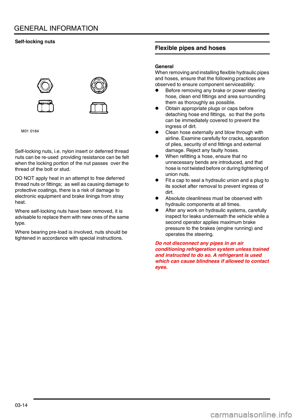
Self-locking nuts, i.e. nylon insert or deferred thread
nuts can be re-used providing resistance can be felt
when the locking portion of the nut passes over the
thread of the bolt or stud.
DO NOT apply heat in an attempt to free deferred
thread nuts or fittings; as well as causing damage to
protective coatings, there is a risk of damage to
electronic equipment and brake linings from stray
heat.
Where self-locking nuts have been removed, it is
advisable to replace them with new ones of the same
type.
Where bearing pre-load is involved, nuts should be
tightened in accordance with special instructions.
Flexible pipes and hoses
General
When removing and installing flexible hydraulic pipes
and hoses, ensure that the following practices are
observed to ensure component serviceability:
lBefore removing any brake or power steering
hose, clean end fittings and area surrounding
them as thoroughly as possible.
lObtain appropriate plugs or caps before
detaching hose end fittings, so that the ports
can be immediately covered to prevent the
ingress of dirt.
lClean hose externally and blow through with
airline. Examine carefully for cracks, separation
of plies, security of end fittings and external
damage. Reject any faulty hoses.
lWhen refitting a hose, ensure that no
unnecessary bends are introduced, and that
hose is not twisted before or during tightening of
union nuts.
lFit a cap to seal a hydraulic union and a plug to
its socket after removal to prevent ingress of
dirt.
lAbsolute cleanliness must be observed with
hydraulic components at all times.
lAfter any work on hydraulic systems, carefully
inspect for leaks underneath the vehicle while a
second operator applies maximum brake
pressure to the brakes (engine running) and
operates the steering.
Do not disconnect any pipes in an air
conditioning refrigeration system unless trained
and instructed to do so. A refrigerant is used
which can cause blindness if allowed to contact
eyes.
Page 48 of 1007

GENERAL INFORMATION
03-17
SPX Corporation,
665, Eisenhower Drive,
Owatonna,
MN 55060,
USA
( 0018 772979110
) 0018 005787375
Australia
SPX Australia,
28, Clayton Road,
Notting Hill,
Victoria 3168,
Australia
( 00 (61) 00395446222
) 00 (61) 0395445222
e-mail: [email protected]
Japan and East Asia
Jatek Ltd.,
5 - 53, Minawacho 2-chome,
Kohoku-ku,
Yokohama,
Kanagawa 223-0051,
Japan
( 0081 455627700
) 0081 455627800
Rolling road testing
General
IMPORTANT: Use a four wheel rolling road for
brake testing if possible.
The front and rear wheels cannot be driven
independently due to the viscous coupling. This
eliminates the need for differential lock by
progressively applying more torque to the rear
wheels if the front wheels start to slip.
DO NOT attempt to drive individual wheels with
vehicle supported on floor jacks or stands.
Four wheel rolling road
Provided that front and rear rollers are rotating at
identical speeds and that normal workshop safety
standards are applied, there is no speed restriction
during testing, except any that may apply to the tyres.
Before testing a vehicle with anti-lock brakes on a
four wheel rolling road, disconnect the ABS
modulator. The ABS function will not work, the ABS
warning light will illuminate. Normal braking will be
available.
Two wheel rolling road
ABS will not function on a two wheel rolling road. The
ABS light will illuminate during testing. Normal
braking will be available.
If brake testing on a two wheel rolling road is
necessary, the following precautions should be
taken:
lpropeller shaft to the rear axle is removed/
disconnected;
lneutral selected in gearbox;
lhill descent control not selected.
When checking brakes, run engine at idle speed to
maintain servo vacuum.
Page 94 of 1007

GENERAL DATA
04-31
Brakes
Front disc brakes
Type Pin-slider caliper with ventilated disc, self-adjusting
Disc diameter 262 mm (10.31 in)
Disc thickness:
⇒ New
⇒ Service limit20.8 - 21.00 mm (0.818 - 0.826 in)
18.00 mm (0.708 in)
Disc run-out (maximum) 0.040 mm (0.0016 in), with wheel on
Pad minimum thickness 3.00 mm (0.118 in)
Rear drum brakes
Drum inside diameter 254 mm (10.00 in)
Drum wear limit 255.49 mm (10.059 in), discard drum
Lining minimum thickness 2.00 mm (0.079 in)
Drum ovality limit 0.012 mm (0.0005 in)
Master cylinder
Bore diameter 23.80 mm (0.937 in)
Brake servo
Servo boost ratio 4.5 : 1
Parking brake
Type Mechanically operated via twin cables on rear drum brakes
Anti-lock braking system
Circuit type Diagonal split, dual circuit, 4-sensor ABS
ABS type TEVES MK20 with ABS, Hill Descent Control (HDC), Electronic
Traction Control (ETC) and Electronic Brakeforce Distribution (EBD)
Page 126 of 1007

TORQUE WRENCH SETTINGS
06-23
Driveshafts
1 Tighten with weight of vehicle on suspension
TORQUE DESCRIPTION METRIC IMPERIAL
Adjustable transverse link to subframe nut and bolt
1120 Nm 89 lbf.ft
Adjustable transverse link to subframe nut and bolt
1120 Nm 89 lbf.ft
Fixed transverse link to subframe nut and bolt 120 Nm 89 lbf.ft
Front propeller shaft to IRD flange bolts and nuts 40 Nm 30 lbf.ft
Front propeller shaft to viscous coupling bolt 65 Nm 48 lbf.ft
Handbrake cable clip to subframe bolt 22 Nm 16 lbf.ft
Propeller shaft to IRD flange nuts and bolts 40 Nm 30 lbf.ft
Propeller shaft to rear axle nuts and bolt 65 Nm 48 lbf.ft
Propeller shaft to viscous coupling nuts and bolts 65 Nm 48 lbf.ft
Viscous coupling support bearing bolts 28 Nm 21 lbf.ft