2001 INFINITI QX4 schedule 1
[x] Cancel search: schedule 1Page 8 of 2395

19. A/T Does Not Shift: 22-> 11, When Selector
Lever²2²->²1²Position .........................................255
20. Vehicle Does Not Decelerate By Engine
Brake........................................................................256
21. TCM Self-diagnosis Does Not Activate (PNP,
Overdrive Control and Throttle Position Switches
Circuit Checks) ........................................................257
A/T SHIFT LOCK SYSTEM.........................................265
Description ...............................................................265
Wiring Diagram - SHIFT -........................................266
Diagnostic Procedure ..............................................267
KEY INTERLOCK CABLE..........................................271
Components.............................................................271
Removal ...................................................................271
Installation ................................................................272
ON-VEHICLE SERVICE..............................................273
Control Valve Assembly and Accumulators .............273
Revolution Sensor Replacement .............................274
Turbine Revolution Sensor Replacement................274
Rear Oil Seal Replacement .....................................274
Rear Oil Seal and Companion Flange Oil Seal
Replacement ............................................................275
Parking Components Inspection..............................275
Park/Neutral Position Switch Adjustment ................276
Manual Control Linkage Adjustment........................276
REMOVAL AND INSTALLATION...............................277
Removal ...................................................................277
Installation ................................................................278
OVERHAUL.................................................................281
Components.............................................................281
Oil Channel ..............................................................284
Locations of Needle Bearings, Thrust Washers
and Snap Rings .......................................................285
DISASSEMBLY............................................................286
REPAIR FOR COMPONENT PARTS.........................297Oil Pump ..................................................................297
Control Valve Assembly ...........................................301
Control Valve Upper Body .......................................307
Control Valve Lower Body .......................................312
Reverse Clutch ........................................................314
High Clutch ..............................................................317
Forward and Overrun Clutches ...............................320
Low & Reverse Brake..............................................324
Forward Clutch Drum Assembly ..............................328
Rear Internal Gear and Forward Clutch Hub ..........330
Band Servo Piston Assembly ..................................333
Parking Pawl Components ......................................337
ASSEMBLY..................................................................339
Assembly (1) ............................................................339
Adjustment ...............................................................347
Assembly (2) ............................................................349
SERVICE DATA AND SPECIFICATIONS (SDS).......356
General Specifications .............................................356
Shift Schedule..........................................................356
Stall Revolution ........................................................356
Line Pressure...........................................................356
Return Springs .........................................................357
Accumulator O-ring ..................................................358
Clutches and Brakes ...............................................358
Oil Pump and Low One-way Clutch ........................360
Total End Play..........................................................360
Reverse Clutch Drum End Play ..............................361
Removal and Installation .........................................361
Shift Solenoid Valves ...............................................361
Solenoid Valves .......................................................361
A/T Fluid Temperature Sensor.................................361
Turbine Revolution Sensor ......................................361
Revolution Sensor ...................................................362
Dropping Resistor ....................................................362GI
MA
EM
LC
EC
FE
TF
PD
AX
SU
BR
ST
RS
BT
HA
SC
EL
IDX
CONTENTS(Cont'd)
AT-3
Page 33 of 2395

SAT007J
ILine pressure is increased to a maximum irrespective of the
throttle opening when fluid temperature drops to þ10ÉC (14ÉF).
This pressure rise is adopted to prevent a delay in clutch and
brake operation due to extreme drop of fluid viscosity at low
temperature.
SHIFT CONTROLNBAT0180S02The shift is regulated entirely by electronic control to accommodate
vehicle speed and varying engine operations. This is accomplished
by electrical signals transmitted by the revolution sensor and
throttle position sensor. This results in improved acceleration per-
formance and fuel economy.
SAT008J
Control of Shift Solenoid Valves A and BNBAT0180S0201The TCM activates shift solenoid valves A and B according to sig-
nals from the throttle position sensor and revolution sensor to
select the optimum gear position on the basis of the shift schedule
memorized in the TCM.
The shift solenoid valve performs simple ON-OFF operation. When
set to ªONº, the drain circuit closes and pilot pressure is applied to
the shift valve.
[Relation between shift solenoid valves A and B and gear positions]
Shift solenoid valveGear position
D
1,21,11D2,22,12D3D4(OD) N-P
A ON (Closed) OFF (Open) OFF (Open) ON (Closed) ON (Closed)
B ON (Closed) ON (Closed) OFF (Open) OFF (Open) ON (Closed)
Control of Shift Valves A and BNBAT0180S0202
SAT047J
OVERALL SYSTEM
Control Mechanism (Cont'd)
AT-28
Page 42 of 2395

SAT964I
Malfunction Indicator Lamp (MIL)=NBAT0183The MIL is located on the instrument panel.
1. The MIL will light up when the ignition switch is turned ON
without the engine running. This is a bulb check.
IIf the MIL does not light up, refer to EL-114, ªSchematicº.
(Or refer to EC-648, ªWiring Diagramº.)
2. When the engine is started, the MIL should go off.
If the MIL remains on, the on board diagnostic system has
detected an engine system malfunction. For detail, refer to
EC-59, ªIntroductionº.
CONSULT-IINBAT0184After performing ªSELF-DIAGNOSTIC PROCEDURE (WITH CON-
SULT-II)º (AT-37), place check marks for results on the ªDIAGNOS-
TIC WORKSHEETº, AT-55. Reference pages are provided follow-
ing the items.
NOTICE:
1) The CONSULT-II electrically displays shift timing and lock-up
timing (that is, operation timing of each solenoid).
Check for time difference between actual shift timing and the
CONSULT-II display. If the difference is noticeable, mechani-
cal parts (except solenoids, sensors, etc.) may be malfunction-
ing. Check mechanical parts using applicable diagnostic pro-
cedures.
2) Shift schedule (which implies gear position) displayed on
CONSULT-II and that indicated in Service Manual may differ
slightly. This occurs because of the following reasons:
IActual shift schedule has more or less tolerance or allowance,
IShift schedule indicated in Service Manual refers to the point
where shifts start, and
IGear position displayed on CONSULT-II indicates the point
where shifts are completed.
3) Shift solenoid valve ªAº or ªBº is displayed on CONSULT-II at
the start of shifting. Gear position is displayed upon completion
of shifting (which is computed by TCM).
4) Additional CONSULT-II information can be found in the Opera-
tion Manual supplied with the CONSULT-II unit.
SAT014K
SELF-DIAGNOSTIC PROCEDURE (WITH CONSULT-II)NBAT0184S011. Turn on CONSULT-II and touch ªENGINEº for OBD-II detected
items or touch ªA/Tº for TCM self-diagnosis.
If A/T is not displayed, check TCM power supply and ground
circuit. Refer to AT-92. If result is NG, refer to EL-9, ªSche-
maticº.
GI
MA
EM
LC
EC
FE
TF
PD
AX
SU
BR
ST
RS
BT
HA
SC
EL
IDX
ON BOARD DIAGNOSTIC SYSTEM DESCRIPTION
Malfunction Indicator Lamp (MIL)
AT-37
Page 72 of 2395

5 CHECK SHIFT SHOCK
1. Apply foot brake.
2. Move selector lever to ªRº position.
3. Is there large shock when changing from ªNº to ªRº position?
SAT082J
YesorNo
Ye s©Go to ª5. Large Shock. ªNº,ªRº Positionº, AT-225.
No©GO TO 6.
6 CHECK VEHICLE MOVE
1. Release foot brake for several seconds.
2. Does vehicle creep backward when foot brake is released?
YesorNo
Ye s©GO TO 7.
No©Go to ª6. Vehicle Does Not Creep Backward In ªRº Positionº, AT-227.
7 CHECK VEHICLE MOVE
1. Move selector lever to ªDº, ª2º and ª1º position and check if vehicle creeps forward.
2. Does vehicle creep forward in all three positions?
YesorNo
Ye s©Go to ª3. Cruise testº, AT-67.
No©Go to ª7. Vehicle Does Not Creep Forward In ªDº, ª2º Or ª1º Positionº, AT-230.
SAT601J
3. CRUISE TESTNBAT0024S04ICheck all items listed in Parts 1 through 3.
With CONSULT-IINBAT0024S0401IUsing CONSULT-II, conduct a cruise test and record the result.
IPrint the result and ensure that shifts and lock-ups take place
as per ªShift Scheduleº.
GI
MA
EM
LC
EC
FE
TF
PD
AX
SU
BR
ST
RS
BT
HA
SC
EL
IDX
TROUBLE DIAGNOSIS Ð BASIC INSPECTION
Road Test (Cont'd)
AT-67
Page 77 of 2395

2 CHECK SHIFT UP (D1TO D2)
Does A/T shift from D1to D2at the specified speed?
Read gear position, throttle opening and vehicle speed.
Specified speed when shifting from D
1to D2:
Refer to Shift schedule, AT-356.
SAT954I
YesorNo
Ye s©GO TO 3.
No©Go to ª9. A/T Does Not Shift: D
1,D2or Does Not Kickdown: D4,D2º, AT-236.
3 CHECK SHIFT UP (D2TO D3)
Does A/T shift from D2to D3at the specified speed?
Read gear position, throttle opening and vehicle speed.
Specified speed when shifting from D
2to D3:
Refer to Shift schedule, AT-356.
SAT955I
YesorNo
Ye s©GO TO 4.
No©Go to ª10. A/T Does Not Shift: D
2,D3º, AT-239.
TROUBLE DIAGNOSIS Ð BASIC INSPECTION
Road Test (Cont'd)
AT-72
Page 78 of 2395

4 CHECK SHIFT UP (D3TO D4)
Does A/T shift from D3to D4at the specified speed?
Read gear position, throttle opening and vehicle speed.
Specified speed when shifting from D
3to D4:
Refer to Shift schedule, AT-356.
SAT956I
YesorNo
Ye s©GO TO 5.
No©Go to ª11. A/T Does Not Shift: D
3,D4º, AT-242.
5 CHECK LOCK-UP (D4TO D4L/U)
Does A/T perform lock-up at the specified speed?
Read vehicle speed, throttle position when lock-up duty becomes 94%.
Specified speed when lock-up occurs:
Refer to Shift schedule, AT-356.
SAT957I
YesorNo
Ye s©GO TO 6.
No©Go to ª12. A/T Does Not Perform Lock-upº, AT-245.
6 CHECK HOLD LOCK-UP
Does A/T hold lock-up condition for more than 30 seconds?
YesorNo
Ye s©GO TO 7.
No©Go to ª13. A/T Does Not Hold Lock-up Conditionº, AT-247.
GI
MA
EM
LC
EC
FE
TF
PD
AX
SU
BR
ST
RS
BT
HA
SC
EL
IDX
TROUBLE DIAGNOSIS Ð BASIC INSPECTION
Road Test (Cont'd)
AT-73
Page 81 of 2395
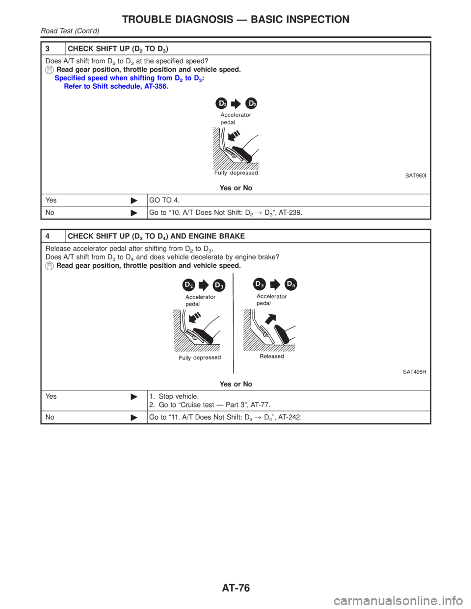
3 CHECK SHIFT UP (D2TO D3)
Does A/T shift from D2to D3at the specified speed?
Read gear position, throttle position and vehicle speed.
Specified speed when shifting from D
2to D3:
Refer to Shift schedule, AT-356.
SAT960I
YesorNo
Ye s©GO TO 4.
No©Go to ª10. A/T Does Not Shift: D
2,D3º, AT-239.
4 CHECK SHIFT UP (D3TO D4) AND ENGINE BRAKE
Release accelerator pedal after shifting from D2to D3.
Does A/T shift from D
3to D4and does vehicle decelerate by engine brake?
Read gear position, throttle position and vehicle speed.
SAT405H
YesorNo
Ye s©1. Stop vehicle.
2. Go to ªCruise test Ð Part 3º, AT-77.
No©Go to ª11. A/T Does Not Shift: D
3,D4º, AT-242.
TROUBLE DIAGNOSIS Ð BASIC INSPECTION
Road Test (Cont'd)
AT-76
Page 127 of 2395

Malfunction for P0731 exists.2,2,3,3
4,3,3,4
8) Make sure that ªOKº is displayed. (If ªNGº is displayed, refer
to ªDIAGNOSTIC PROCEDUREº.)
Refer to ªDIAGNOSTIC PROCEDUREº, AT-124.
Refer to shift schedule, AT-356.
With GST
Follow the procedure ªWith CONSULT-IIº.
DTC P0731 IMPROPER SHIFTING TO 1ST GEAR POSITION
Description (Cont'd)
AT-122