Page 1398 of 2395
DIAGNOSTIC PROCEDURE 8=NBEL0214S11[Lifting motor (front) check]
1 CHECK OUTPUT SIGNAL TO LIFTING MOTOR (FRONT)
Check voltage between seat control unit LH terminals 5 or 13 and ground.
SEL623W
OK or NG
OK©GO TO 2.
NG©Replace seat control unit LH.
2 CHECK LIFTING MOTOR (FRONT)
1. Disconnect front lifting device LH connector.
2. Apply 12V DC direct current to motor and check operation.
SEL624WA
OK or NG
OK©Check harness for operation between seat control unit LH and lifting motor (front).
NG©Replace lifting motor (front).
GI
MA
EM
LC
EC
FE
AT
TF
PD
AX
SU
BR
ST
RS
BT
HA
SC
IDX
AUTOMATIC DRIVE POSITIONER
Trouble Diagnoses (Cont'd)
EL-213
Page 1400 of 2395
DIAGNOSTIC PROCEDURE 10=NBEL0214S13(Power seat switch check)
1 CHECK POWER SEAT SWITCH
1. Disconnect power seat switch LH connector.
2. Check continuity between power seat switch terminals.
SEL569X
OK or NG
OK©Check the following.
IGround circuit for power seat switch
IHarness for open or short between seat control unit LH and power seat switch
NG©Replace power seat switch.
GI
MA
EM
LC
EC
FE
AT
TF
PD
AX
SU
BR
ST
RS
BT
HA
SC
IDX
AUTOMATIC DRIVE POSITIONER
Trouble Diagnoses (Cont'd)
EL-215
Page 1402 of 2395
DIAGNOSTIC PROCEDURE 12=NBEL0214S15(Key, detention, door switch and vehicle speed sensor check)
1 CHECK KEY SWITCH INPUT SIGNAL
Check voltage between seat control unit LH terminal 2 and ground.
SEL629W
OK or NG
OK©GO TO 2.
NG©Check the following.
I7.5A fuse [No. 24, located in fuse block (J/B)]
IKey switch
IHarness for open or short between key switch and fuse
IHarness for open or short between seat control unit LH and key switch
2 CHECK IGNITION SWITCH INPUT SIGNAL (ON AND START)
Check voltage between seat control unit LH terminals and ground.
SEL630W
OK or NG
OK©GO TO 3.
NG©Check the following.
I7.5A fuse [No. 11, located in fuse block (J/B)]
I7.5A fuse [No. 26, located in fuse block (J/B)]
IHarness for open or short between seat control unit LH and fuse
GI
MA
EM
LC
EC
FE
AT
TF
PD
AX
SU
BR
ST
RS
BT
HA
SC
IDX
AUTOMATIC DRIVE POSITIONER
Trouble Diagnoses (Cont'd)
EL-217
Page 1404 of 2395
6 CHECK VEHICLE SPEED SENSOR PULL UP VOLTAGE
1. Turn ignition switch ªONº.
2. Check voltage between seat control unit LH terminal 32 and ground.
SEL633W
OK or NG
OK©Harness for open or short between seat control unit LH and combination meter.
NG©Repair harness.
GI
MA
EM
LC
EC
FE
AT
TF
PD
AX
SU
BR
ST
RS
BT
HA
SC
IDX
AUTOMATIC DRIVE POSITIONER
Trouble Diagnoses (Cont'd)
EL-219
Page 1406 of 2395
Component Parts and Harness Connector
Location
NBEL0094
SEL362X
GI
MA
EM
LC
EC
FE
AT
TF
PD
AX
SU
BR
ST
RS
BT
HA
SC
IDX
AUTOMATIC SPEED CONTROL DEVICE (ASCD)
Component Parts and Harness Connector Location
EL-221
Page 1408 of 2395

IA/T shift solenoid valve A
Coast OperationNBEL0216S0204When the SET/COAST switch is depressed during cruise control driving, ASCD actuator returns the throttle
cable to decrease vehicle set speed until the switch is released. And then ASCD will keep the new set speed.
Accel OperationNBEL0216S0205When the RESUME/ACCEL switch is depressed, power is supplied
Ifrom ASCD steering switch terminal 3
Ito ASCD control unit terminal 24.
If the RESUME/ACCEL switch is depressed during cruise control driving, ASCD actuator pulls the throttle cable
to increase the vehicle speed until the switch is released or vehicle speed is reached to maximum controlled
speed by the system. And then ASCD will keep the new set speed.
Cancel OperationNBEL0216S0206When any of following condition exists, cruise operation will be canceled.
ICANCEL switch is depressed. (Power supply to ASCD control unit terminals 11 and 24)
IBrake pedal is depressed. (Power supply to ASCD control unit terminal 23 from stop lamp switch)
IBrake pedal is depressed or A/T selector lever is shifted to P or N position. (Power supply to ASCD con-
trol unit terminal 8 is interrupted.)
If MAIN switch is turned to OFF during ASCD is activated, all of ASCD operation will be canceled and vehicle
speed memory will be erased.
Resume OperationNBEL0216S0207When the RESUME/ACCEL switch is depressed after cancel operation other than depressing MAIN switch is
performed, vehicle speed will return to last set speed. To resume vehicle set speed, vehicle condition must
meet following conditions.
IBrake pedal is released.
IA/T selector lever is in other than P and N position.
IVehicle speed is between 40 km/h (25 MPH) and 144 km/h (89 MPH).
ASCD PUMP OPERATIONNBEL0216S03The ASCD pump consists of a vacuum motor, an air valve and a release valve. When the ASCD activates,
power is supplied
Ifrom terminal 12 of ASCD control unit
Ito ASCD pump terminal 1.
Ground is supplied to vacuum motor, air valve and release valve from ASCD control unit depending on the
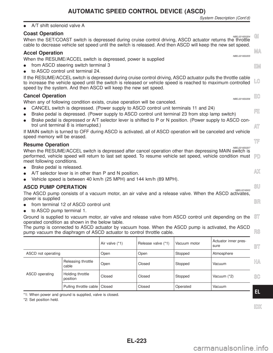
operated condition as shown in the below table.
The pump is connected to ASCD actuator by vacuum hose. When the ASCD pump is activated, the ASCD
pump vacuum the diaphragm of ASCD actuator to control throttle cable.
Air valve (*1) Release valve (*1) Vacuum motorActuator inner pres-
sure
ASCD not operating Open Open Stopped Atmosphere
ASCD operatingReleasing throttle
cableOpen Closed Stopped Vacuum
Holding throttle
positionClosed Closed Stopped Vacuum (*2)
Pulling throttle cable Closed Closed Operated Vacuum
*1: When power and ground is supplied, valve is closed.
*2: Set position held.
GI
MA
EM
LC
EC
FE
AT
TF
PD
AX
SU
BR
ST
RS
BT
HA
SC
IDX
AUTOMATIC SPEED CONTROL DEVICE (ASCD)
System Description (Cont'd)
EL-223
Page 1410 of 2395
Wiring Diagram Ð ASCD ÐNBEL0097FIG. 1NBEL0097S01
MEL838L
GI
MA
EM
LC
EC
FE
AT
TF
PD
AX
SU
BR
ST
RS
BT
HA
SC
IDX
AUTOMATIC SPEED CONTROL DEVICE (ASCD)
Wiring Diagram Ð ASCD Ð
EL-225
Page 1412 of 2395
FIG. 3NBEL0097S03
MEL840L
GI
MA
EM
LC
EC
FE
AT
TF
PD
AX
SU
BR
ST
RS
BT
HA
SC
IDX
AUTOMATIC SPEED CONTROL DEVICE (ASCD)
Wiring Diagram Ð ASCD Ð (Cont'd)
EL-227