2001 INFINITI QX4 height
[x] Cancel search: heightPage 1992 of 2395
SLC904-A
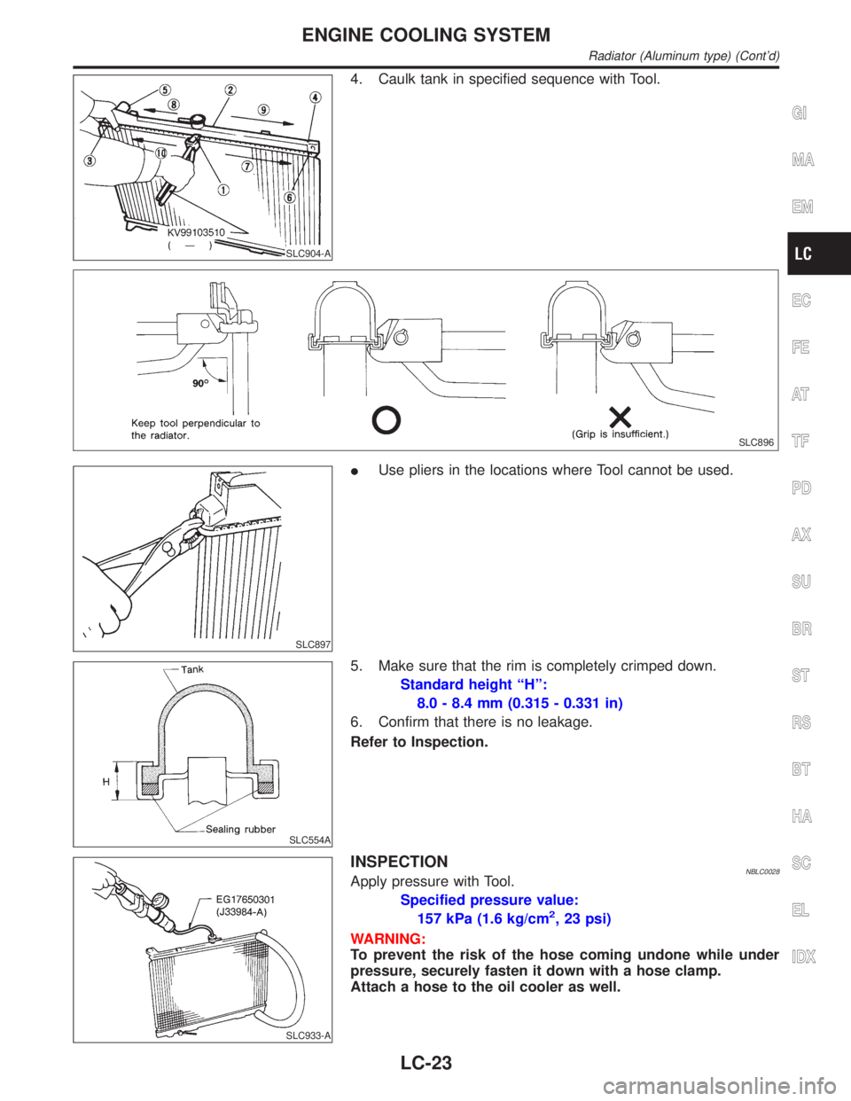
4. Caulk tank in specified sequence with Tool.
SLC896
SLC897
IUse pliers in the locations where Tool cannot be used.
SLC554A
5. Make sure that the rim is completely crimped down.
Standard height ªHº:
8.0 - 8.4 mm (0.315 - 0.331 in)
6. Confirm that there is no leakage.
Refer to Inspection.
SLC933-A
INSPECTIONNBLC0028Apply pressure with Tool.
Specified pressure value:
157 kPa (1.6 kg/cm
2, 23 psi)
WARNING:
To prevent the risk of the hose coming undone while under
pressure, securely fasten it down with a hose clamp.
Attach a hose to the oil cooler as well.
GI
MA
EM
EC
FE
AT
TF
PD
AX
SU
BR
ST
RS
BT
HA
SC
EL
IDX
ENGINE COOLING SYSTEM
Radiator (Aluminum type) (Cont'd)
LC-23
Page 2026 of 2395
PROPELLER SHAFT &
DIFFERENTIAL CARRIER
SECTION
PD
CONTENTS
PROPELLER SHAFT......................................................3
Noise, Vibration and Harshness (NVH)
Troubleshooting ...........................................................3
NVH TROUBLESHOOTING CHART............................3
Components.................................................................4
FRONT PROPELLER SHAFT.....................................4
REAR PROPELLER SHAFT.......................................5
On-vehicle Service.......................................................6
PROPELLER SHAFT VIBRATION...............................6
APPEARANCE CHECKING........................................6
Removal and Installation .............................................6
Inspection.....................................................................7
Disassembly.................................................................7
CENTER BEARING - 2WD -.......................................7
JOURNAL (71H AND 80B)..........................................8
Assembly .....................................................................9
CENTER BEARING - 2WD -.......................................9
JOURNAL (71H AND 80B)..........................................9
Service Data and Specifications (SDS)..................... 11
GENERAL SPECIFICATIONS................................... 11
SERVICE DATA....................................................... 11
SNAP RING (80B).................................................... 11
SNAP RING (71H)...................................................12
R200A
FRONT FINAL DRIVE...................................................13
Preparation ................................................................13
SPECIAL SERVICE TOOLS......................................13
Noise, Vibration and Harshness (NVH)
Troubleshooting .........................................................15
On-vehicle Service.....................................................15
FRONT OIL SEAL REPLACEMENT...........................15
REAR COVER GASKET REPLACEMENT..................16
Components...............................................................17
Removal and Installation ...........................................18
REMOVAL...............................................................18
INSTALLATION........................................................18
Disassembly...............................................................18
PRE-INSPECTION...................................................18
FINAL DRIVE HOUSING..........................................19
DIFFERENTIAL CASE..............................................21
DIFFERENTIAL SIDE SHAFT...................................22
Inspection...................................................................23
RING GEAR AND DRIVE PINION.............................23
DIFFERENTIAL CASE ASSEMBLY...........................23
BEARING................................................................23
Adjustment .................................................................24
SIDE BEARING PRELOAD.......................................24
PINION GEAR HEIGHT AND PINION BEARING
PRELOAD
...............................................................25
TOOTH CONTACT...................................................29
Assembly ...................................................................30
DIFFERENTIAL SIDE SHAFT...................................30
DIFFERENTIAL CASE..............................................31
FINAL DRIVE HOUSING..........................................32
Service Data and Specifications (SDS).....................36
R200A.....................................................................36
H233B
REAR FINAL DRIVE.....................................................38
Preparation ................................................................38
SPECIAL SERVICE TOOLS......................................38
Noise, Vibration and Harshness (NVH)
Troubleshooting .........................................................40
On-vehicle Service.....................................................40
FRONT OIL SEAL REPLACEMENT...........................40
Components...............................................................42
Removal and Installation ...........................................43
REMOVAL...............................................................43
INSTALLATION........................................................43
Disassembly...............................................................43
PRE-INSPECTION...................................................43
DIFFERENTIAL CARRIER........................................44
DIFFERENTIAL CASE..............................................46
Inspection...................................................................47
RING GEAR AND DRIVE PINION.............................47
DIFFERENTIAL CASE ASSEMBLY...........................47
BEARING................................................................47
Limited Slip Differential ..............................................47
PREPARATION FOR DISASSEMBLY........................47
GI
MA
EM
LC
EC
FE
AT
TF
AX
SU
BR
ST
RS
BT
HA
SC
EL
IDX
Page 2027 of 2395
DISASSEMBLY........................................................48
INSPECTION...........................................................49
ADJUSTMENT.........................................................50
ASSEMBLY.............................................................51
Adjustment .................................................................53
PINION GEAR HEIGHT............................................53
TOOTH CONTACT...................................................56Assembly ...................................................................57
DIFFERENTIAL CASE..............................................57
DIFFERENTIAL CARRIER........................................58
Service Data and Specifications (SDS).....................62
H233B.....................................................................62
CONTENTS(Cont'd)
PD-2
Page 2039 of 2395
Tool number
(Kent-Moore No.)
Tool nameDescription
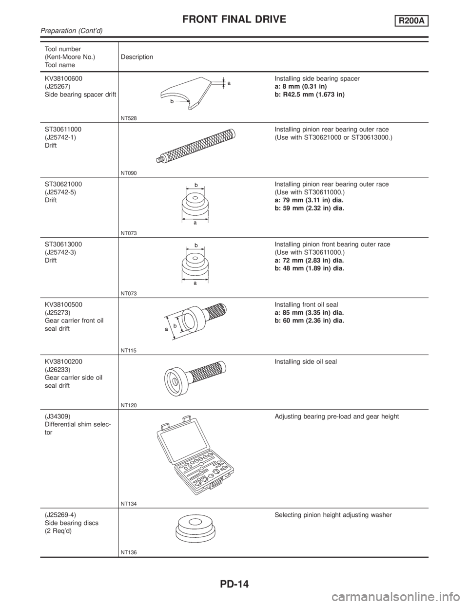
KV38100600
(J25267)
Side bearing spacer drift
NT528
Installing side bearing spacer
a: 8 mm (0.31 in)
b: R42.5 mm (1.673 in)
ST30611000
(J25742-1)
Drift
NT090
Installing pinion rear bearing outer race
(Use with ST30621000 or ST30613000.)
ST30621000
(J25742-5)
Drift
NT073
Installing pinion rear bearing outer race
(Use with ST30611000.)
a: 79 mm (3.11 in) dia.
b: 59 mm (2.32 in) dia.
ST30613000
(J25742-3)
Drift
NT073
Installing pinion front bearing outer race
(Use with ST30611000.)
a: 72 mm (2.83 in) dia.
b: 48 mm (1.89 in) dia.
KV38100500
(J25273)
Gear carrier front oil
seal drift
NT115
Installing front oil seal
a: 85 mm (3.35 in) dia.
b: 60 mm (2.36 in) dia.
KV38100200
(J26233)
Gear carrier side oil
seal drift
NT120
Installing side oil seal
(J34309)
Differential shim selec-
tor
NT134
Adjusting bearing pre-load and gear height
(J25269-4)
Side bearing discs
(2 Req'd)
NT136
Selecting pinion height adjusting washer
FRONT FINAL DRIVER200A
Preparation (Cont'd)
PD-14
Page 2046 of 2395
SPD670
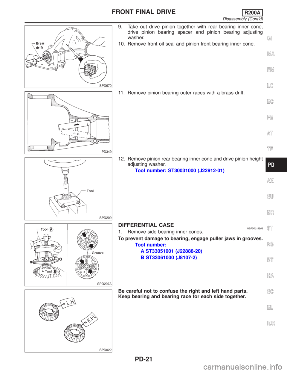
9. Take out drive pinion together with rear bearing inner cone,
drive pinion bearing spacer and pinion bearing adjusting
washer.
10. Remove front oil seal and pinion front bearing inner cone.
PD349
11. Remove pinion bearing outer races with a brass drift.
SPD209
12. Remove pinion rear bearing inner cone and drive pinion height
adjusting washer.
Tool number: ST30031000 (J22912-01)
SPD207A
DIFFERENTIAL CASENBPD0018S031. Remove side bearing inner cones.
To prevent damage to bearing, engage puller jaws in grooves.
Tool number:
A ST33051001 (J22888-20)
B ST33061000 (J8107-2)
SPD022
Be careful not to confuse the right and left hand parts.
Keep bearing and bearing race for each side together.
GI
MA
EM
LC
EC
FE
AT
TF
AX
SU
BR
ST
RS
BT
HA
SC
EL
IDX
FRONT FINAL DRIVER200A
Disassembly (Cont'd)
PD-21
Page 2049 of 2395
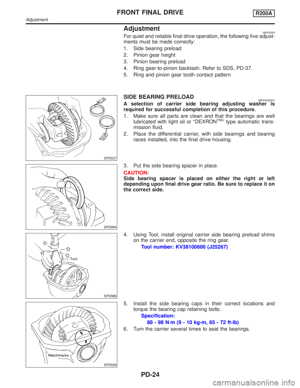
AdjustmentNBPD0020For quiet and reliable final drive operation, the following five adjust-
ments must be made correctly:
1. Side bearing preload
2. Pinion gear height
3. Pinion bearing preload
4. Ring gear-to-pinion backlash. Refer to SDS, PD-37.
5. Ring and pinion gear tooth contact pattern
SPD527
SIDE BEARING PRELOADNBPD0020S01A selection of carrier side bearing adjusting washer is
required for successful completion of this procedure.
1. Make sure all parts are clean and that the bearings are well
lubricated with light oil or ªDEXRON
TMº type automatic trans-
mission fluid.
2. Place the differential carrier, with side bearings and bearing
races installed, into the final drive housing.
SPD894
3. Put the side bearing spacer in place.
CAUTION:
Side bearing spacer is placed on either the right or left
depending upon final drive gear ratio. Be sure to replace it on
the correct side.
SPD986
4. Using Tool, install original carrier side bearing preload shims
on the carrier end, opposite the ring gear.
Tool number: KV38100600 (J25267)
SPD526
5. Install the side bearing caps in their correct locations and
torque the bearing cap retaining bolts.
Specification:
88 - 98 N´m (9 - 10 kg-m, 65 - 72 ft-lb)
6. Turn the carrier several times to seat the bearings.
FRONT FINAL DRIVER200A
Adjustment
PD-24
Page 2050 of 2395
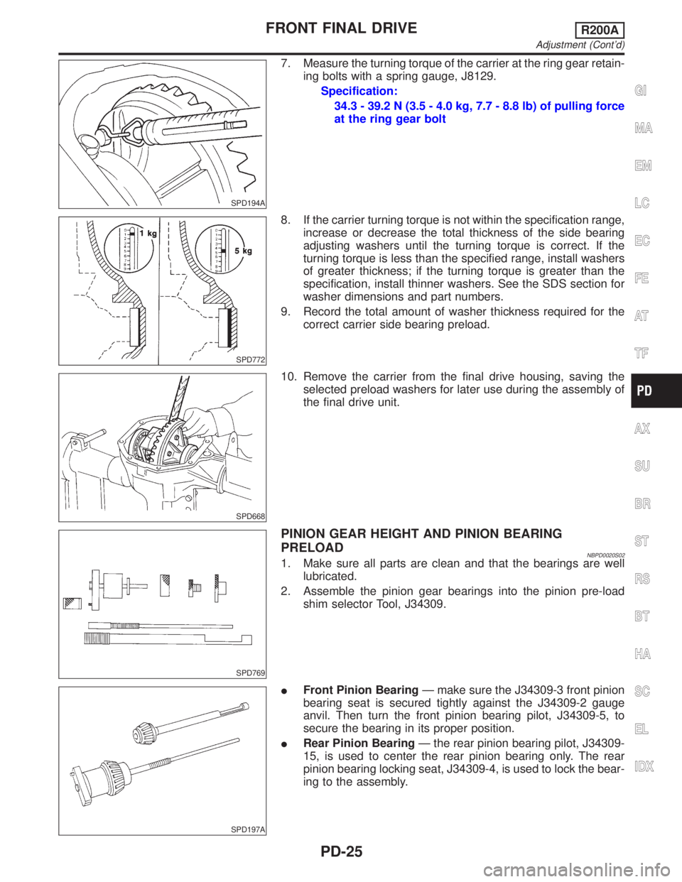
SPD194A
7. Measure the turning torque of the carrier at the ring gear retain-
ing bolts with a spring gauge, J8129.
Specification:
34.3 - 39.2 N (3.5 - 4.0 kg, 7.7 - 8.8 lb) of pulling force
at the ring gear bolt
SPD772
8. If the carrier turning torque is not within the specification range,
increase or decrease the total thickness of the side bearing
adjusting washers until the turning torque is correct. If the
turning torque is less than the specified range, install washers
of greater thickness; if the turning torque is greater than the
specification, install thinner washers. See the SDS section for
washer dimensions and part numbers.
9. Record the total amount of washer thickness required for the
correct carrier side bearing preload.
SPD668
10. Remove the carrier from the final drive housing, saving the
selected preload washers for later use during the assembly of
the final drive unit.
SPD769
PINION GEAR HEIGHT AND PINION BEARING
PRELOAD
NBPD0020S021. Make sure all parts are clean and that the bearings are well
lubricated.
2. Assemble the pinion gear bearings into the pinion pre-load
shim selector Tool, J34309.
SPD197A
IFront Pinion BearingÐ make sure the J34309-3 front pinion
bearing seat is secured tightly against the J34309-2 gauge
anvil. Then turn the front pinion bearing pilot, J34309-5, to
secure the bearing in its proper position.
IRear Pinion BearingÐ the rear pinion bearing pilot, J34309-
15, is used to center the rear pinion bearing only. The rear
pinion bearing locking seat, J34309-4, is used to lock the bear-
ing to the assembly.
GI
MA
EM
LC
EC
FE
AT
TF
AX
SU
BR
ST
RS
BT
HA
SC
EL
IDX
FRONT FINAL DRIVER200A
Adjustment (Cont'd)
PD-25
Page 2051 of 2395
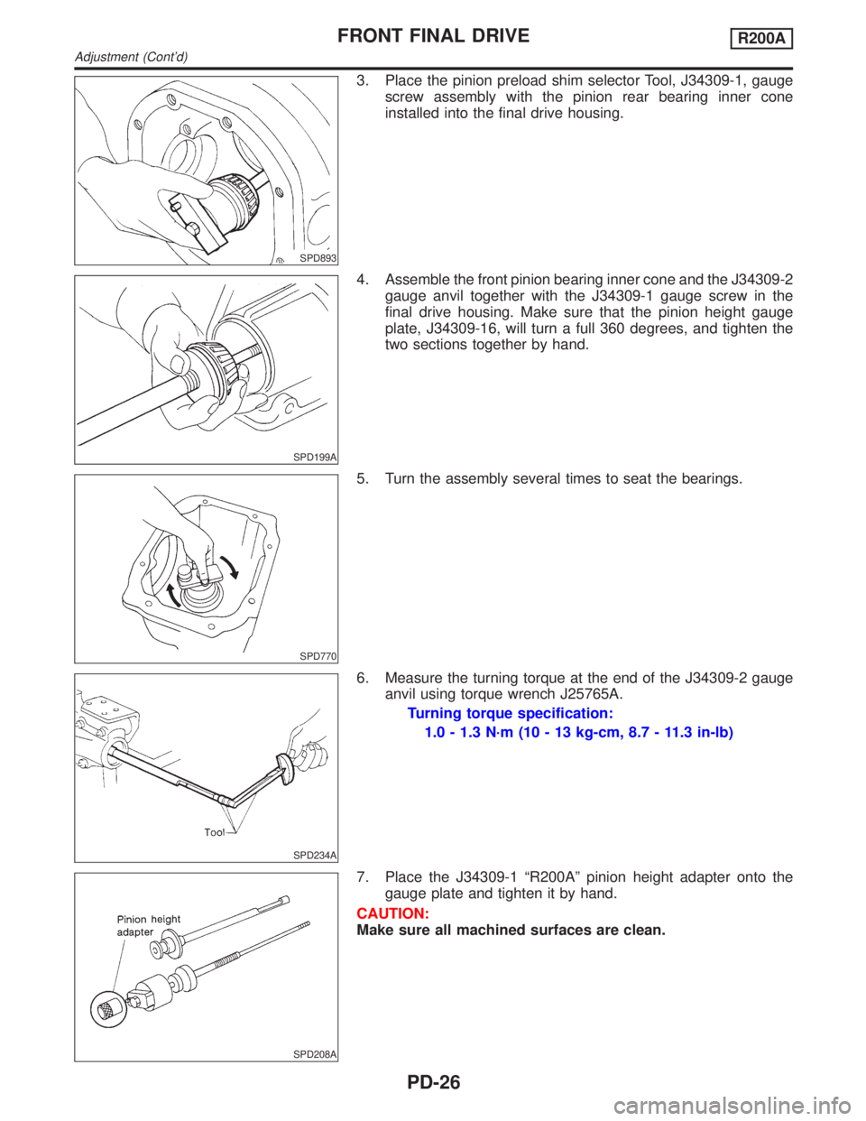
SPD893
3. Place the pinion preload shim selector Tool, J34309-1, gauge
screw assembly with the pinion rear bearing inner cone
installed into the final drive housing.
SPD199A
4. Assemble the front pinion bearing inner cone and the J34309-2
gauge anvil together with the J34309-1 gauge screw in the
final drive housing. Make sure that the pinion height gauge
plate, J34309-16, will turn a full 360 degrees, and tighten the
two sections together by hand.
SPD770
5. Turn the assembly several times to seat the bearings.
SPD234A
6. Measure the turning torque at the end of the J34309-2 gauge
anvil using torque wrench J25765A.
Turning torque specification:
1.0 - 1.3 N´m (10 - 13 kg-cm, 8.7 - 11.3 in-lb)
SPD208A
7. Place the J34309-1 ªR200Aº pinion height adapter onto the
gauge plate and tighten it by hand.
CAUTION:
Make sure all machined surfaces are clean.
FRONT FINAL DRIVER200A
Adjustment (Cont'd)
PD-26