Page 1294 of 2395
MEL005H
VEHICLE SPEED SENSOR SIGNAL CHECKNBEL0202S041. Remove vehicle speed sensor from transmission.
2. Turn vehicle speed sensor pinion quickly and measure voltage
across a and b.
GI
MA
EM
LC
EC
FE
AT
TF
PD
AX
SU
BR
ST
RS
BT
HA
SC
IDX
METERS AND GAUGES
Electrical Components Inspection (Cont'd)
EL-109
Page 1307 of 2395

SEL062WA
Fuel Warning Lamp Sensor CheckNBEL01661. Turn ignition switch ªOFFº.
2. Disconnect fuel level sensor unit harness connector B12.
3. Connect a resistor (80W) between fuel tank gauge unit harness
connector terminals 2 and 3.
4. Turn ignition switch ªONº.
The fuel warning lamp should come on.
NOTE:
ECM might store the 1st trip DTC P0180 during this inspection.
If the DTC is stored in ECM memory, erase the DTC after recon-
necting fuel tank gauge unit harness connector.
Refer to EC-60, ªHOW TO ERASE EMISSION-RELATED DIAG-
NOSTIC INFORMATIONº.
MEL425F
Electrical Components InspectionNBEL0051OIL PRESSURE SWITCH CHECKNBEL0051S02
Oil pressure
kPa (kg/cm2, psi)Continuity
Engine startMore than 10 - 20
(0.1-0.2,1-3)NO
Engine stopLess than 10 - 20
(0.1-0.2,1-3)YES
Check the continuity between the terminals of oil pressure switch
and body ground.
SEL901F
DIODE CHECKNBEL0051S03ICheck continuity using an ohmmeter.
IDiode is functioning properly if test results are as shown in the
figure at left.
ICheck diodes at the combination meter harness connector
instead of checking them on the combination meter assembly.
Refer to EL-115, ªWARNING LAMPº wiring diagrams.
NOTE:
Specification may vary depending on the type of tester. Before
performing this inspection, be sure to refer to the instruction
manual for the tester to be used.
WARNING LAMPS
Fuel Warning Lamp Sensor Check
EL-122
Page 1342 of 2395
5 CHECK SMART ENTRANCE CONTROL UNIT GROUND CIRCUIT
Check continuity between smart entrance control unit terminal 16 and ground.
SEL388X
OK or NG
OK©Replace smart entrance control unit.
NG©Repair harness or connectors.
SEC202B
Electrical Components InspectionNBEL0076REAR WINDOW DEFOGGER RELAYNBEL0076S01Check continuity between terminals 3 and 5, 6 and 7.
Condition Continuity
12V direct current supply between ter-
minals 1 and 2Ye s
No current supply No
SEL430TB
REAR WINDOW DEFOGGER SWITCHNBEL0076S02Check continuity between terminals when rear window defogger
switch is pushed and released.
Terminals Condition Continuity
1-2Rear window defogger
switch is pushedYe s
Rear window defogger
switch is releasedNo
SEL263
Filament CheckNBEL00771. Attach probe circuit tester (in volt range) to middle portion of
each filament.
GI
MA
EM
LC
EC
FE
AT
TF
PD
AX
SU
BR
ST
RS
BT
HA
SC
IDX
REAR WINDOW DEFOGGER
Trouble Diagnoses (Cont'd)
EL-157
Page 1358 of 2395

System DescriptionNBEL0206OUTLINENBEL0206S01Electric sunroof system consists of
ISunroof switch
ISunroof motor
IPower window relay
ISmart entrance control unit
Smart entrance control unit controls retained power operation.
OPERATIONNBEL0206S02The sunroof can be opened or closed and tilted up or down with the sunroof switch.
AUTO OPERATIONNBEL0206S03The power sunroof AUTO feature makes it possible to open and close the sunroof without holding the sunroof
switch in the down or up position.
RETAINED POWER OPERATIONNBEL0206S04When the ignition switch is turned to OFF position from ON or START position, power is supplied for 45 sec-
onds
Ito power window relay terminal 2
Ifrom smart entrance control unit terminal 5.
Ground is always supplied
Ito power window relay terminal 1
Ithrough body grounds.
When power and ground are supplied, power window relay continues to be energized, and the electrical sun-
roof can be operated.
The retained power operation is canceled when the driver or passenger side door is opened.
INTERRUPTION DETECTION FUNCTIONNBEL0206S05The CPU of sunroof motor monitors the sunroof motor operation and the sunroof position (full closed or other)
for sunroof by the signals from encoder and limit switch in sunroof motor.
When sunroof motor detects interruption during the following close operation,
Iautomatic close operation when ignition switch is in the ªONº position
Iautomatic close operation during retained power operation
sunroof switch controls the motor for open and the sunroof will operate about 150 mm (5.91 in).
GI
MA
EM
LC
EC
FE
AT
TF
PD
AX
SU
BR
ST
RS
BT
HA
SC
IDX
POWER SUNROOF
System Description
EL-173
Page 1418 of 2395

ASCD BRAKE/STOP LAMP SWITCH CHECK=NBEL0218S04
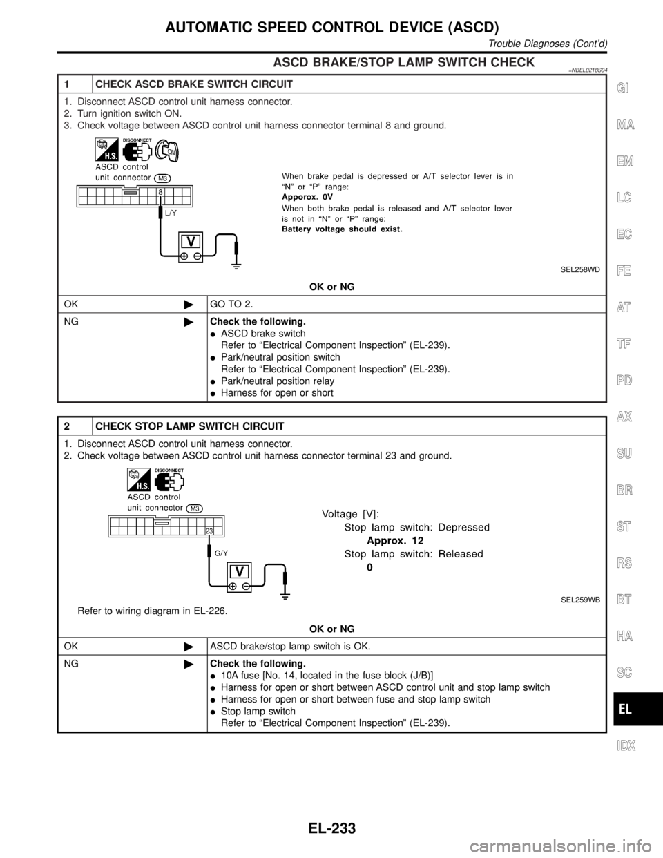
1 CHECK ASCD BRAKE SWITCH CIRCUIT
1. Disconnect ASCD control unit harness connector.
2. Turn ignition switch ON.
3. Check voltage between ASCD control unit harness connector terminal 8 and ground.
SEL258WD
OK or NG
OK©GO TO 2.
NG©Check the following.
IASCD brake switch
Refer to ªElectrical Component Inspectionº (EL-239).
IPark/neutral position switch
Refer to ªElectrical Component Inspectionº (EL-239).
IPark/neutral position relay
IHarness for open or short
2 CHECK STOP LAMP SWITCH CIRCUIT
1. Disconnect ASCD control unit harness connector.
2. Check voltage between ASCD control unit harness connector terminal 23 and ground.
SEL259WB
Refer to wiring diagram in EL-226.
OK or NG
OK©ASCD brake/stop lamp switch is OK.
NG©Check the following.
I10A fuse [No. 14, located in the fuse block (J/B)]
IHarness for open or short between ASCD control unit and stop lamp switch
IHarness for open or short between fuse and stop lamp switch
IStop lamp switch
Refer to ªElectrical Component Inspectionº (EL-239).
GI
MA
EM
LC
EC
FE
AT
TF
PD
AX
SU
BR
ST
RS
BT
HA
SC
IDX
AUTOMATIC SPEED CONTROL DEVICE (ASCD)
Trouble Diagnoses (Cont'd)
EL-233
Page 1424 of 2395
SEL302X
Electrical Component Inspection=NBEL0219ASCD BRAKE SWITCH AND STOP LAMP SWITCHNBEL0219S02
ConditionContinuity
ASCD brake
switchStop lamp switch
When brake pedal is depressed No Yes
When brake pedal is released Yes No
Check each switch after adjusting brake pedal Ð refer to BR-14,
ªBRAKE PEDAL AND BRACKETº.
SEL303X
PARK/NEUTRAL POSITION SWITCHNBEL0219S03
A/T selector lever positionContinuity
Between terminals 1 and 2
ªPº Yes
ªNº Yes
Except ªPº and ªNº No
GI
MA
EM
LC
EC
FE
AT
TF
PD
AX
SU
BR
ST
RS
BT
HA
SC
IDX
AUTOMATIC SPEED CONTROL DEVICE (ASCD)
Electrical Component Inspection
EL-239
Page 1539 of 2395

DATA TRANSMITTINGNBEL0180S05When contact to the Communicator Response Center is made,
vehicle sends electrical data including type of activation (i.e., emer-
gency call or alarm notification), vehicle location, time, etc.
SLEEP/WAKE UP CONTROLNBEL0180S063 minutes after the ignition switch is turned OFF, the system goes
into the SLEEP MODE to save battery power supply. Communica-
tion with Communicator Response Center is not available in the
SLEEP MODE.
To wake up the system, perform either of the following operations.
ITurn Ignition switch ON.
IPull back door outside handle for more than 10 seconds.
(Operation for door unlock function)
SEL532V
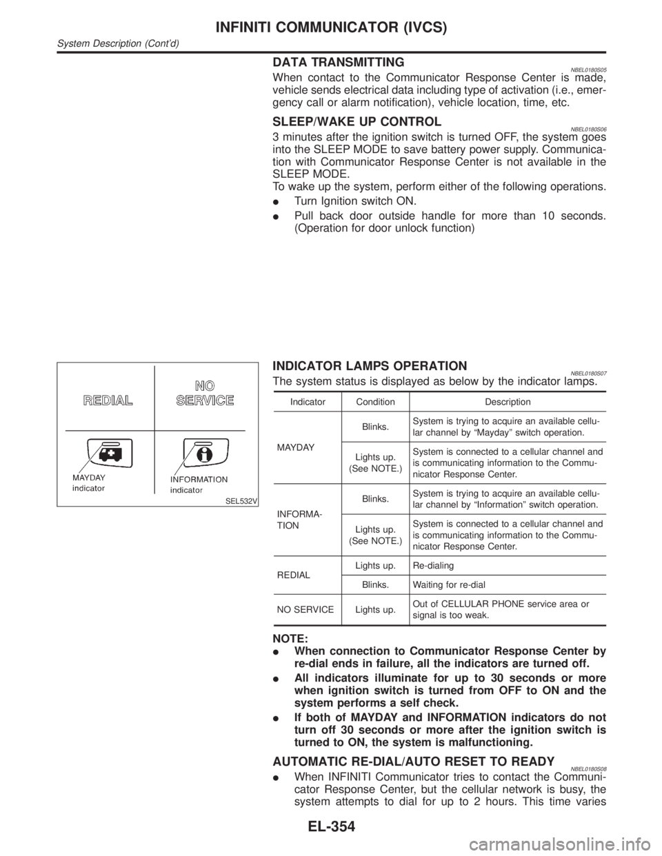
INDICATOR LAMPS OPERATIONNBEL0180S07The system status is displayed as below by the indicator lamps.
Indicator Condition Description
MAYDAYBlinks.System is trying to acquire an available cellu-
lar channel by ªMaydayº switch operation.
Lights up.
(See NOTE.)System is connected to a cellular channel and
is communicating information to the Commu-
nicator Response Center.
INFORMA-
TIONBlinks.System is trying to acquire an available cellu-
lar channel by ªInformationº switch operation.
Lights up.
(See NOTE.)System is connected to a cellular channel and
is communicating information to the Commu-
nicator Response Center.
REDIALLights up. Re-dialing
Blinks. Waiting for re-dial
NO SERVICE Lights up.Out of CELLULAR PHONE service area or
signal is too weak.
NOTE:
IWhen connection to Communicator Response Center by
re-dial ends in failure, all the indicators are turned off.
IAll indicators illuminate for up to 30 seconds or more
when ignition switch is turned from OFF to ON and the
system performs a self check.
IIf both of MAYDAY and INFORMATION indicators do not
turn off 30 seconds or more after the ignition switch is
turned to ON, the system is malfunctioning.
AUTOMATIC RE-DIAL/AUTO RESET TO READYNBEL0180S08IWhen INFINITI Communicator tries to contact the Communi-
cator Response Center, but the cellular network is busy, the
system attempts to dial for up to 2 hours. This time varies
INFINITI COMMUNICATOR (IVCS)
System Description (Cont'd)
EL-354
Page 1621 of 2395
Engine CompartmentNBEL0129
MEL134M
ELECTRICAL UNITS LOCATION
Engine Compartment
EL-436