2001 INFINITI QX4 ignition
[x] Cancel search: ignitionPage 1402 of 2395
DIAGNOSTIC PROCEDURE 12=NBEL0214S15(Key, detention, door switch and vehicle speed sensor check)
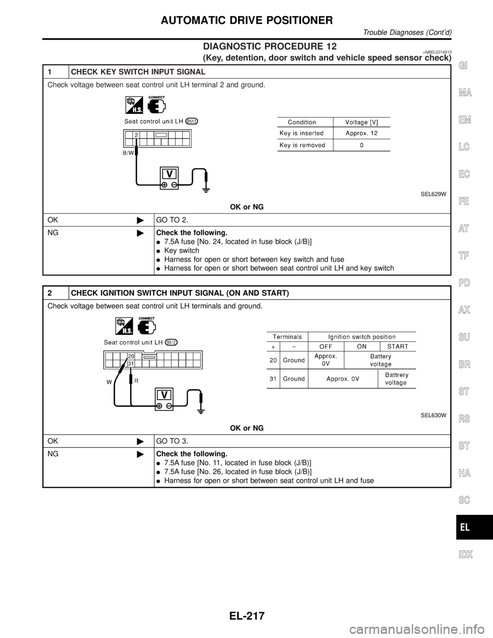
1 CHECK KEY SWITCH INPUT SIGNAL
Check voltage between seat control unit LH terminal 2 and ground.
SEL629W
OK or NG
OK©GO TO 2.
NG©Check the following.
I7.5A fuse [No. 24, located in fuse block (J/B)]
IKey switch
IHarness for open or short between key switch and fuse
IHarness for open or short between seat control unit LH and key switch
2 CHECK IGNITION SWITCH INPUT SIGNAL (ON AND START)
Check voltage between seat control unit LH terminals and ground.
SEL630W
OK or NG
OK©GO TO 3.
NG©Check the following.
I7.5A fuse [No. 11, located in fuse block (J/B)]
I7.5A fuse [No. 26, located in fuse block (J/B)]
IHarness for open or short between seat control unit LH and fuse
GI
MA
EM
LC
EC
FE
AT
TF
PD
AX
SU
BR
ST
RS
BT
HA
SC
IDX
AUTOMATIC DRIVE POSITIONER
Trouble Diagnoses (Cont'd)
EL-217
Page 1404 of 2395
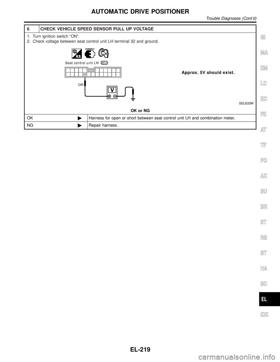
6 CHECK VEHICLE SPEED SENSOR PULL UP VOLTAGE
1. Turn ignition switch ªONº.
2. Check voltage between seat control unit LH terminal 32 and ground.
SEL633W
OK or NG
OK©Harness for open or short between seat control unit LH and combination meter.
NG©Repair harness.
GI
MA
EM
LC
EC
FE
AT
TF
PD
AX
SU
BR
ST
RS
BT
HA
SC
IDX
AUTOMATIC DRIVE POSITIONER
Trouble Diagnoses (Cont'd)
EL-219
Page 1407 of 2395
System DescriptionNBEL0216Refer to Owner's Manual for ASCD operating instructions.
POWER SUPPLY AND GROUNDNBEL0216S01Power is supplied at all times:
Ithrough 10A fuse [No. 14, located in the fuse block (J/B)]
Ito the stop lamp switch terminal 1, and
Ithrough 7.5A fuse (No. 52, located in fuse and fusible link box)
Ito the horn relay terminals 1 and 3.
When ignition switch is in the ON or START position, power is supplied:
Ithrough 7.5A fuse [No. 11, located in the fuse block (J/B)]
Ito ASCD brake switch terminal 1 and
Ito ASCD control unit terminal 5,
Ithrough 10A fuse [No. 18, located in the fuse block (J/B)]
Ito park/neutral position relay terminal 1,
Ithrough 10A fuse [No. 8, located in the fuse block (J/B)]
Ito combination meter terminal 66, and
When park/neutral position switch is in the P or N position, ground is supplied:
Ito park/neutral position relay terminal 2
Ithrough park/neutral position switch and body grounds B55 and B75.
When ASCD main switch is depressed (ON), ground is supplied:
Ito ASCD control unit terminal 9
Ifrom ASCD steering switch terminal 4
Ito ASCD steering switch terminal 5
Ithrough body grounds M4, M66 and M147
then ASCD control unit holds CRUISE condition and illuminates CRUISE indicator.
Ground is supplied:
Ifrom ASCD control unit terminal 15
Ito combination meter terminal 46.
OPERATIONNBEL0216S02Set OperationNBEL0216S0201To activate the ASCD, all following conditions must exist.
IGround supply to ASCD control unit terminal 9 (Main switch is in ON position.)
IPower supply to ASCD control unit terminal 8 (Brake pedal is released and A/T selector lever is in other
than P and N position.)
IVehicle speed is between 40 km/h (25 MPH) and 144 km/h (89 MPH). (Signal from combination meter)
When the SET/COAST switch is depressed, power is supplied:
Ifrom ASCD steering switch terminal 2
Ito ASCD control unit terminal 11.
And then ASCD pump is activated to control throttle wire and ASCD control unit supply ground
Ito combination meter terminals 51 to illuminate SET indicator.
A/T Overdrive Control during Cruise Control DrivingNBEL0216S0202When the vehicle speed is approximately 3 km/h (2 MPH) below set speed, a signal is sent
Ifrom ASCD control unit terminal 10
Ito TCM (transmission control module) terminal 24.
When this occurs, the TCM (transmission control module) cancels overdrive.
After vehicle speed is approximately 1 km/h (1 MPH) below set speed, overdrive is reactivated.
ASCD Shifting ControlNBEL0216S0203During ASCD cruise, ASCD control unit controls A/T shifting to avoid uncomfortable shifting.
This is used to control the signals below.
IThrottle position sensor from ECM
AUTOMATIC SPEED CONTROL DEVICE (ASCD)
System Description
EL-222
Page 1416 of 2395
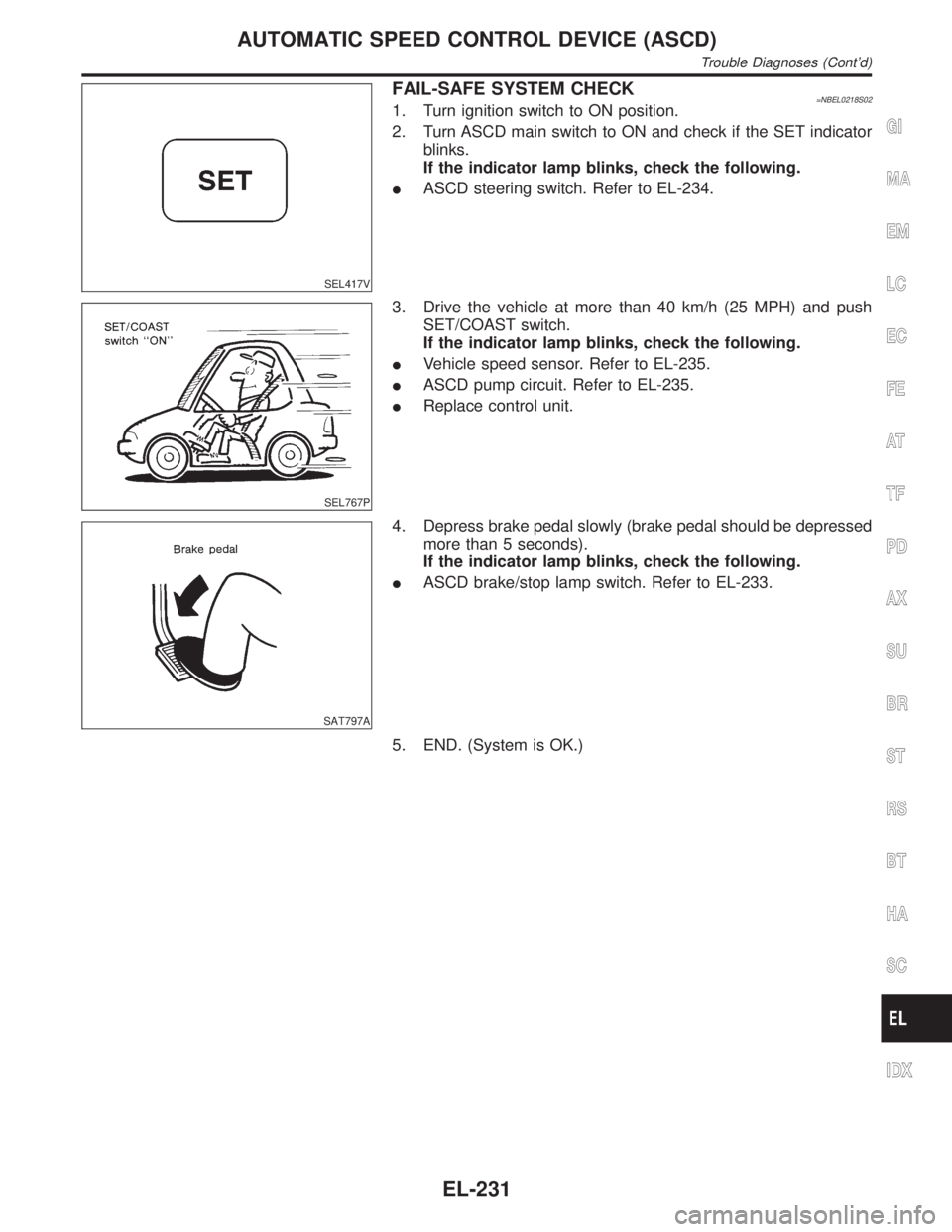
SEL417V
FAIL-SAFE SYSTEM CHECK=NBEL0218S021. Turn ignition switch to ON position.
2. Turn ASCD main switch to ON and check if the SET indicator
blinks.
If the indicator lamp blinks, check the following.
IASCD steering switch. Refer to EL-234.
SEL767P
3. Drive the vehicle at more than 40 km/h (25 MPH) and push
SET/COAST switch.
If the indicator lamp blinks, check the following.
IVehicle speed sensor. Refer to EL-235.
IASCD pump circuit. Refer to EL-235.
IReplace control unit.
SAT797A
4. Depress brake pedal slowly (brake pedal should be depressed
more than 5 seconds).
If the indicator lamp blinks, check the following.
IASCD brake/stop lamp switch. Refer to EL-233.
5. END. (System is OK.)
GI
MA
EM
LC
EC
FE
AT
TF
PD
AX
SU
BR
ST
RS
BT
HA
SC
IDX
AUTOMATIC SPEED CONTROL DEVICE (ASCD)
Trouble Diagnoses (Cont'd)
EL-231
Page 1417 of 2395
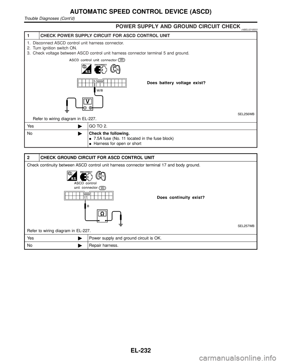
POWER SUPPLY AND GROUND CIRCUIT CHECK=NBEL0218S03
1 CHECK POWER SUPPLY CIRCUIT FOR ASCD CONTROL UNIT
1. Disconnect ASCD control unit harness connector.
2. Turn ignition switch ON.
3. Check voltage between ASCD control unit harness connector terminal 5 and ground.
SEL256WB
Refer to wiring diagram in EL-227.
Ye s©GO TO 2.
No©Check the following.
I7.5A fuse (No. 11 located in the fuse block)
IHarness for open or short
2 CHECK GROUND CIRCUIT FOR ASCD CONTROL UNIT
Check continuity between ASCD control unit harness connector terminal 17 and body ground.
SEL257WB
Refer to wiring diagram in EL-227.
Ye s©Power supply and ground circuit is OK.
No©Repair harness.
AUTOMATIC SPEED CONTROL DEVICE (ASCD)
Trouble Diagnoses (Cont'd)
EL-232
Page 1418 of 2395
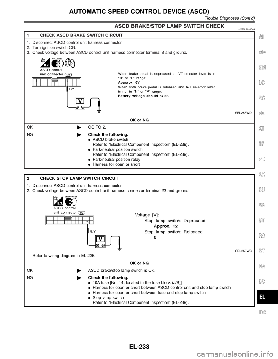
ASCD BRAKE/STOP LAMP SWITCH CHECK=NBEL0218S04
1 CHECK ASCD BRAKE SWITCH CIRCUIT
1. Disconnect ASCD control unit harness connector.
2. Turn ignition switch ON.
3. Check voltage between ASCD control unit harness connector terminal 8 and ground.
SEL258WD
OK or NG
OK©GO TO 2.
NG©Check the following.
IASCD brake switch
Refer to ªElectrical Component Inspectionº (EL-239).
IPark/neutral position switch
Refer to ªElectrical Component Inspectionº (EL-239).
IPark/neutral position relay
IHarness for open or short
2 CHECK STOP LAMP SWITCH CIRCUIT
1. Disconnect ASCD control unit harness connector.
2. Check voltage between ASCD control unit harness connector terminal 23 and ground.
SEL259WB
Refer to wiring diagram in EL-226.
OK or NG
OK©ASCD brake/stop lamp switch is OK.
NG©Check the following.
I10A fuse [No. 14, located in the fuse block (J/B)]
IHarness for open or short between ASCD control unit and stop lamp switch
IHarness for open or short between fuse and stop lamp switch
IStop lamp switch
Refer to ªElectrical Component Inspectionº (EL-239).
GI
MA
EM
LC
EC
FE
AT
TF
PD
AX
SU
BR
ST
RS
BT
HA
SC
IDX
AUTOMATIC SPEED CONTROL DEVICE (ASCD)
Trouble Diagnoses (Cont'd)
EL-233
Page 1426 of 2395
System DescriptionNBEL0102Power is supplied at all times
Ifrom 40A fusible link (letterf, located in the fuse and fusible link box)
Ito circuit breaker terminal 1
Ithrough circuit breaker terminal 2
Ito power window relay terminal 3,
Ito front power window main switch terminal 4, and
Ito front power window switch RH terminal 6.
With ignition switch in ON or START position, power is supplied
Ithrough 7.5A fuse [No. 11, located in the fuse block (J/B)]
Ito power window relay terminal 2, and
Ito smart entrance control unit terminal 33.
Ground is supplied to power window relay terminal 1
Ithrough body grounds M4, M66 and M147.
The power window relay is energized and power is supplied
Ithrough power window relay terminal 5
Ito front power window main switch terminal 11,
Ito front power window switch RH terminal 13,
Ito rear power window switch LH and RH terminals 5.
MANUAL OPERATIONNBEL0102S01Front Door LHNBEL0102S0101Ground is supplied
Ito front power window main switch terminal 5
Ithrough body grounds M77 and M111.
WINDOW UP
When the front LH switch in the front power window main switch is pressed in the up position, power is sup-
plied
Ito front power window regulator LH terminal 1
Ithrough front power window main switch terminal 2.
Ground is supplied
Ito front power window regulator LH terminal 3
Ithrough front power window main switch terminal 3.
Then, the motor raises the window until the switch is released.
WINDOW DOWN
When the LH switch in the front power window main switch is pressed in the down position, power is supplied
Ito front power window regulator LH terminal 3
Ithrough front power window main switch terminal 3.
Ground is supplied
Ito front power window regulator LH terminal 1
Ithrough front power window main switch terminal 2.
Then, the motor lowers the window until the switch is released.
Front Door RHNBEL0102S0102Ground is supplied
Ito front power window main switch terminal 5
Ithrough body grounds M77 and M111.
NOTE:
Numbers in parentheses are terminal numbers, when power window switch is pressed in the UP and DOWN
positions respectively.
FRONT POWER WINDOW MAIN SWITCH OPERATION
When front RH switch in the front power window main switch is pressed UP or DOWN, a signal is supplied
Ithrough front power window main switch terminal 8
GI
MA
EM
LC
EC
FE
AT
TF
PD
AX
SU
BR
ST
RS
BT
HA
SC
IDX
POWER WINDOW
System Description
EL-241
Page 1427 of 2395
Ito front power window switch RH terminal 11.
The subsequent operation is the same as the front power window switch RH operation.
FRONT POWER WINDOW SWITCH RH OPERATION
Power is supplied
Ithrough front power window switch RH (5, 4)
Ito front power window regulator RH (1, 3).
Ground is supplied
Ito front power window regulator RH (3, 1)
Ithrough front power window switch RH (4, 5)
Ito front power window switch RH terminal 12
Ithrough front power window main switch terminal 1.
Then, the motor raises or lowers the window until the switch is released.
Rear Door LHNBEL0102S0104Ground is supplied
Ito front power window main switch terminal 5
Ithrough body grounds the M77 and M111.
NOTE:
Numbers in parentheses are terminal numbers, when the power window switch is pressed in the UP and
DOWN positions.
FRONT POWER WINDOW MAIN SWITCH OPERATION
Power is supplied
Ithrough front power window main switch terminal (13, 12)
Ito rear power window switch LH terminal (3, 4)
The subsequent operation is the same as the rear power window switch LH operation.
REAR POWER WINDOW SWITCH LH
Power is supplied
Ithrough rear power window switch LH (1, 2)
Ito rear power window regulator LH (1, 2)
Ground is supplied
Ito rear power window regulator LH (2, 1)
Ithrough rear power window switch LH (2, 1)
Ito rear power window switch LH terminal (4, 3)
Ithrough front power window main switch terminal (12, 13)
Then, the motor raises or lowers the window until the switch is released.
Rear Door RHNBEL0102S0105Rear door RH windows will rise and lower in the same manner as the rear door LH window.
AUTO OPERATIONNBEL0102S02The power window AUTO feature enables the driver or front passenger to open or close the driver's and front
passenger's window without holding the window switch in the up or down position.
The AUTO feature only operates on the driver's and front passenger's window upward and downward move-
ment.
POWER WINDOW LOCKNBEL0102S03The power window lock is designed to lock operation of all windows except for driver's door window.
When the lock switch is pressed to lock position, the ground of the front and rear power window switches, in
the power window main switch, is disconnected. This prevents the power window motors from operating.
RETAINED POWER OPERATIONNBEL0102S04When the ignition switch is turned to OFF position from ON or START position, power is supplied for 45 sec-
onds
Ito power window relay terminal 2
Ifrom smart entrance control unit terminal 5.
Ground is always supplied
POWER WINDOW
System Description (Cont'd)
EL-242