Page 1345 of 2395
![INFINITI QX4 2001 Factory Service Manual System DescriptionNBEL0079Refer to Owners Manual for audio system operating instructions.
Power is supplied at all times
Ithrough 15A fuse [No. 4, located in the fuse block (J/B)]
Ito audio unit term INFINITI QX4 2001 Factory Service Manual System DescriptionNBEL0079Refer to Owners Manual for audio system operating instructions.
Power is supplied at all times
Ithrough 15A fuse [No. 4, located in the fuse block (J/B)]
Ito audio unit term](/manual-img/42/57027/w960_57027-1344.png)
System DescriptionNBEL0079Refer to Owner's Manual for audio system operating instructions.
Power is supplied at all times
Ithrough 15A fuse [No. 4, located in the fuse block (J/B)]
Ito audio unit terminal 6,
Ito audio amp. relay terminal 3 and
Ito rear speaker amp. terminal 11.
With the ignition switch in the ACC or ON position, power is supplied
Ithrough 10A fuse [No. 10, located in the fuse block (J/B)]
Ito audio unit terminal 10.
Ground is supplied through the case of the audio unit.
Ground is supplied
Ito audio amp. relay terminal 2
Ithrough body grounds M4, M66 and M147
Ito front door speaker LH terminal 5 and
Ito front door speaker RH terminal 5
Ithrough body grounds M77 and M111
Ito rear speaker amp. terminal 24
Ithrough body grounds B11, B22 and D210.
When the audio unit POWER button is pressed, power is supplied
Ito rear speaker amp. terminal 9 and
Ito audio amp. relay terminal 1
Ifrom audio unit terminal 12.
Then audio amp. relay is energized and power is supplied
Ito front door speaker LH terminal 4 and
Ito front door speaker RH terminal 4.
Audio signals are supplied
Ithrough audio unit terminals 1, 2, 3, 4, 13, 14, 15 and 16
Ito terminals 2 and 6 of the LH and RH front speakers and terminals 5, 7, 18 and 20 of the rear speaker
amp.
Ito LH and RH tweeters through terminals 1 and 3 of the front speakers
Ito rear LH and RH speakers through terminals 1, 2, 25 and 26 of the rear speaker amp.
AUDIO
System Description
EL-160
Page 1351 of 2395

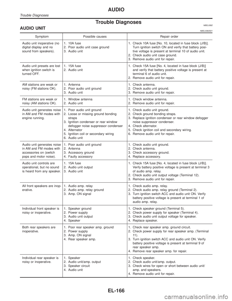
Trouble DiagnosesNBEL0082AUDIO UNITNBEL0082S01
Symptom Possible causes Repair order
Audio unit inoperative (no
digital display and no
sound from speakers).1. 10A fuse
2. Poor audio unit case ground
3. Audio unit1. Check 10A fuse [No. 10, located in fuse block (J/B)].
Turn ignition switch ON and verify that battery posi-
tive voltage is present at terminal 10 of audio unit.
2. Check audio unit case ground.
3. Remove audio unit for repair.
Audio unit presets are lost
when ignition switch is
turned OFF.1. 15A fuse
2. Audio unit1. Check 15A fuse [No. 4, located in fuse block (J/B)]
and verify that battery positive voltage is present at
terminal 6 of audio unit.
2. Remove audio unit for repair.
AM stations are weak or
noisy (FM stations OK).1. Antenna
2. Poor audio unit ground
3. Audio unit1. Check antenna.
2. Check audio unit ground.
3. Remove audio unit for repair.
FM stations are weak or
noisy (AM stations OK).1. Window antenna
2. Audio unit1. Check window antenna.
2. Remove audio unit for repair.
Audio unit generates noise
in AM and FM modes with
engine running.1. Poor audio unit ground
2. Loose or missing ground bonding
straps
3. Ignition condenser or rear window
defogger noise suppressor condenser
4. Alternator
5. Ignition coil or secondary wiring
6. Audio unit1. Check audio unit ground.
2. Check ground bonding straps.
3. Replace ignition condenser or rear window defogger
noise suppressor condenser.
4. Check alternator.
5. Check ignition coil and secondary wiring.
6. Remove audio unit for repair.
Audio unit generates noise
in AM and FM modes with
accessories on (switch
pops and motor noise).1. Poor audio unit ground
2. Antenna
3. Accessory ground
4. Faulty accessory1. Check audio unit ground.
2. Check antenna.
3. Check accessory ground.
4. Replace accessory.
Audio unit controls are
operational, but no sound
is heard from any speaker.1. 15A fuse
2. Audio unit output
3. Audio unit1. Check 15A fuse [No. 4, located in fuse block (J/B)].
Verify battery positive voltage is present at terminal 3
of audio amp. relay.
2. Check audio unit output voltage (Terminal 12).
3. Remove audio unit for repair.
All front speakers are inop-
erative.1. Audio amp. relay
2. Audio amp. relay ground
3. Amp. ON signal1. Check audio amp. relay.
2. Check audio amp. relay ground (Terminal 2).
3. Turn ignition switch ACC and audio unit ON. Verify
battery positive voltage is present at terminal 1 of
audio amp. relay.
Individual front speaker is
noisy or inoperative.1. Speaker ground
2. Power supply
3. Audio unit output
4. Speaker1. Check speaker ground (Terminal 5).
2. Check power supply for speaker (Terminal 4).
3. Check audio unit output voltage for speaker.
4. Replace speaker.
Both rear speakers are
inoperative.1. Poor rear speaker amp. ground
2. Power supply
3. Amp. ON signal
4. Rear speaker amp.1. Check rear speaker amp. ground circuit.
2. Check power supply for rear speaker amp. (Terminal
11).
3. Turn ignition switch ACC and audio unit ON. Verify
battery positive voltage is present at terminal 9 of
rear speaker amp.
4. Remove rear speaker amp. for repair.
Individual rear speaker is
noisy or inoperative.1. Speaker
2. Audio unit/amp. output
3. Speaker circuit
4. Audio unit1. Check speaker.
2. Check audio unit/amp. output.
3. Check wires for open or short between audio unit/
amp. and speakers.
4. Remove audio unit for repair.
AUDIO
Trouble Diagnoses
EL-166
Page 1352 of 2395
InspectionNBEL0083AUDIO UNIT AND AMP.NBEL0083S01All voltage inspections are made with:
IIgnition switch ON or ACC
IAudio unit ON
IAudio unit and amps. connected (If audio unit or amp. is removed for inspection, supply a ground to the
case using a jumper wire.)
ANTENNANBEL0083S021. Using a jumper wire, clip an auxiliary ground between antenna and body.
IIf reception improves, check antenna ground (at body surface).
IIf reception does not improve, check main feeder cable for short circuit or open circuit.
GI
MA
EM
LC
EC
FE
AT
TF
PD
AX
SU
BR
ST
RS
BT
HA
SC
IDX
AUDIO
Inspection
EL-167
Page 1356 of 2395
Trouble DiagnosesNBEL0086POWER ANTENNANBEL0086S01
Symptom Possible causes Repair order
Power antenna does not
operate.1. 7.5A fuse
2. Audio unit signal
3. Grounds M4, M66 and M1471. Check 7.5A fuse [No. 24, located in fuse block (J/B)].
Verify that battery positive voltage is present at termi-
nal 6 of power antenna.
2. Turn ignition switch and audio unit ON. Verify that
battery positive voltage is present at terminal 4 of
power antenna.
3. Check grounds M4, M66 and M147.
Location of AntennaNBEL0087
YEL067K
MEL036G
Antenna Rod ReplacementNBEL0088REMOVALNBEL0088S011. Remove antenna nut and antenna base.
GI
MA
EM
LC
EC
FE
AT
TF
PD
AX
SU
BR
ST
RS
BT
HA
SC
IDX
AUDIO ANTENNA
Trouble Diagnoses
EL-171
Page 1358 of 2395

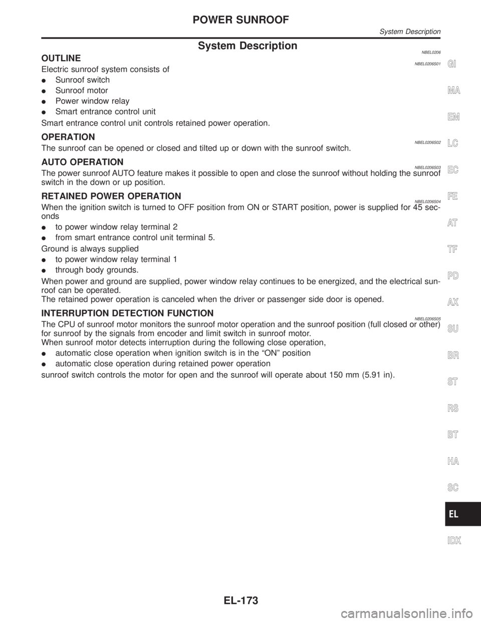
System DescriptionNBEL0206OUTLINENBEL0206S01Electric sunroof system consists of
ISunroof switch
ISunroof motor
IPower window relay
ISmart entrance control unit
Smart entrance control unit controls retained power operation.
OPERATIONNBEL0206S02The sunroof can be opened or closed and tilted up or down with the sunroof switch.
AUTO OPERATIONNBEL0206S03The power sunroof AUTO feature makes it possible to open and close the sunroof without holding the sunroof
switch in the down or up position.
RETAINED POWER OPERATIONNBEL0206S04When the ignition switch is turned to OFF position from ON or START position, power is supplied for 45 sec-
onds
Ito power window relay terminal 2
Ifrom smart entrance control unit terminal 5.
Ground is always supplied
Ito power window relay terminal 1
Ithrough body grounds.
When power and ground are supplied, power window relay continues to be energized, and the electrical sun-
roof can be operated.
The retained power operation is canceled when the driver or passenger side door is opened.
INTERRUPTION DETECTION FUNCTIONNBEL0206S05The CPU of sunroof motor monitors the sunroof motor operation and the sunroof position (full closed or other)
for sunroof by the signals from encoder and limit switch in sunroof motor.
When sunroof motor detects interruption during the following close operation,
Iautomatic close operation when ignition switch is in the ªONº position
Iautomatic close operation during retained power operation
sunroof switch controls the motor for open and the sunroof will operate about 150 mm (5.91 in).
GI
MA
EM
LC
EC
FE
AT
TF
PD
AX
SU
BR
ST
RS
BT
HA
SC
IDX
POWER SUNROOF
System Description
EL-173
Page 1372 of 2395

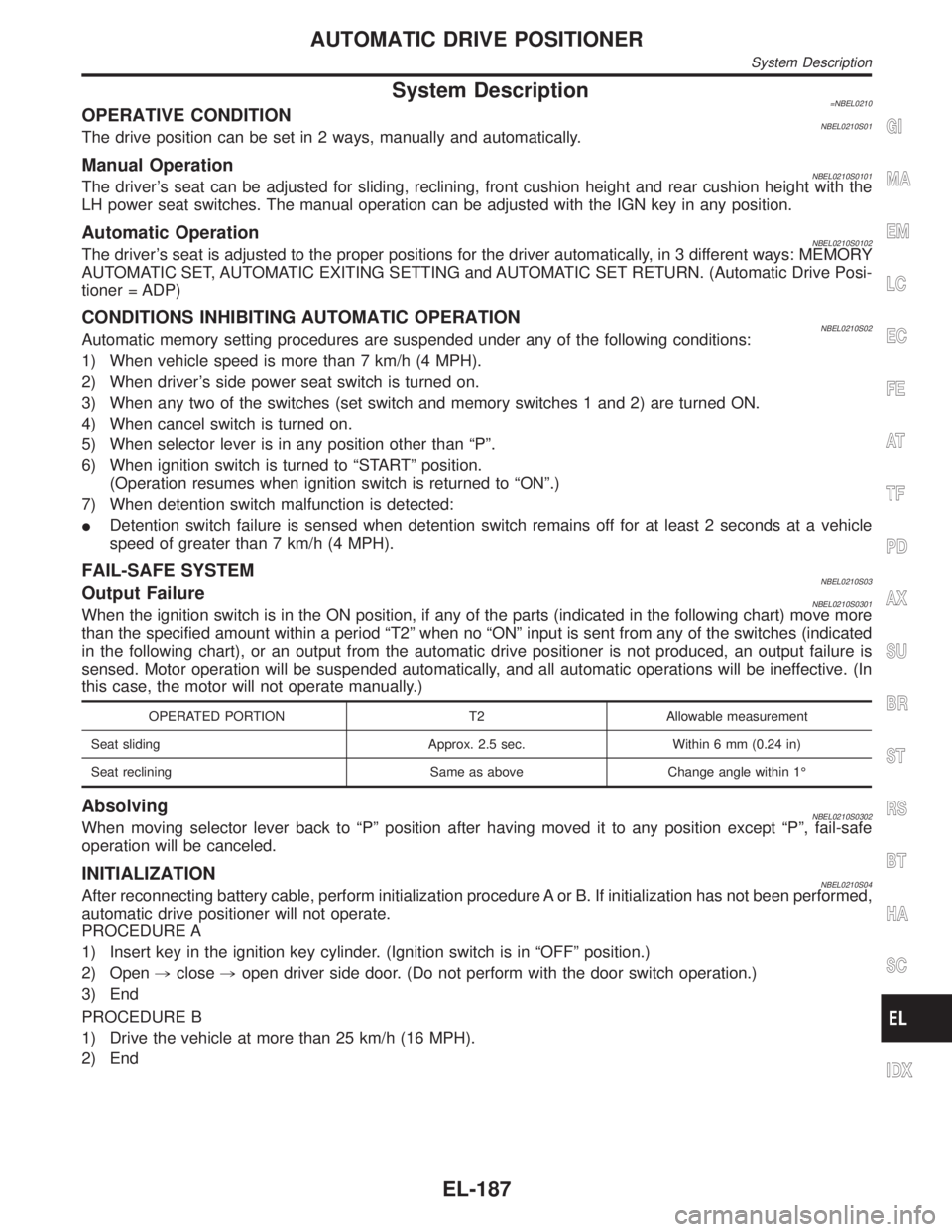
System Description=NBEL0210OPERATIVE CONDITIONNBEL0210S01The drive position can be set in 2 ways, manually and automatically.
Manual OperationNBEL0210S0101The driver's seat can be adjusted for sliding, reclining, front cushion height and rear cushion height with the
LH power seat switches. The manual operation can be adjusted with the IGN key in any position.
Automatic OperationNBEL0210S0102The driver's seat is adjusted to the proper positions for the driver automatically, in 3 different ways: MEMORY
AUTOMATIC SET, AUTOMATIC EXITING SETTING and AUTOMATIC SET RETURN. (Automatic Drive Posi-
tioner = ADP)
CONDITIONS INHIBITING AUTOMATIC OPERATIONNBEL0210S02Automatic memory setting procedures are suspended under any of the following conditions:
1) When vehicle speed is more than 7 km/h (4 MPH).
2) When driver's side power seat switch is turned on.
3) When any two of the switches (set switch and memory switches 1 and 2) are turned ON.
4) When cancel switch is turned on.
5) When selector lever is in any position other than ªPº.
6) When ignition switch is turned to ªSTARTº position.
(Operation resumes when ignition switch is returned to ªONº.)
7) When detention switch malfunction is detected:
IDetention switch failure is sensed when detention switch remains off for at least 2 seconds at a vehicle
speed of greater than 7 km/h (4 MPH).
FAIL-SAFE SYSTEMNBEL0210S03Output FailureNBEL0210S0301When the ignition switch is in the ON position, if any of the parts (indicated in the following chart) move more
than the specified amount within a period ªT2º when no ªONº input is sent from any of the switches (indicated
in the following chart), or an output from the automatic drive positioner is not produced, an output failure is
sensed. Motor operation will be suspended automatically, and all automatic operations will be ineffective. (In
this case, the motor will not operate manually.)
OPERATED PORTION T2 Allowable measurement
Seat sliding Approx. 2.5 sec. Within 6 mm (0.24 in)
Seat reclining Same as above Change angle within 1É
AbsolvingNBEL0210S0302When moving selector lever back to ªPº position after having moved it to any position except ªPº, fail-safe
operation will be canceled.
INITIALIZATIONNBEL0210S04After reconnecting battery cable, perform initialization procedure A or B. If initialization has not been performed,
automatic drive positioner will not operate.
PROCEDURE A
1) Insert key in the ignition key cylinder. (Ignition switch is in ªOFFº position.)
2) Open,close,open driver side door. (Do not perform with the door switch operation.)
3) End
PROCEDURE B
1) Drive the vehicle at more than 25 km/h (16 MPH).
2) End
GI
MA
EM
LC
EC
FE
AT
TF
PD
AX
SU
BR
ST
RS
BT
HA
SC
IDX
AUTOMATIC DRIVE POSITIONER
System Description
EL-187
Page 1384 of 2395
PRELIMINARY CHECKNBEL0214S02
SEL600W
*1: After reconnecting battery cable, perform initialization proce-
dure A or B.
If initialization has not been performed, automatic drive positioner
will not operate.
PROCEDURE A
1) Insert key in the ignition key cylinder. (Ignition switch is in
ªOFFº position.)
2) Open,close,open driver side door. (Do not perform with
the door switch operation.)
3) End
PROCEDURE B
1) Drive the vehicle at more than 30 km/h (19 MPH).
GI
MA
EM
LC
EC
FE
AT
TF
PD
AX
SU
BR
ST
RS
BT
HA
SC
IDX
AUTOMATIC DRIVE POSITIONER
Trouble Diagnoses (Cont'd)
EL-199
Page 1387 of 2395
SEL601W
DIAGNOSTIC PROCEDURE 1=NBEL0214S04(Power supply and ground circuit for driver's seat control unit)
Power Supply Circuit CheckNBEL0214S0401Check voltage between seat control unit LH terminal 1 and ground.
TerminalsIgnition switch position
OFF ACC ON START
1 - Ground Battery voltage
If NG, check the following.
I40A fusible link (letterf, located in the fuse and fusible link box)
ICircuit breaker
IHarness for open or short between circuit breaker and seat
control unit LH
SEL602W
Ground Circuit CheckNBEL0214S0402Check continuity between seat control unit LH terminal 33 and
ground.
Terminals Continuity
33 - Ground Yes
AUTOMATIC DRIVE POSITIONER
Trouble Diagnoses (Cont'd)
EL-202