2001 INFINITI QX4 02 sensor
[x] Cancel search: 02 sensorPage 956 of 2395

Diagnostic ProcedureNBEC0248
1 CHECK VEHICLE SPEED SENSOR INPUT SIGNAL CIRCUIT FOR OPEN AND SHORT
1. Turn ignition switch ªOFFº.
2. Disconnect ECM harness connector and combination meter harness connector.
3. Check harness continuity between ECM terminal 86 and combination meter terminal 13.
Refer to Wiring Diagram.
Continuity should exist.
4. Also check harness for short to power.
OK or NG
OK©GO TO 3.
NG©GO TO 2.
2 DETECT MALFUNCTIONING PART
Check the following.
IHarness connectors M32, F23
IHarness for open or short between ECM and combination meter
©Repair open circuit or short to ground or short to power in harness or connectors.
3 CHECK SPEEDOMETER FUNCTION
Make sure that speedometer functions properly.
OK or NG
OK©GO TO 5.
NG©GO TO 4.
4 CHECK SPEEDOMETER CIRCUIT FOR OPEN AND SHORT
Check the following.
IHarness connectors M70, B50
IHarness for open or short between combination meter and vehicle speed sensor
IHarness for open or short between vehicle speed sensor and ECM
OK or NG
OK©Check combination meter and vehicle speed sensor. Refer to EL section.
NG©Repair open circuit or short to ground or short to power in harness or connectors.
5 CHECK INTERMITTENT INCIDENT
Refer to ªTROUBLE DIAGNOSIS FOR INTERMITTENT INCIDENTº, EC-140.
©INSPECTION END
GI
MA
EM
LC
FE
AT
TF
PD
AX
SU
BR
ST
RS
BT
HA
SC
EL
IDX
DTC P0500 VEHICLE SPEED SENSOR (VSS)
Diagnostic Procedure
EC-421
Page 957 of 2395

DescriptionNBEC0249SYSTEM DESCRIPTIONNBEC0249S01
Sensor Input Signal to ECMECM func-
tionActuator
Crankshaft position sensor (POS) Engine speed (POS signal)
Idle air
controlIACV-AAC valve Crankshaft position sensor (REF) Engine speed (REF signal)
Mass air flow sensor Amount of intake air
Engine coolant temperature sensor Engine coolant temperature
Ignition switch Start signal
Throttle position sensor Throttle position
Park/neutral position (PNP) switch Park/neutral position
Air conditioner switch Air conditioner operation
Power steering oil pressure switch Power steering load signal
Battery Battery voltage
Vehicle speed sensor Vehicle speed
Ambient air temperature switch Ambient air temperature
Intake air temperature sensor Intake air temperature
Absolute pressure sensor Ambient barometic pressure
This system automatically controls engine idle speed to a specified
level. Idle speed is controlled through fine adjustment of the
amount of air which by-passes the throttle valve via IACV-AAC
valve. The IACV-AAC valve changes the opening of the air by-pass
passage to control the amount of auxiliary air. This valve is actu-
ated by a step motor built into the valve, which moves the valve in
the axial direction in steps corresponding to the ECM output sig-
nals. One step of IACV-AAC valve movement causes the respec-
tive opening of the air by-pass passage. (i.e. when the step
advances, the opening is enlarged.) The opening of the valve is
varied to allow for optimum control of the engine idling speed. The
crankshaft position sensor (POS) detects the actual engine speed
and sends a signal to the ECM. The ECM then controls the step
position of the IACV-AAC valve so that engine speed coincides with
the target value memorized in ECM. The target engine speed is the
lowest speed at which the engine can operate steadily. The opti-
mum value stored in the ECM is determined by takig into consid-
eration various engine conditions, such as during warm up,
deceleration, and engine load (air conditioner, power steering and
cooling fan operation).
SEF765P
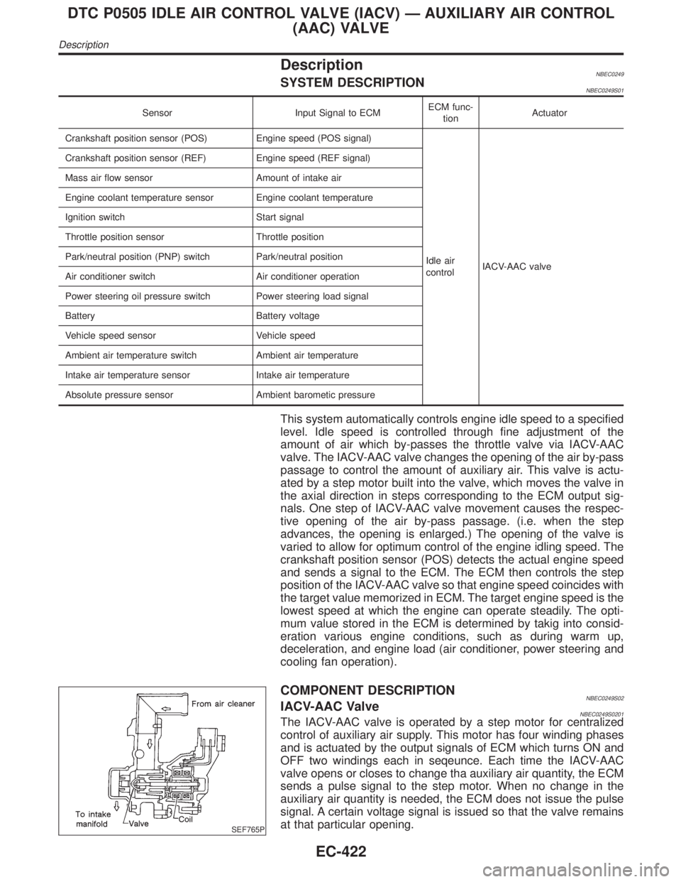
COMPONENT DESCRIPTIONNBEC0249S02IACV-AAC ValveNBEC0249S0201The IACV-AAC valve is operated by a step motor for centralized
control of auxiliary air supply. This motor has four winding phases
and is actuated by the output signals of ECM which turns ON and
OFF two windings each in seqeunce. Each time the IACV-AAC
valve opens or closes to change tha auxiliary air quantity, the ECM
sends a pulse signal to the step motor. When no change in the
auxiliary air quantity is needed, the ECM does not issue the pulse
signal. A certain voltage signal is issued so that the valve remains
at that particular opening.
DTC P0505 IDLE AIR CONTROL VALVE (IACV) Ð AUXILIARY AIR CONTROL
(AAC) VALVE
Description
EC-422
Page 966 of 2395

SEF505V
Component DescriptionNBEC0256A closed throttle position switch and wide open throttle position
switch are built into the throttle position sensor unit. The wide open
throttle position switch is used only for A/T control.
When the throttle valve is in the closed position, the closed throttle
position switch sends a voltage signal to the ECM. The ECM only
uses this signal to open or close the EVAP canister purge volume
control solenoid valve when the throttle position sensor is malfunc-
tioning.
CONSULT-II Reference Value in Data Monitor
Mode
NBEC0257Specification data are reference values.
MONITOR ITEM CONDITION SPECIFICATION
CLSD THL/P SWIEngine: After warming up, idle
the engineThrottle valve: Idle position ON
Throttle valve: Slightly open OFF
ECM Terminals and Reference ValueNBEC0671Specification data are reference values and are measured between each terminal and ground.
CAUTION:
Do not use ECM ground terminals when measuring input/output voltage. Doing so may result in dam-
age to the ECM's transistor. Use a ground other than ECM terminals, such as the ground.
TERMI-
NAL
NO.WIRE
COLORITEM CONDITION DATA (DC Voltage)
56 OR/LThrottle position switch
(Closed position)[Engine is running]
IAccelerator pedal fully releasedBATTERY VOLTAGE
(11 - 14V)
[Engine is running]
IAccelerator pedal depressedApproximately 0V
On Board Diagnosis LogicNBEC0259Malfunction is detected when battery voltage from the closed
throttle position switch is sent to ECM with the throttle valve
opened.
Possible CauseNBEC0516IHarness or connectors
(The closed throttle position switch circuit is shorted.)
IClosed throttle position switch
IThrottle position sensor
GI
MA
EM
LC
FE
AT
TF
PD
AX
SU
BR
ST
RS
BT
HA
SC
EL
IDX
DTC P0510 CLOSED THROTTLE POSITION SWITCH
Component Description
EC-431
Page 973 of 2395

7 ADJUST THROTTLE POSITION SWITCH
Check the following items. Refer to ªBasic Inspectionº, EC-101.
MTBL0655
Is it possible to adjust closed throttle position switch?
YesorNo
Yes (With CONSULT-II)©GO TO 9.
Yes (Without CONSULT-
II)©GO TO 9.
No©Replace throttle position switch.
8 CHECK THROTTLE POSITION SENSOR
With CONSULT-II
1. Start engine and warm it up to normal operating temperature.
2. Stop engine (ignition switch OFF).
3. Remove the vacuum hose connected to the throttle opener.
4. Connect suitable vacuum hose to the vacuum pump and the opener.
5. Apply vacuum [more than þ40.0 kPa (þ300 mmHg, þ11.81 inHg)] until the throttle drum becomes free from the rod of
the throttle opener.
SEF793W
6. Turn ignition switch ON.
7. Select ªDATA MONITORº mode with CONSULT-II.
8. Check voltage of ªTHRTL POS SENº under the following conditins.
Voltage measurement must be made with throttle position sensor installed in vehicle.
MTBL0230
OK or NG
OK©GO TO 10.
NG©Replace throttle position sensor.
DTC P0510 CLOSED THROTTLE POSITION SWITCH
Diagnostic Procedure (Cont'd)
EC-438
Page 974 of 2395

9 CHECK THROTTLE POSITION SENSOR
1. Start engine and warm it up to normal operating temperature.
2. Stop engine (ignition switch OFF).
3. Remove the vacuum hose connected to the throttle opener.
4. Connect suitable vacuum hose to the vacuum pump and the opener.
5. Apply vacuum [more than þ40.0 kPa (þ300 mmHg, þ11.81 inHg)] until the throttle drum becomes free from the rod of
the throttle opener.
SEF793W
6. Turn ignition switch ON.
7. Check voltage between ECM terminal 91 (Throttle position sensor signal) and ground.
Voltage measurement must be made with throttle position sensor installed in vehicle.
SEF348X
OK or NG
OK©GO TO 10.
NG©Replace throttle position sensor.
10 CHECK INTERMITTENT INCIDENT
Refer to ªTROUBLE DIAGNOSIS FOR INTERMITTENT INCIDENTº, EC-140.
©INSPECTION END
GI
MA
EM
LC
FE
AT
TF
PD
AX
SU
BR
ST
RS
BT
HA
SC
EL
IDX
DTC P0510 CLOSED THROTTLE POSITION SWITCH
Diagnostic Procedure (Cont'd)
EC-439
Page 981 of 2395

DescriptionNBEC0691SYSTEM DESCRIPTIONNBEC0691S01
Sensor Input signal to ECM function ECM Actuator
Crankshaft positon sensor (POS) Engine speed (POS)
Intake valve
timing con-
trolIntake valve timing control sole-
noid valve Crankshaft position sensor (REF) Engine speed (REF)
Camshaft position sensor Engine speed
Engine coolant temperature sensor Engine coolant temperature
Vehicle speed sensor Vehicle speed
JEF349Z
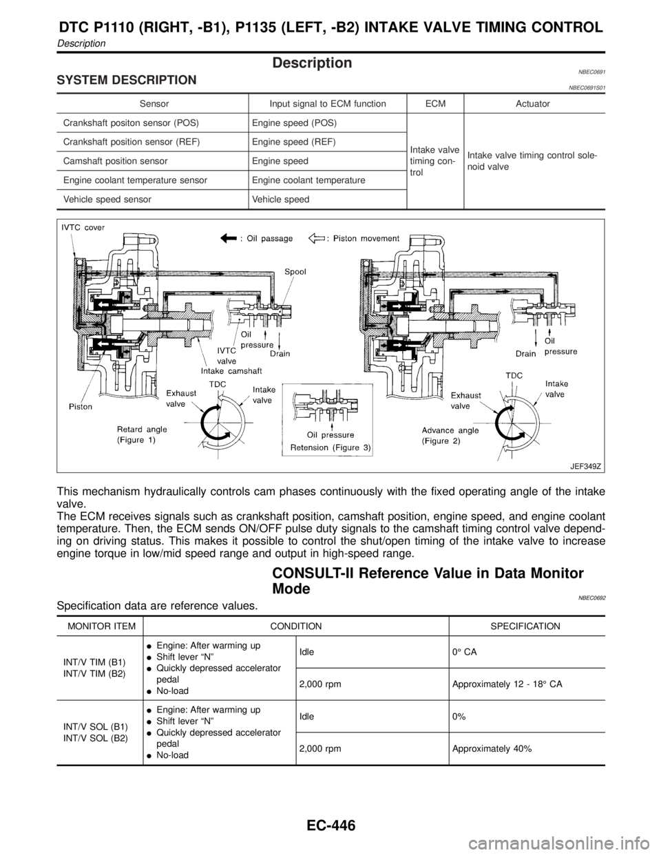
This mechanism hydraulically controls cam phases continuously with the fixed operating angle of the intake
valve.
The ECM receives signals such as crankshaft position, camshaft position, engine speed, and engine coolant
temperature. Then, the ECM sends ON/OFF pulse duty signals to the camshaft timing control valve depend-
ing on driving status. This makes it possible to control the shut/open timing of the intake valve to increase
engine torque in low/mid speed range and output in high-speed range.
CONSULT-II Reference Value in Data Monitor
Mode
NBEC0692Specification data are reference values.
MONITOR ITEM CONDITION SPECIFICATION
INT/V TIM (B1)
INT/V TIM (B2)IEngine: After warming up
IShift lever ªNº
IQuickly depressed accelerator
pedal
INo-loadIdle 0É CA
2,000 rpm Approximately 12 - 18É CA
INT/V SOL (B1)
INT/V SOL (B2)IEngine: After warming up
IShift lever ªNº
IQuickly depressed accelerator
pedal
INo-loadIdle 0%
2,000 rpm Approximately 40%
DTC P1110 (RIGHT, -B1), P1135 (LEFT, -B2) INTAKE VALVE TIMING CONTROL
Description
EC-446
Page 983 of 2395
![INFINITI QX4 2001 Factory Service Manual TERMI-
NAL
NO.WIRE
COLORITEM CONDITION DATA (DC Voltage)
89 ORIntake valve timing
control position sen-
sors (LH)[Engine is running]
IWarm-up condition
IIdle speedApproximately 0.5V
SEF351Z
[Engine is INFINITI QX4 2001 Factory Service Manual TERMI-
NAL
NO.WIRE
COLORITEM CONDITION DATA (DC Voltage)
89 ORIntake valve timing
control position sen-
sors (LH)[Engine is running]
IWarm-up condition
IIdle speedApproximately 0.5V
SEF351Z
[Engine is](/manual-img/42/57027/w960_57027-982.png)
TERMI-
NAL
NO.WIRE
COLORITEM CONDITION DATA (DC Voltage)
89 ORIntake valve timing
control position sen-
sors (LH)[Engine is running]
IWarm-up condition
IIdle speedApproximately 0.5V
SEF351Z
[Engine is running]
IWarm-up condition
IEngine speed is 2,000 rpm.Approximately 0.5V
SEF352Z
On Board Diagnosis LogicNBEC0694Malfunction is detected when:
(Malfunction A)
The alignment of the intake valve timing control has been misreg-
istered.
(Malfunction B)
There is a gap between angle of target and phase-control angle
degree.
FAIL-SAFE MODENBEC0694S01When malfunction A or B is detected, the ECM enters fail-safe
mode and the MIL lights up.
Detected items Engine operating condition in fail-safe mode
Intake valve timing control The signal is not energized to the solenoid valve and the valve control does not function.
Possible CauseNBEC0695MALFUNCTION A OR BNBEC0695S01IHarness or connectors
(Intake valve timing control position sensor circuit is open or
shorted.) Refer to EC-482.
ICrankshaft position sensor (REF)
ICrankshaft position sensor (POS)
ICamshaft position sensor (PHASE)
DTC P1110 (RIGHT, -B1), P1135 (LEFT, -B2) INTAKE VALVE TIMING CONTROL
ECM Terminals and Reference Value (Cont'd)
EC-448
Page 984 of 2395

DTC Confirmation ProcedureNBEC0696CAUTION:
Always drive at a safe speed.
NOTE:
IIf both DTC P1111(B1), P1136 (B2) or P1140 (B1), P1145
(B2) and P1110 (B1), P1135 (B2) are displayed, perform
trouble diagnosis for ªDTC P1111(B1), P1136 (B2) or
P1140 (B1), P1145 (B2)º first. (See EC-451, 482.)
IIf ªDTC Confirmation Procedureº has been previously
conducted, always turn ignition switch ªOFFº and wait at
least 10 seconds before conducting the next test.
SEF353Z
PROCEDURE FOR MALFUNCTION ANBEC0696S01With CONSULT-IINBEC0696S01011) Turn ignition switch ªONº.
2) Select ªDATA MONITORº mode with CONSULT-II.
3) Maintain the following conditions for at least 10 consecutive
seconds.
ENG SPEED More than 2,000 rpm
COOLANT TEMPS More than 70ÉC (158ÉF)
Selector lever 1st position
Driving locationDriving vehicle uphill
(Increased engine load will help main-
tain the driving conditions required for
this test.)
4) Maintain the following conditions for at least 20 consecutive
seconds.
ENG SPEED Idle
COOLANT TEMPS More than 70ÉC (158ÉF)
Selector lever ªPº or ªNº position
5) If 1st trip DTC is detected, go to ªP1140, P1145 INTAKE
VALVE TIMING CONTROL POSITION SENSORº. Refer to
EC-482.
With GSTNBEC0696S0102Follow the procedure ªWith CONSULT-IIº above.
GI
MA
EM
LC
FE
AT
TF
PD
AX
SU
BR
ST
RS
BT
HA
SC
EL
IDX
DTC P1110 (RIGHT, -B1), P1135 (LEFT, -B2) INTAKE VALVE TIMING CONTROL
DTC Confirmation Procedure
EC-449