2001 INFINITI QX4 wiring
[x] Cancel search: wiringPage 2136 of 2395
![INFINITI QX4 2001 Factory Service Manual Diagnostic item Explanation Repair order
SIDE MODULE LH
[OPEN]ISide air bag module (LH) circuit is open. 1. Visually check the wiring harness
connection.
2. Replace the harness if it has visible
damag INFINITI QX4 2001 Factory Service Manual Diagnostic item Explanation Repair order
SIDE MODULE LH
[OPEN]ISide air bag module (LH) circuit is open. 1. Visually check the wiring harness
connection.
2. Replace the harness if it has visible
damag](/manual-img/42/57027/w960_57027-2135.png)
Diagnostic item Explanation Repair order
SIDE MODULE LH
[OPEN]ISide air bag module (LH) circuit is open. 1. Visually check the wiring harness
connection.
2. Replace the harness if it has visible
damage.
3. If the harness check is OK, replace
the diagnosis sensor unit and side
air bag module (LH). (Before dis-
posing the side air bag module
(LH), it must be deployed.) SIDE MODULE LH
[VB-SHORT]ISide air bag module (LH) circuit is shorted to some power
supply circuits.
SIDE MODULE LH
[GND-SHORT]ISide air bag module (LH) circuit is shorted to ground.
SIDE MODULE LH
[SHORT]ISide air bag module (LH) circuits are shorted to each other.
SIDE MODULE RH
[OPEN]ISide air bag module (RH) circuit is open. 1. Visually check the wiring harness
connection.
2. Replace the harness if it has visible
damage.
3. If the harness check is OK, replace
the diagnosis sensor unit and side
air bag module (RH). (Before dis-
posing the side air bag module
(RH), it must be deployed.) SIDE MODULE RH
[VB-SHORT]ISide air bag module (RH) circuit is shorted to some power
supply circuits.
SIDE MODULE RH
[GND-SHORT]ISide air bag module (RH) circuit is shorted to ground.
SIDE MODULE RH
[SHORT]ISide air bag module (RH) circuits are shorted to each other.
SATELLITE SENS LH
[UNIT FAIL]
SATELLITE SENS LH
[COMM FAIL]ISatellite sensor (LH) 1. Visually check the wiring harness
connection.
2. Replace the harness if it has visible
damage.
3. If the harness check is OK, replace
the diagnosis sensor unit and satel-
lite sensor (LH).
SATELLITE SENS RH
[UNIT FAIL]
SATELLITE SENS RH
[COMM FAIL]ISatellite sensor (RH) 1. Visually check the wiring harness
connection.
2. Replace the harness if it has visible
damage.
3. If the harness check is OK, replace
the diagnosis sensor unit and satel-
lite sensor (RH).
PRE-TEN FRONT LH
[OPEN/VB-SHORT]IThe circuit for front LH pre-tensioner is open or shorted to
some power supply circuit.1. Visually check the wiring harness
connections.
2. Replace the harness if it has visible
damage.
3. If the harness check is OK, replace
the diagnosis sensor unit and front
LH seat belt.
(Before disposing the front LH seat
belt pre-tensioner, it must be
deployed.) PRE-TEN FRONT LH
[GND-SHORT]IThe circuit for front LH pre-tensioner is shorted to ground.
PRE-TEN FRONT RH
[OPEN/VB-SHORT]IThe circuit for front RH pre-tensioner is open or shorted to
some power supply circuit.1. Visually check the wiring harness
connections.
2. Replace the harness if it has visible
damage.
3. If the harness check is OK, replace
the diagnosis sensor unit and front
RH seat belt.
(Before disposing the front RH seat
belt pre-tensioner, it must be
deployed.) PRE-TEN FRONT RH
[GND-SHORT]IThe circuit for front RH pre-tensioner is shorted to ground.
GI
MA
EM
LC
EC
FE
AT
TF
PD
AX
SU
BR
ST
BT
HA
SC
EL
IDX
SUPPLEMENTAL RESTRAINT SYSTEM (SRS)
Trouble Diagnoses with CONSULT-II (Cont'd)
RS-47
Page 2137 of 2395
Diagnostic item Explanation Repair order
CONTROL UNITIDiagnosis sensor unit is malfunctioning. 1. Visually check the wiring harness
connection.
2. Replace the harness if it has visible
damage.
3. If the harness check is OK, replace
the diagnosis sensor unit.
* Follow the procedures in numerical order when repairing malfunctioning parts, then make the final system check.
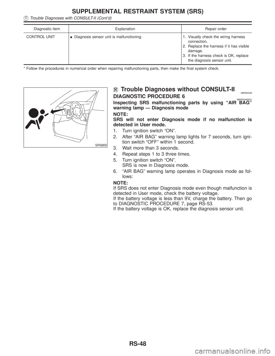
SRS800
Trouble Diagnoses without CONSULT-IINBRS0046DIAGNOSTIC PROCEDURE 6NBRS0046S01Inspecting SRS malfunctioning parts by using ªAIR BAGº
warning lamp Ð Diagnosis mode
NOTE:
SRS will not enter Diagnosis mode if no malfunction is
detected in User mode.
1. Turn ignition switch ªONº.
2. After ªAIR BAGº warning lamp lights for 7 seconds, turn igni-
tion switch ªOFFº within 1 second.
3. Wait more than 3 seconds.
4. Repeat steps 1 to 3 three times.
5. Turn ignition switch ªONº.
SRS is now in Diagnosis mode.
6. ªAIR BAGº warning lamp operates in Diagnosis mode as fol-
lows:
NOTE:
If SRS does not enter Diagnosis mode even though malfunction is
detected in User mode, check the battery voltage.
If the battery voltage is less than 9V, charge the battery. Then go
to DIAGNOSTIC PROCEDURE 7, page RS-53.
If the battery voltage is OK, replace the diagnosis sensor unit.
SUPPLEMENTAL RESTRAINT SYSTEM (SRS)
Trouble Diagnoses with CONSULT-II (Cont'd)
RS-48
Page 2139 of 2395
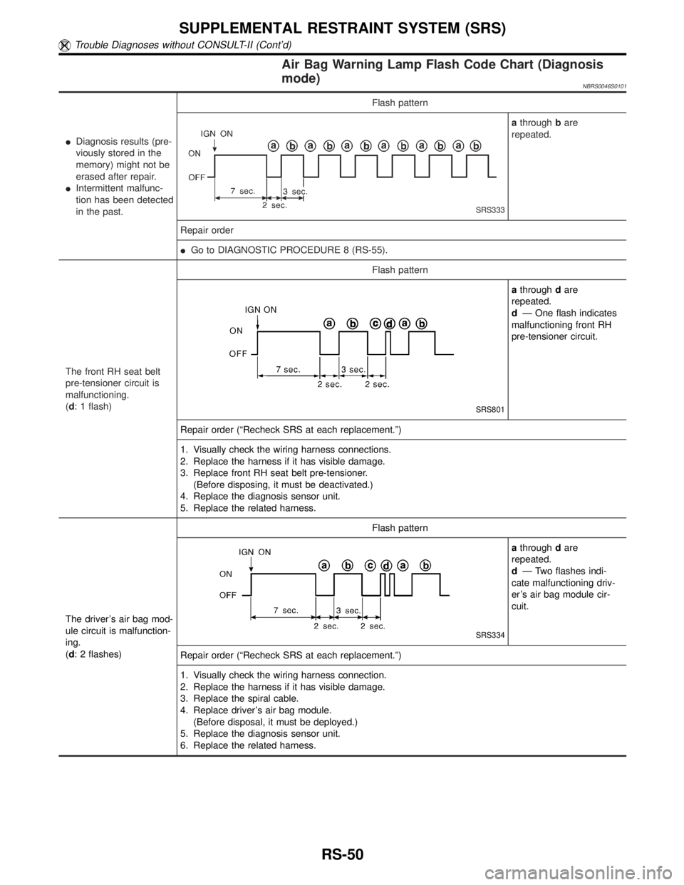
Air Bag Warning Lamp Flash Code Chart (Diagnosis
mode)
NBRS0046S0101
IDiagnosis results (pre-
viously stored in the
memory) might not be
erased after repair.
IIntermittent malfunc-
tion has been detected
in the past.Flash pattern
SRS333
athroughbare
repeated.
Repair order
IGo to DIAGNOSTIC PROCEDURE 8 (RS-55).
The front RH seat belt
pre-tensioner circuit is
malfunctioning.
(d: 1 flash)Flash pattern
SRS801
athroughdare
repeated.
dÐ One flash indicates
malfunctioning front RH
pre-tensioner circuit.
Repair order (ªRecheck SRS at each replacement.º)
1. Visually check the wiring harness connections.
2. Replace the harness if it has visible damage.
3. Replace front RH seat belt pre-tensioner.
(Before disposing, it must be deactivated.)
4. Replace the diagnosis sensor unit.
5. Replace the related harness.
The driver's air bag mod-
ule circuit is malfunction-
ing.
(d: 2 flashes)Flash pattern
SRS334
athroughdare
repeated.
dÐ Two flashes indi-
cate malfunctioning driv-
er's air bag module cir-
cuit.
Repair order (ªRecheck SRS at each replacement.º)
1. Visually check the wiring harness connection.
2. Replace the harness if it has visible damage.
3. Replace the spiral cable.
4. Replace driver's air bag module.
(Before disposal, it must be deployed.)
5. Replace the diagnosis sensor unit.
6. Replace the related harness.
SUPPLEMENTAL RESTRAINT SYSTEM (SRS)
Trouble Diagnoses without CONSULT-II (Cont'd)
RS-50
Page 2140 of 2395

The front LH seat belt
pre-tensioner circuit is
malfunctioning.
(d: 3 flashes)Flash pattern
SRS802
athroughdare
repeated.
dÐ Three flashes indi-
cate malfunctioning front
LH pre-tensioner circuit.
Repair order (ªRecheck SRS at each replacement.º)
1. Visually check the wiring harness connections.
2. Replace the harness if it has visible damage.
3. Replace front LH seat belt pre-tensioner.
(Before disposing, it must be deactivated.)
4. Replace the diagnosis sensor unit.
5. Replace the related harness.
The diagnosis sensor
unit is malfunctioning.
(d: 7 flashes)Flash pattern
SRS335
athroughdare
repeated.
dÐ Seven flashes indi-
cate malfunctioning diag-
nosis sensor unit.
Repair order (ªRecheck SRS at each replacement.º)
1. Visually check the wiring harness connections.
2. Replace the harness if it has visible damage.
3. Replace the diagnosis sensor unit.
4. Replace the related harness.
The front passenger air
bag module circuit is
malfunctioning.
(d: 8 flashes)Flash pattern
SRS336
athroughdare
repeated.
dÐ Eight flashes indi-
cate malfunctioning front
passenger air bag mod-
ule circuit.
Repair order (ªRecheck SRS at each replacement.º)
1. Visually check the wiring harness connection.
2. Replace the harness if it has visible damage.
3. Replace front passenger air bag module.
(Before disposal, it must be deployed.)
4. Replace the diagnosis sensor unit.
5. Replace the related harness.
GI
MA
EM
LC
EC
FE
AT
TF
PD
AX
SU
BR
ST
BT
HA
SC
EL
IDX
SUPPLEMENTAL RESTRAINT SYSTEM (SRS)
Trouble Diagnoses without CONSULT-II (Cont'd)
RS-51
Page 2141 of 2395
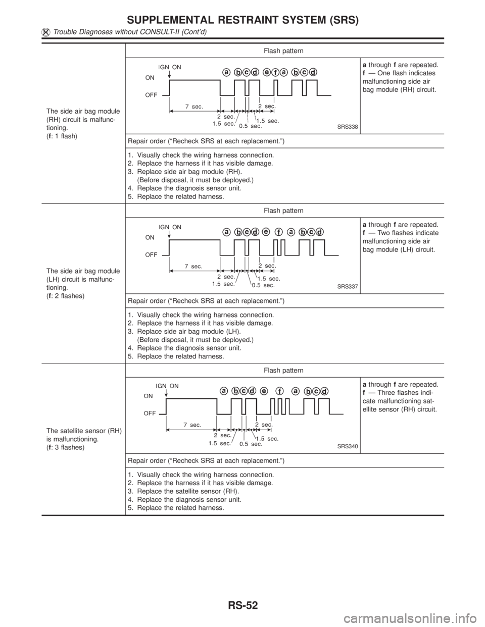
The side air bag module
(RH) circuit is malfunc-
tioning.
(f: 1 flash)Flash pattern
SRS338
athroughfare repeated.
fÐ One flash indicates
malfunctioning side air
bag module (RH) circuit.
Repair order (ªRecheck SRS at each replacement.º)
1. Visually check the wiring harness connection.
2. Replace the harness if it has visible damage.
3. Replace side air bag module (RH).
(Before disposal, it must be deployed.)
4. Replace the diagnosis sensor unit.
5. Replace the related harness.
The side air bag module
(LH) circuit is malfunc-
tioning.
(f: 2 flashes)Flash pattern
SRS337
athroughfare repeated.
fÐ Two flashes indicate
malfunctioning side air
bag module (LH) circuit.
Repair order (ªRecheck SRS at each replacement.º)
1. Visually check the wiring harness connection.
2. Replace the harness if it has visible damage.
3. Replace side air bag module (LH).
(Before disposal, it must be deployed.)
4. Replace the diagnosis sensor unit.
5. Replace the related harness.
The satellite sensor (RH)
is malfunctioning.
(f: 3 flashes)Flash pattern
SRS340
athroughfare repeated.
fÐ Three flashes indi-
cate malfunctioning sat-
ellite sensor (RH) circuit.
Repair order (ªRecheck SRS at each replacement.º)
1. Visually check the wiring harness connection.
2. Replace the harness if it has visible damage.
3. Replace the satellite sensor (RH).
4. Replace the diagnosis sensor unit.
5. Replace the related harness.
SUPPLEMENTAL RESTRAINT SYSTEM (SRS)
Trouble Diagnoses without CONSULT-II (Cont'd)
RS-52
Page 2142 of 2395
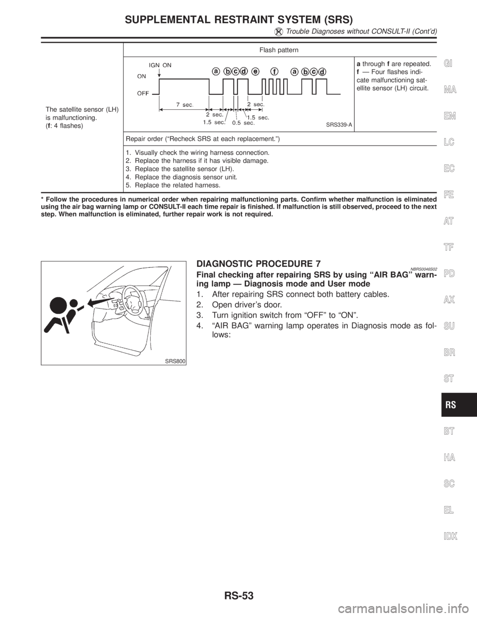
The satellite sensor (LH)
is malfunctioning.
(f: 4 flashes)Flash pattern
SRS339-A
athroughfare repeated.
fÐ Four flashes indi-
cate malfunctioning sat-
ellite sensor (LH) circuit.
Repair order (ªRecheck SRS at each replacement.º)
1. Visually check the wiring harness connection.
2. Replace the harness if it has visible damage.
3. Replace the satellite sensor (LH).
4. Replace the diagnosis sensor unit.
5. Replace the related harness.
* Follow the procedures in numerical order when repairing malfunctioning parts. Confirm whether malfunction is eliminated
using the air bag warning lamp or CONSULT-II each time repair is finished. If malfunction is still observed, proceed to the next
step. When malfunction is eliminated, further repair work is not required.
SRS800
DIAGNOSTIC PROCEDURE 7NBRS0046S02Final checking after repairing SRS by using ªAIR BAGº warn-
ing lamp Ð Diagnosis mode and User mode
1. After repairing SRS connect both battery cables.
2. Open driver's door.
3. Turn ignition switch from ªOFFº to ªONº.
4. ªAIR BAGº warning lamp operates in Diagnosis mode as fol-
lows:
GI
MA
EM
LC
EC
FE
AT
TF
PD
AX
SU
BR
ST
BT
HA
SC
EL
IDX
SUPPLEMENTAL RESTRAINT SYSTEM (SRS)
Trouble Diagnoses without CONSULT-II (Cont'd)
RS-53
Page 2146 of 2395
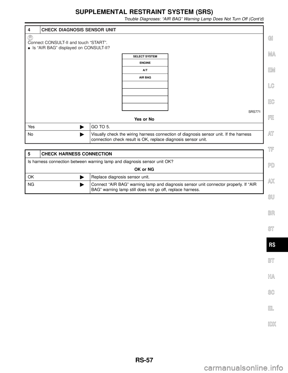
4 CHECK DIAGNOSIS SENSOR UNIT
Connect CONSULT-II and touch ªSTARTº.
IIs ªAIR BAGº displayed on CONSULT-II?
SRS771
YesorNo
Ye s©GO TO 5.
No©Visually check the wiring harness connection of diagnosis sensor unit. If the harness
connection check result is OK, replace diagnosis sensor unit.
5 CHECK HARNESS CONNECTION
Is harness connection between warning lamp and diagnosis sensor unit OK?
OK or NG
OK©Replace diagnosis sensor unit.
NG©Connect ªAIR BAGº warning lamp and diagnosis sensor unit connector properly. If ªAIR
BAGº warning lamp still does not go off, replace harness.
GI
MA
EM
LC
EC
FE
AT
TF
PD
AX
SU
BR
ST
BT
HA
SC
EL
IDX
SUPPLEMENTAL RESTRAINT SYSTEM (SRS)
Trouble Diagnoses: ªAIR BAGº Warning Lamp Does Not Turn Off (Cont'd)
RS-57
Page 2152 of 2395
STARTING & CHARGING SYSTEM
SECTION
SC
CONTENTS
PRECAUTIONS...............................................................2
Supplemental Restraint System (SRS)²AIR
BAG²and²SEAT BELT PRE-TENSIONER²...............2
Wiring Diagrams and Trouble Diagnosis .....................2
PREPARATION...............................................................3
Special Service Tool ....................................................3
BATTERY.........................................................................4
How to Handle Battery ................................................4
METHODS OF PREVENTING OVER-DISCHARGE......4
CHECKING ELECTROLYTE LEVEL............................4
SPECIFIC GRAVITY CHECK......................................5
CHARGING THE BATTERY........................................6
Trouble Diagnoses with Battery/Starting/Charging
System Tester ..............................................................7
DIAGNOSTIC RESULT ITEM CHART..........................9
STARTING SYSTEM.....................................................10
System Description ....................................................10
Wiring Diagram - START -......................................... 11
Trouble Diagnoses with Battery/Starting/Charging
System Tester ............................................................12
DIAGNOSTIC RESULT ITEM CHART........................13
WORK FLOW..........................................................14
DIAGNOSTIC PROCEDURE 1..................................15
DIAGNOSTIC PROCEDURE 2..................................17
MINIMUM SPECIFICATION OF CRANKING
VOLTAGE REFERENCING COOLANT
TEMPERATURE
......................................................17
Construction ...............................................................18
Removal and Installation ...........................................18
Pinion/Clutch Check ..................................................18
CHARGING SYSTEM....................................................19
System Description ....................................................19
Wiring Diagram - CHARGE -.....................................20
Trouble Diagnoses with Battery/Starting/Charging
System Tester ............................................................21
DIAGNOSTIC RESULT ITEM CHART........................23
WORK FLOW..........................................................24
DIAGNOSTIC PROCEDURE 1..................................25
DIAGNOSTIC PROCEDURE 2..................................26
DIAGNOSTIC PROCEDURE 3..................................27
MALFUNCTION INDICATOR....................................27
Construction ...............................................................28
Removal and Installation ...........................................28
SERVICE DATA AND SPECIFICATIONS (SDS).........29
Battery........................................................................29
Starter ........................................................................29
Alternator ...................................................................29
GI
MA
EM
LC
EC
FE
AT
TF
PD
AX
SU
BR
ST
RS
BT
HA
EL
IDX