Page 2264 of 2395

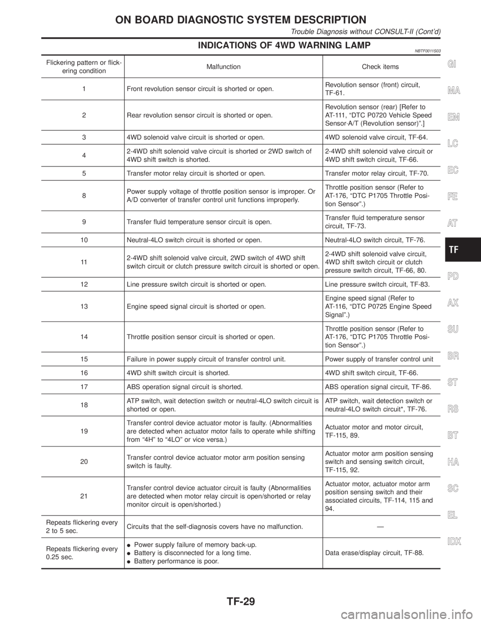
INDICATIONS OF 4WD WARNING LAMPNBTF0011S03
Flickering pattern or flick-
ering conditionMalfunction Check items
1 Front revolution sensor circuit is shorted or open.Revolution sensor (front) circuit,
TF-61.
2 Rear revolution sensor circuit is shorted or open.Revolution sensor (rear) [Refer to
AT-111, ªDTC P0720 Vehicle Speed
Sensor´A/T (Revolution sensor)º.]
3 4WD solenoid valve circuit is shorted or open. 4WD solenoid valve circuit, TF-64.
42-4WD shift solenoid valve circuit is shorted or 2WD switch of
4WD shift switch is shorted.2-4WD shift solenoid valve circuit or
4WD shift switch circuit, TF-66.
5 Transfer motor relay circuit is shorted or open. Transfer motor relay circuit, TF-70.
8Power supply voltage of throttle position sensor is improper. Or
A/D converter of transfer control unit functions improperly.Throttle position sensor (Refer to
AT-176, ªDTC P1705 Throttle Posi-
tion Sensorº.)
9 Transfer fluid temperature sensor circuit is open.Transfer fluid temperature sensor
circuit, TF-73.
10 Neutral-4LO switch circuit is shorted or open. Neutral-4LO switch circuit, TF-76.
112-4WD shift solenoid valve circuit, 2WD switch of 4WD shift
switch circuit or clutch pressure switch circuit is shorted or open.2-4WD shift solenoid valve circuit,
4WD shift switch circuit or clutch
pressure switch circuit, TF-66, 80.
12 Line pressure switch circuit is shorted or open. Line pressure switch circuit, TF-83.
13 Engine speed signal circuit is shorted or open.Engine speed signal (Refer to
AT-116, ªDTC P0725 Engine Speed
Signalº.)
14 Throttle position sensor circuit is shorted or open.Throttle position sensor (Refer to
AT-176, ªDTC P1705 Throttle Posi-
tion Sensorº.)
15 Failure in power supply circuit of transfer control unit. Power supply of transfer control unit
16 4WD shift switch circuit is shorted. 4WD shift switch circuit, TF-66.
17 ABS operation signal circuit is shorted. ABS operation signal circuit, TF-86.
18ATP switch, wait detection switch or neutral-4LO switch circuit is
shorted or open.ATP switch, wait detection switch or
neutral-4LO switch circuit*, TF-76.
19Transfer control device actuator motor is faulty. (Abnormalities
are detected when actuator motor fails to operate while shifting
from ª4Hº to ª4LOº or vice versa.)Actuator motor and motor circuit,
TF-115, 89.
20Transfer control device actuator motor arm position sensing
switch is faulty.Actuator motor arm position sensing
switch and sensing switch circuit,
TF-115, 92.
21Transfer control device actuator circuit is faulty (Abnormalities
are detected when motor relay circuit is open/shorted or relay
monitor circuit is open/shorted.)Actuator motor, actuator motor arm
position sensing switch and their
associated circuits, TF-114, 115 and
94.
Repeats flickering every
2 to 5 sec.Circuits that the self-diagnosis covers have no malfunction. Ð
Repeats flickering every
0.25 sec.IPower supply failure of memory back-up.
IBattery is disconnected for a long time.
IBattery performance is poor.Data erase/display circuit, TF-88.GI
MA
EM
LC
EC
FE
AT
PD
AX
SU
BR
ST
RS
BT
HA
SC
EL
IDX
ON BOARD DIAGNOSTIC SYSTEM DESCRIPTION
Trouble Diagnosis without CONSULT-II (Cont'd)
TF-29
Page 2265 of 2395
Flickering pattern or flick-
ering conditionMalfunction Check items
No flickering PNP switch or 4WD shift switch circuit is shorted or open.PNP switch (Refer to AT-99, ªDTC
P0705 Park/Neutral Position
Switchº.) or 4WD shift switch circuit,
TF-66.
*: If revolution sensor malfunction is simultaneously detected, check revolution sensor first.
SAT601J
Trouble Diagnosis with CONSULT-IINBTF0012SELF-DIAGNOSISNBTF0012S01CONSULT-II Setting ProcedureNBTF0012S01011. Turn ignition switch to ªOFFº position.
SMT962D
2. Connect CONSULT-II to data link connector which is located
in instrument lower panel on driver side.
SAT586J
3. Start engine.
4. On CONSULT-II screen, touch ªSTARTº.
SMT964D
5. Touch ªALL MODE 4WDº on SELECT SYSTEM screen.
ON BOARD DIAGNOSTIC SYSTEM DESCRIPTION
Trouble Diagnosis without CONSULT-II (Cont'd)
TF-30
Page 2266 of 2395

SMT965D
6. Touch ªSELF-DIAG RESULTSº on SELECT DIAG MODE
screen.
SMT966D
7. Self-diagnostic results are displayed.
SELF-DIAGNOSTIC ITEMSNBTF0012S02
Detected items
(Screen terms for CONSULT-II,
ªSELF-DIAG RESULTº mode)Malfunction is detected when... Check items
Revolution sensor (front) (Note 3)
(VHCL SPEED SEN´FR)IFront revolution sensor (installed on T/F) signal is not
input due to open circuit.
IImproper signal is input while driving.Revolution sensor (front) circuit,
TF-61.
Revolution sensor (rear)
(VHCL SPEED SEN´RR)ISignal from vehicle speed sensor 1 (installed on A/T)
is not input due to open circuit.
IImproper signal is input while driving.Revolution sensor (rear) [Refer to
AT-111, ªDTC P0720 Vehicle Speed
Sensor´A/T (Revolution sensor)º.]
4WD solenoid valve
(DUTY SOLENOID)
IProper voltage is not applied to solenoid valve due to
open or short circuit.4WD solenoid valve, TF-64.
2-4WD shift solenoid valve
(2-4WD SOLENOID)2-4WD shift solenoid valve or
4WD shift switch circuit, TF-66.
Transfer motor relay
(MOTOR RELAY)IMotor does not operate properly due to open or short
circuit in transfer motor or motor relay.Transfer motor relay circuit,
TF-70.
Transfer fluid temperature sensor
(FLUID TEMP SENSOR)ISignal voltage from fluid temperature sensor is abnor-
mally high (T/F fluid temperature is abnormally low)
while driving.Transfer fluid temperature sensor
circuit, TF-73.
Neutral-4LO switch
(N POSI SW TF)IImproper signal is input while driving. Neutral-4LO switch, TF-76.
Clutch pressure
(CLUTCH PRESSURE)IImproper signal is input due to open or short circuit.
IMalfunction occurs in clutch pressure hydraulic circuit.Clutch pressure switch circuit
(*1), TF-80.
Line pressure
(LINE PRESSURE)IImproper signal is input due to open or short circuit.
IMalfunction occurs in line pressure hydraulic circuit.Line pressure switch circuit (*1),
TF-83.
Engine speed signal (Note 1)
(ENGINE SPEED SIG)IEngine speed is abnormally low while driving.Engine speed signal (Refer to
AT-116, ªDTC P0725 Engine Speed
Signalº.)
GI
MA
EM
LC
EC
FE
AT
PD
AX
SU
BR
ST
RS
BT
HA
SC
EL
IDX
ON BOARD DIAGNOSTIC SYSTEM DESCRIPTION
Trouble Diagnosis with CONSULT-II (Cont'd)
TF-31
Page 2277 of 2395
Diagnostic WorksheetNBTF0013S0202
1.lListen to customer complaints.TF-44
2.lCheck transfer fluid.TF-44
lLeakage
lFluid condition
lFluid level
3.lRoad testingTF-44
l1. Check before engine is started.
l2. Check at idle.
l3. Cruise test
4.lPerform self-diagnosis NG items (with CONSULT-II and without CONSULT-II). TF-30, TF-27
5.lCheck component. Repair or replace the damaged parts. TF-111
6.lPerform final check. Perform road test (1 through 3). TF-44
TROUBLE DIAGNOSIS Ð INTRODUCTION
Introduction (Cont'd)
TF-42
Page 2279 of 2395

Listen to Customer ComplaintsNBTF0015IEach customer feels differently about a problem. It is important
to fully understand the symptoms or conditions for a customer
complaint.
IListen to the customer about how and when the malfunction
occurs, and make good use of it when performing the road test.
Transfer Fluid CheckNBTF0016ICheck fluid for leaks and fluid level. Refer to MA-22, ªCheck-
ing All-mode 4WD Transfer Fluidº.
SMT089D
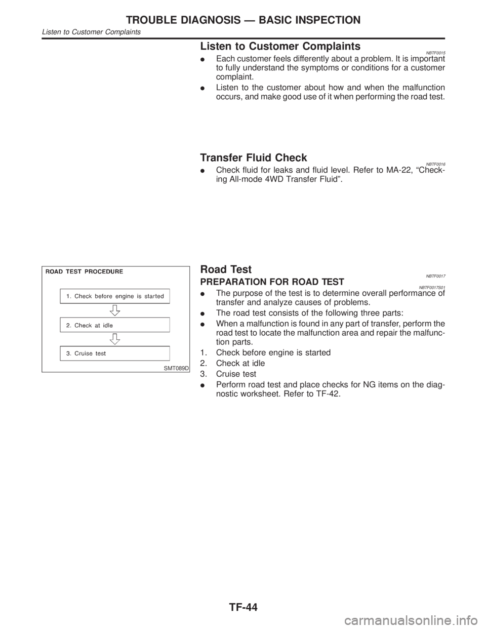
Road TestNBTF0017PREPARATION FOR ROAD TESTNBTF0017S01IThe purpose of the test is to determine overall performance of
transfer and analyze causes of problems.
IThe road test consists of the following three parts:
IWhen a malfunction is found in any part of transfer, perform the
road test to locate the malfunction area and repair the malfunc-
tion parts.
1. Check before engine is started
2. Check at idle
3. Cruise test
IPerform road test and place checks for NG items on the diag-
nostic worksheet. Refer to TF-42.
TROUBLE DIAGNOSIS Ð BASIC INSPECTION
Listen to Customer Complaints
TF-44
Page 2280 of 2395
1. CHECK BEFORE ENGINE IS STARTED=NBTF0017S02
1 CHECK 4WD SHIFT INDICATOR LAMP
1. Park vehicle on flat surface.
2. Turn ignition switch to ªOFFº position.
3. Move A/T selector lever to ªPº position.
4. Set 4WD shift switch to ª4Hº position.
SMT849D
5. Set 4WD shift switch to ª2WDº position.
6. Turn ignition switch to ªONº position. (Do not start engine.)
7. Does 4WD shift indicator lamp turn ON for approx. 1 second?
SMT958D
YesorNo
Ye s©GO TO 2.
No©Go to Symptom 1. Refer to TF-98.
GI
MA
EM
LC
EC
FE
AT
PD
AX
SU
BR
ST
RS
BT
HA
SC
EL
IDX
TROUBLE DIAGNOSIS Ð BASIC INSPECTION
Road Test (Cont'd)
TF-45
Page 2282 of 2395
2. CHECK AT IDLE=NBTF0017S03
1 CHECK 4WD SHIFT INDICATOR LAMP
1. Park vehicle on flat surface.
2. Turn ignition switch to ªOFFº position.
3. Move A/T selector lever to ªPº or ªNº position.
4. Set 4WD shift switch to ª4Hº position.
5. Set 4WD shift switch to ª2WDº position.
6. Start engine.
7. Is 4WD shift indicator lamp turned OFF?
SMT958D
YesorNo
Ye s©Go to ªATP SWITCH, WAIT DETECTION SWITCH AND NEUTRAL-4LO SWITCHº. Refer
to TF-76.
No©GO TO 2.
2 CHECK 4WD WARNING LAMP
Is 4WD warning lamp turned OFF?
YesorNo
Ye s©GO TO 3.
No©Perform self-diagnosis. Refer to ªTrouble Diagnosis without CONSULT-IIº, TF-27.
GI
MA
EM
LC
EC
FE
AT
PD
AX
SU
BR
ST
RS
BT
HA
SC
EL
IDX
TROUBLE DIAGNOSIS Ð BASIC INSPECTION
Road Test (Cont'd)
TF-47
Page 2287 of 2395

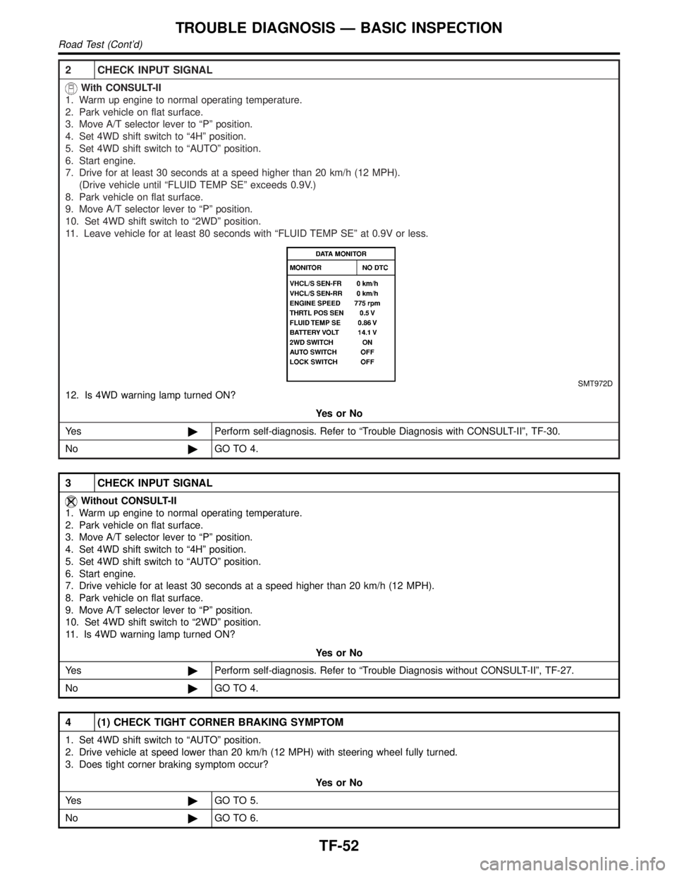
2 CHECK INPUT SIGNAL
With CONSULT-II
1. Warm up engine to normal operating temperature.
2. Park vehicle on flat surface.
3. Move A/T selector lever to ªPº position.
4. Set 4WD shift switch to ª4Hº position.
5. Set 4WD shift switch to ªAUTOº position.
6. Start engine.
7. Drive for at least 30 seconds at a speed higher than 20 km/h (12 MPH).
(Drive vehicle until ªFLUID TEMP SEº exceeds 0.9V.)
8. Park vehicle on flat surface.
9. Move A/T selector lever to ªPº position.
10. Set 4WD shift switch to ª2WDº position.
11. Leave vehicle for at least 80 seconds with ªFLUID TEMP SEº at 0.9V or less.
SMT972D
12. Is 4WD warning lamp turned ON?
YesorNo
Ye s©Perform self-diagnosis. Refer to ªTrouble Diagnosis with CONSULT-IIº, TF-30.
No©GO TO 4.
3 CHECK INPUT SIGNAL
Without CONSULT-II
1. Warm up engine to normal operating temperature.
2. Park vehicle on flat surface.
3. Move A/T selector lever to ªPº position.
4. Set 4WD shift switch to ª4Hº position.
5. Set 4WD shift switch to ªAUTOº position.
6. Start engine.
7. Drive vehicle for at least 30 seconds at a speed higher than 20 km/h (12 MPH).
8. Park vehicle on flat surface.
9. Move A/T selector lever to ªPº position.
10. Set 4WD shift switch to ª2WDº position.
11. Is 4WD warning lamp turned ON?
YesorNo
Ye s©Perform self-diagnosis. Refer to ªTrouble Diagnosis without CONSULT-IIº, TF-27.
No©GO TO 4.
4 (1) CHECK TIGHT CORNER BRAKING SYMPTOM
1. Set 4WD shift switch to ªAUTOº position.
2. Drive vehicle at speed lower than 20 km/h (12 MPH) with steering wheel fully turned.
3. Does tight corner braking symptom occur?
YesorNo
Ye s©GO TO 5.
No©GO TO 6.
TROUBLE DIAGNOSIS Ð BASIC INSPECTION
Road Test (Cont'd)
TF-52