Page 2017 of 2395
2WD, 4WD model
8.5(9 US qt, 7-1/2 Imp qt)
Drain plug:
: 29 - 39 N´m (3.0 - 4.0 kg-m, 22 - 29 ft-lb)
4. Run engine at idle speed for five minutes.
5. Check fluid level and condition. Refer to MA-21, ªChecking A/T
Fluidº. If fluid is still dirty, repeat steps 2 through 5.
SMA439B
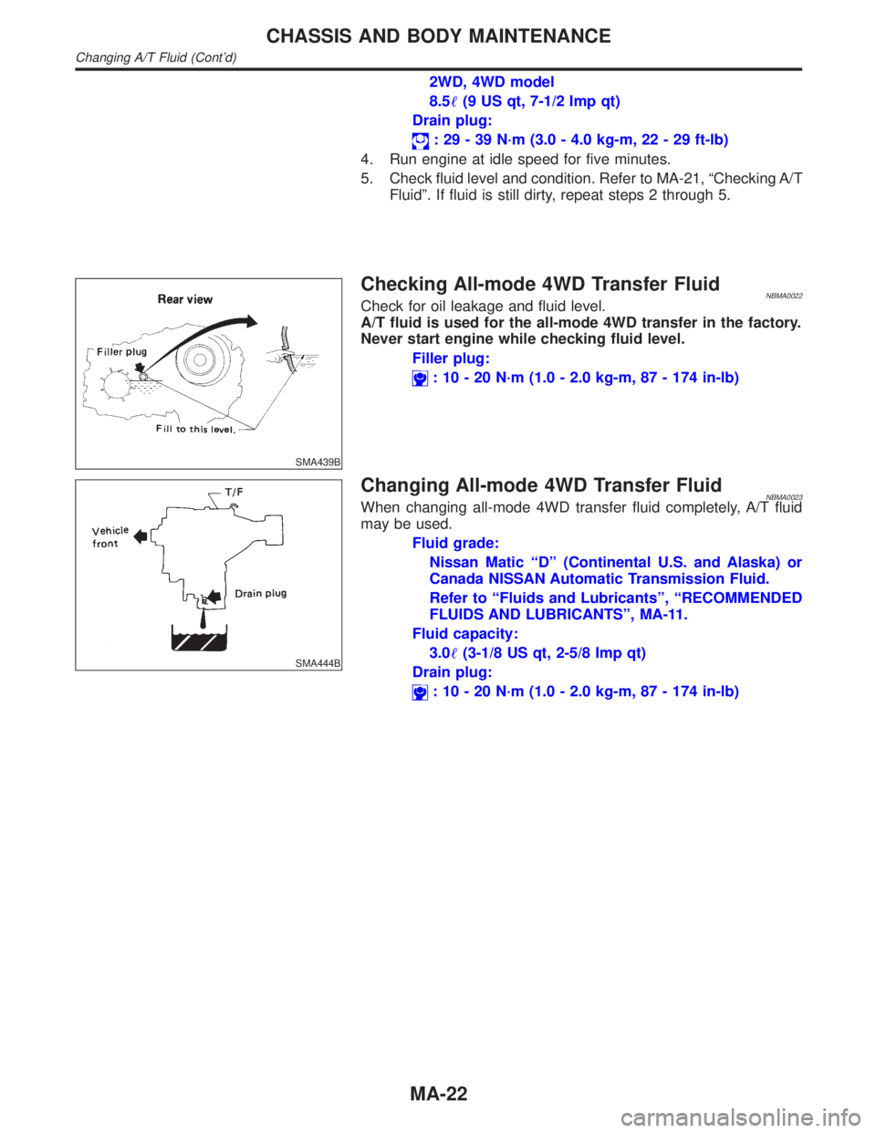
Checking All-mode 4WD Transfer FluidNBMA0022Check for oil leakage and fluid level.
A/T fluid is used for the all-mode 4WD transfer in the factory.
Never start engine while checking fluid level.
Filler plug:
: 10 - 20 N´m (1.0 - 2.0 kg-m, 87 - 174 in-lb)
SMA444B
Changing All-mode 4WD Transfer FluidNBMA0023When changing all-mode 4WD transfer fluid completely, A/T fluid
may be used.
Fluid grade:
Nissan Matic ªDº (Continental U.S. and Alaska) or
Canada NISSAN Automatic Transmission Fluid.
Refer to ªFluids and Lubricantsº, ªRECOMMENDED
FLUIDS AND LUBRICANTSº, MA-11.
Fluid capacity:
3.0(3-1/8 US qt, 2-5/8 Imp qt)
Drain plug:
: 10 - 20 N´m (1.0 - 2.0 kg-m, 87 - 174 in-lb)
CHASSIS AND BODY MAINTENANCE
Changing A/T Fluid (Cont'd)
MA-22
Page 2022 of 2395
SST280B
Checking Power Steering Fluid and LinesNBMA0035CHECKING FLUID LEVELNBMA0035S01ICheck fluid level with engine off.
ICheck fluid level with dipstick on reservoir cap. Use ªHOTº
range at fluid temperatures of 50 to 80ÉC (122 to 176ÉF). Use
ªCOLDº range at fluid temperatures of 0 to 30ÉC (32 to 86ÉF).
CAUTION:
IDo not overfill.
IRecommended fluid is Genuine NISSAN PSF II or equiva-
lent. Refer to ªRECOMMENDED FLUIDS AND
LUBRICANTSº, MA-11.
SST118B
CHECKING LINESNBMA0035S02ICheck lines for improper attachment, leaks, cracks, damage,
loose connections, chafing and deterioration.
ICheck rack boots for accumulation of power steering fluid.
Lubricating Locks, Hinges and Hood LatchesNBMA0036
SMA897C
GI
EM
LC
EC
FE
AT
TF
PD
AX
SU
BR
ST
RS
BT
HA
SC
EL
IDX
CHASSIS AND BODY MAINTENANCE
Checking Power Steering Fluid and Lines
MA-27
Page 2155 of 2395
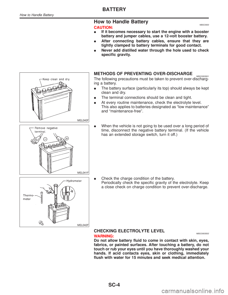
How to Handle BatteryNBSC0003CAUTION:
IIf it becomes necessary to start the engine with a booster
battery and jumper cables, use a 12-volt booster battery.
IAfter connecting battery cables, ensure that they are
tightly clamped to battery terminals for good contact.
INever add distilled water through the hole used to check
specific gravity.
MEL040F
METHODS OF PREVENTING OVER-DISCHARGENBSC0003S01The following precautions must be taken to prevent over-discharg-
ing a battery.
IThe battery surface (particularly its top) should always be kept
clean and dry.
IThe terminal connections should be clean and tight.
IAt every routine maintenance, check the electrolyte level.
This also applies to batteries designated as ªlow maintenanceº
and ªmaintenance-freeº.
MEL041F
IWhen the vehicle is not going to be used over a long period of
time, disconnect the negative battery terminal. (If the vehicle
has an extended storage switch, turn it off.)
MEL042F
ICheck the charge condition of the battery.
Periodically check the specific gravity of the electrolyte. Keep
a close check on charge condition to prevent over-discharge.
CHECKING ELECTROLYTE LEVELNBSC0003S02WARNING:
Do not allow battery fluid to come in contact with skin, eyes,
fabrics, or painted surfaces. After touching a battery, do not
touch or rub your eyes until you have thoroughly washed your
hands. If acid contacts eyes, skin or clothing, immediately
flush with water for 15 minutes and seek medical attention.
BATTERY
How to Handle Battery
SC-4
Page 2166 of 2395
DIAGNOSTIC PROCEDURE 1NBSC0019S03Check ªBº Terminal CircuitNBSC0019S0301
1 CHECK POWER SUPPLY FOR STARTER MOTOR ªBº TERMINAL
1. Remove the fuel pump fuse.
2. Crank or start the engine (where possible) until the fuel pressure is released.
3. Turn the ignition OFF.
4. Check that the starter motor terminal 1 connection is clean and tight.
5. Check voltage between starter motor terminal 1 and ground using a digital circuit tester.
SEL412X
OK or NG
OK©GO TO 2.
NG©Check harness between the battery and the starter motor for open circuit.
2 CHECK BATTERY CABLE CONNECTION QUALITY (VOLTAGE DROP TEST)
1. Check voltage between starter motor terminal 1 and battery positive terminal using a digital circuit tester.
SEL413X
OK or NG
OK©GO TO 3.
NG©Check harness between the battery and the starter motor for poor continuity.
GI
MA
EM
LC
EC
FE
AT
TF
PD
AX
SU
BR
ST
RS
BT
HA
EL
IDX
STARTING SYSTEM
Trouble Diagnoses with Battery/Starting/Charging System Tester (Cont'd)
SC-15
Page 2168 of 2395
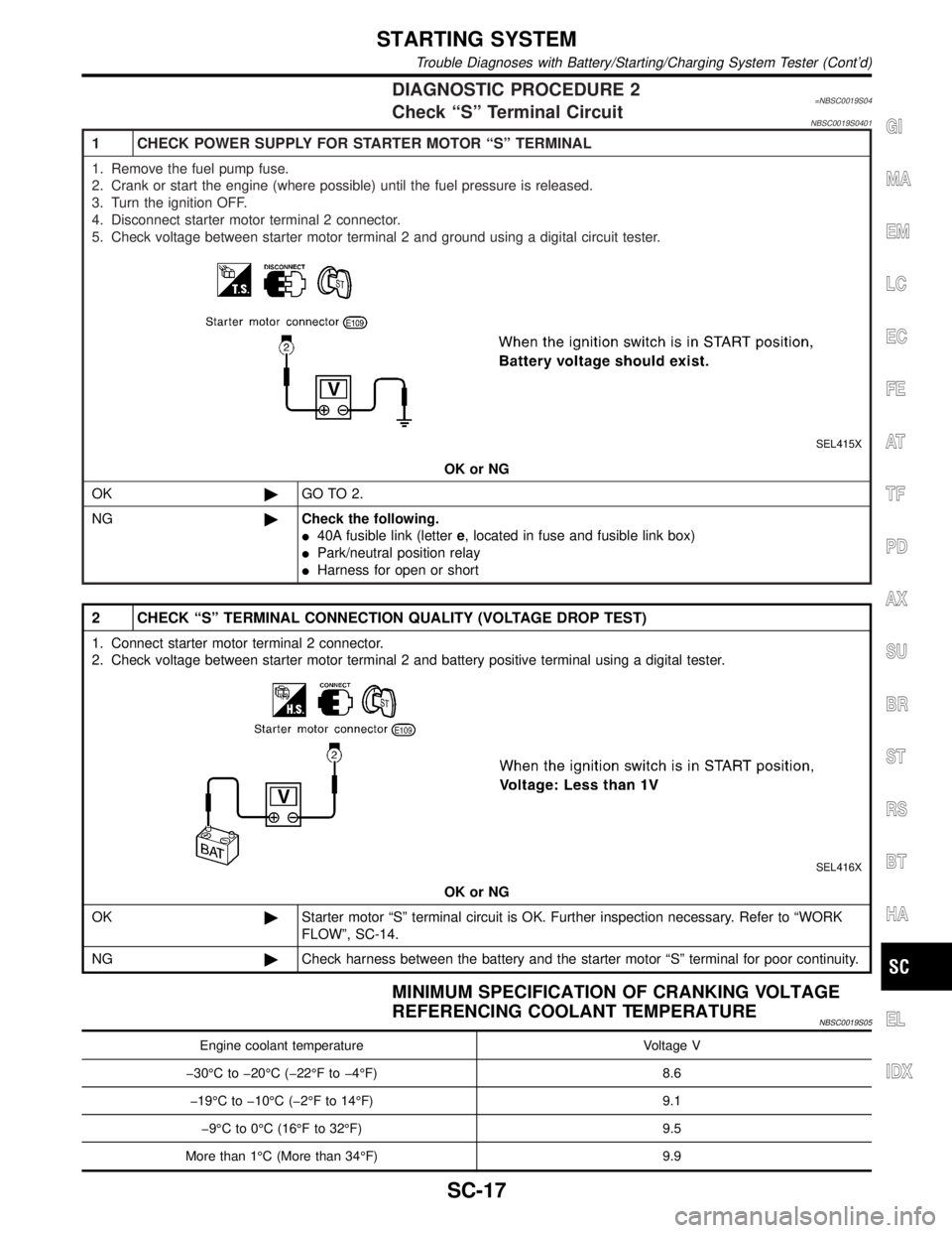
DIAGNOSTIC PROCEDURE 2=NBSC0019S04Check ªSº Terminal CircuitNBSC0019S0401
1 CHECK POWER SUPPLY FOR STARTER MOTOR ªSº TERMINAL
1. Remove the fuel pump fuse.
2. Crank or start the engine (where possible) until the fuel pressure is released.
3. Turn the ignition OFF.
4. Disconnect starter motor terminal 2 connector.
5. Check voltage between starter motor terminal 2 and ground using a digital circuit tester.
SEL415X
OK or NG
OK©GO TO 2.
NG©Check the following.
I40A fusible link (lettere, located in fuse and fusible link box)
IPark/neutral position relay
IHarness for open or short
2 CHECK ªSº TERMINAL CONNECTION QUALITY (VOLTAGE DROP TEST)
1. Connect starter motor terminal 2 connector.
2. Check voltage between starter motor terminal 2 and battery positive terminal using a digital tester.
SEL416X
OK or NG
OK©Starter motor ªSº terminal circuit is OK. Further inspection necessary. Refer to ªWORK
FLOWº, SC-14.
NG©Check harness between the battery and the starter motor ªSº terminal for poor continuity.
MINIMUM SPECIFICATION OF CRANKING VOLTAGE
REFERENCING COOLANT TEMPERATURE
NBSC0019S05
Engine coolant temperature Voltage V
þ30ÉC to þ20ÉC (þ22ÉF to þ4ÉF) 8.6
þ19ÉC to þ10ÉC (þ2ÉF to 14ÉF) 9.1
þ9ÉC to 0ÉC (16ÉF to 32ÉF) 9.5
More than 1ÉC (More than 34ÉF) 9.9
GI
MA
EM
LC
EC
FE
AT
TF
PD
AX
SU
BR
ST
RS
BT
HA
EL
IDX
STARTING SYSTEM
Trouble Diagnoses with Battery/Starting/Charging System Tester (Cont'd)
SC-17
Page 2172 of 2395

Trouble Diagnoses with
Battery/Starting/Charging System Tester
NBSC0020NOTE:
To ensure a complete and thorough diagnosis, the battery, starter
and alternator test segments must be done as a set from start to
finish.
SEL417X
1. Turn off all loads on the vehicle electrical system.
2. Perform battery and starting system test with Battery/Starting/
Charging system tester.
3. Press ªENTERº to begin the charging system test.
4. Start engine.
SEL418X
5. Press ªENTERº until ªLOADS OFF REV ENGINE 5 SECº is
displayed.
6. Raise and hold the engine speed at 1,500 to 2,000 rpm for
about 5 seconds, then return to the engine to idle.
Once the increase in engine rpm is detected, press ªENTERº
to continue.
NOTE:
IIf after 30 seconds an increase in engine idle speed is not
detected, ªRPM NOT DETECTEDº will display.
ISome engines may have a higher idle initially after starting,
particularly when the engine is cold. The tester may detect this
without any other action being taken. If this occurs, continue on
with the testing process. The final results will not be affected.
SEL419X
7. The tester now checks the engine at idle and performs the
DIODE/RIPPLE check.
8. When complete, the tester will prompt you to turn on the fol-
lowing electrical loads.
IHeater fun set to highest. Do not run the A/C or windshield
defroster.
IHeadlamp high beam
IRear window defogger
NOTE:
Do not run the windshield wipers or any other cyclical loads.
GI
MA
EM
LC
EC
FE
AT
TF
PD
AX
SU
BR
ST
RS
BT
HA
EL
IDX
CHARGING SYSTEM
Trouble Diagnoses with Battery/Starting/Charging System Tester
SC-21
Page 2189 of 2395
SST601C
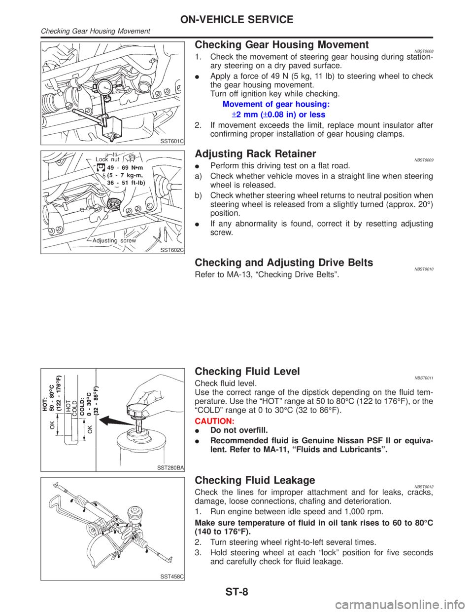
Checking Gear Housing MovementNBST00081. Check the movement of steering gear housing during station-
ary steering on a dry paved surface.
IApply a force of 49 N (5 kg, 11 lb) to steering wheel to check
the gear housing movement.
Turn off ignition key while checking.
Movement of gear housing:
±2mm(±0.08 in) or less
2. If movement exceeds the limit, replace mount insulator after
confirming proper installation of gear housing clamps.
SST602C
Adjusting Rack RetainerNBST0009IPerform this driving test on a flat road.
a) Check whether vehicle moves in a straight line when steering
wheel is released.
b) Check whether steering wheel returns to neutral position when
steering wheel is released from a slightly turned (approx. 20É)
position.
IIf any abnormality is found, correct it by resetting adjusting
screw.
Checking and Adjusting Drive BeltsNBST0010Refer to MA-13, ªChecking Drive Beltsº.
SST280BA
Checking Fluid LevelNBST0011Check fluid level.
Use the correct range of the dipstick depending on the fluid tem-
perature. Use the ªHOTº range at 50 to 80ÉC (122 to 176ÉF), or the
ªCOLDº range at 0 to 30ÉC (32 to 86ÉF).
CAUTION:
IDo not overfill.
IRecommended fluid is Genuine Nissan PSF II or equiva-
lent. Refer to MA-11, ªFluids and Lubricantsº.
SST458C
Checking Fluid LeakageNBST0012Check the lines for improper attachment and for leaks, cracks,
damage, loose connections, chafing and deterioration.
1. Run engine between idle speed and 1,000 rpm.
Make sure temperature of fluid in oil tank rises to 60 to 80ÉC
(140 to 176ÉF).
2. Turn steering wheel right-to-left several times.
3. Hold steering wheel at each ªlockº position for five seconds
and carefully check for fluid leakage.
ON-VEHICLE SERVICE
Checking Gear Housing Movement
ST-8
Page 2190 of 2395
CAUTION:
Do not hold the steering wheel in a locked position for more
than 15 seconds.
4. If fluid leakage at connectors is noticed, loosen flare nut and
then retighten.
Do not overtighten connector as this can damage O-ring,
washer and connector.
5. Check rack boots for accumulation of power steering fluid.
Bleeding Hydraulic SystemNBST00131. Raise front end of vehicle until wheels are clear of the ground.
2. Add fluid into oil tank to specified level. Then, quickly turn
steering wheel fully to right and left and lightly touch steering
stoppers.
Repeat steering wheel operation until fluid level no longer
decreases.
3. Start engine.
Repeat step 2 above.
IIncomplete air bleeding will cause the following to occur. When
this happens, bleed air again.
a) Air bubbles in reservoir tank
b) Clicking noise in oil pump
c) Excessive buzzing in oil pump
Fluid noise may occur in the valve or oil pump. This is common
when the vehicle is stationary or while turning steering wheel
slowly. This does not affect performance or durability of the system.
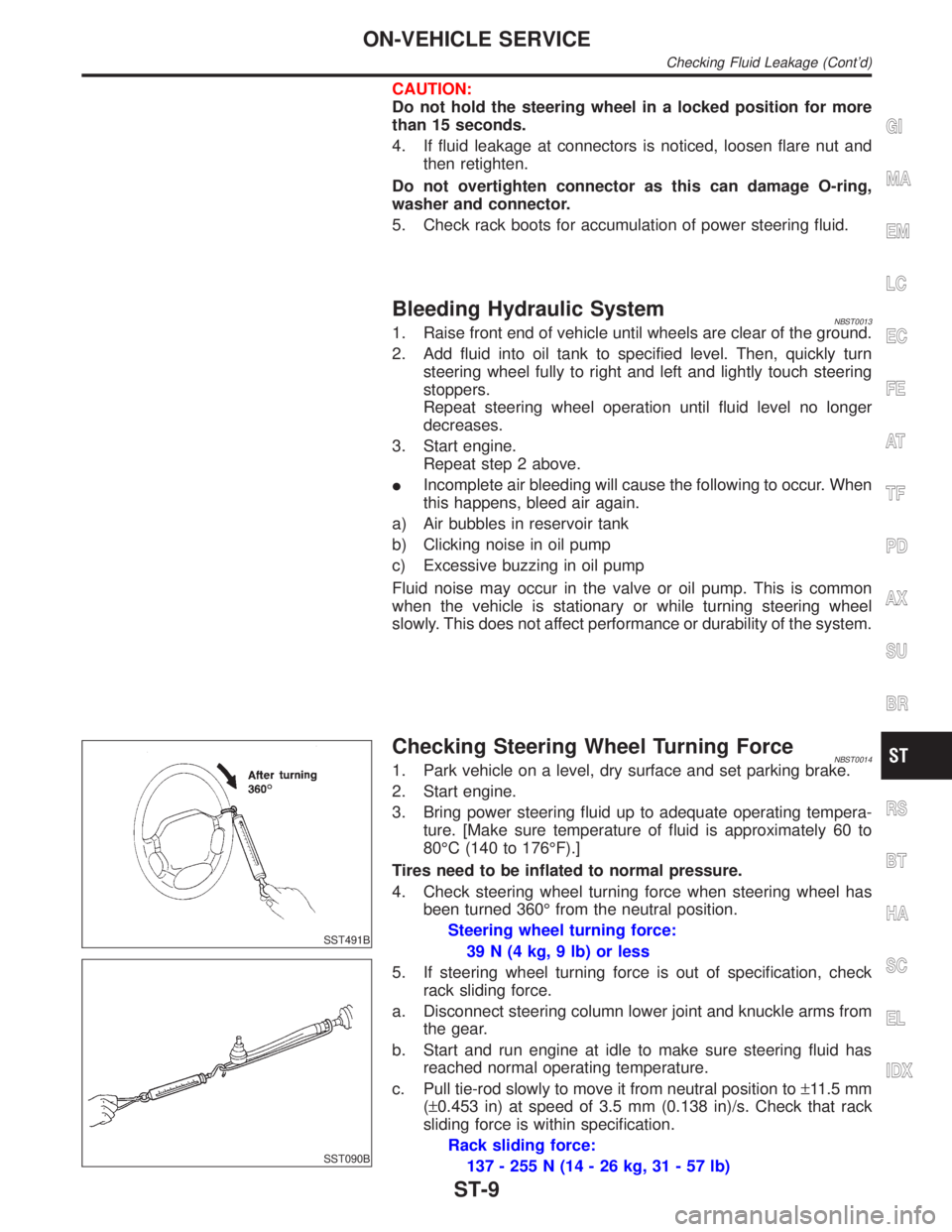
SST491B
SST090B
Checking Steering Wheel Turning ForceNBST00141. Park vehicle on a level, dry surface and set parking brake.
2. Start engine.
3. Bring power steering fluid up to adequate operating tempera-
ture. [Make sure temperature of fluid is approximately 60 to
80ÉC (140 to 176ÉF).]
Tires need to be inflated to normal pressure.
4. Check steering wheel turning force when steering wheel has
been turned 360É from the neutral position.
Steering wheel turning force:
39 N (4 kg, 9 lb) or less
5. If steering wheel turning force is out of specification, check
rack sliding force.
a. Disconnect steering column lower joint and knuckle arms from
the gear.
b. Start and run engine at idle to make sure steering fluid has
reached normal operating temperature.
c. Pull tie-rod slowly to move it from neutral position to±11.5 mm
(±0.453 in) at speed of 3.5 mm (0.138 in)/s. Check that rack
sliding force is within specification.
Rack sliding force:
137 - 255 N (14 - 26 kg, 31 - 57 lb)
GI
MA
EM
LC
EC
FE
AT
TF
PD
AX
SU
BR
RS
BT
HA
SC
EL
IDX
ON-VEHICLE SERVICE
Checking Fluid Leakage (Cont'd)
ST-9