Page 2016 of 2395

SMA211A
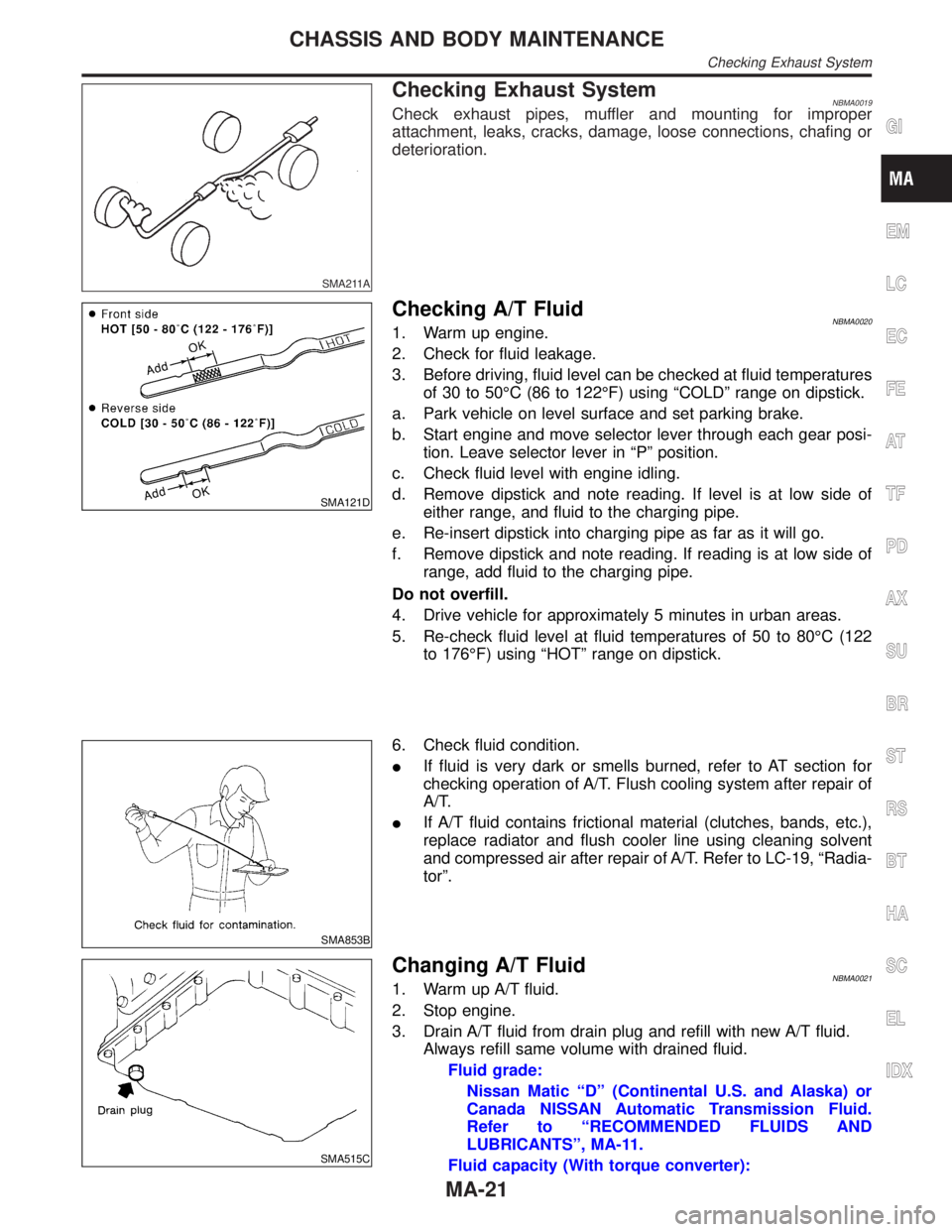
Checking Exhaust SystemNBMA0019Check exhaust pipes, muffler and mounting for improper
attachment, leaks, cracks, damage, loose connections, chafing or
deterioration.
SMA121D
Checking A/T FluidNBMA00201. Warm up engine.
2. Check for fluid leakage.
3. Before driving, fluid level can be checked at fluid temperatures
of 30 to 50ÉC (86 to 122ÉF) using ªCOLDº range on dipstick.
a. Park vehicle on level surface and set parking brake.
b. Start engine and move selector lever through each gear posi-
tion. Leave selector lever in ªPº position.
c. Check fluid level with engine idling.
d. Remove dipstick and note reading. If level is at low side of
either range, and fluid to the charging pipe.
e. Re-insert dipstick into charging pipe as far as it will go.
f. Remove dipstick and note reading. If reading is at low side of
range, add fluid to the charging pipe.
Do not overfill.
4. Drive vehicle for approximately 5 minutes in urban areas.
5. Re-check fluid level at fluid temperatures of 50 to 80ÉC (122
to 176ÉF) using ªHOTº range on dipstick.
SMA853B
6. Check fluid condition.
IIf fluid is very dark or smells burned, refer to AT section for
checking operation of A/T. Flush cooling system after repair of
A/T.
IIf A/T fluid contains frictional material (clutches, bands, etc.),
replace radiator and flush cooler line using cleaning solvent
and compressed air after repair of A/T. Refer to LC-19, ªRadia-
torº.
SMA515C
Changing A/T FluidNBMA00211. Warm up A/T fluid.
2. Stop engine.
3. Drain A/T fluid from drain plug and refill with new A/T fluid.
Always refill same volume with drained fluid.
Fluid grade:
Nissan Matic ªDº (Continental U.S. and Alaska) or
Canada NISSAN Automatic Transmission Fluid.
Refer to ªRECOMMENDED FLUIDS AND
LUBRICANTSº, MA-11.
Fluid capacity (With torque converter):
GI
EM
LC
EC
FE
AT
TF
PD
AX
SU
BR
ST
RS
BT
HA
SC
EL
IDX
CHASSIS AND BODY MAINTENANCE
Checking Exhaust System
MA-21
Page 2020 of 2395
SBR451D
Checking Brake Fluid Level and LeaksNBMA0030If fluid level is extremely low, check brake system for leaks.
SBR389C
Checking Brake Lines and CablesNBMA0031Check brake fluid lines and parking brake cables for improper
attachment, leaks, chafing, abrasions and deterioration.
SMA260A
Checking Disc BrakeNBMA0032ROTORNBMA0032S01Check condition and thickness.
Standard thickness:
28 mm (1.10 in)
Minimum thickness:
26 mm (1.02 in)
SMA922A
CALIPERNBMA0032S02Check for leakage.
SMA847B
PADNBMA0032S03Check wear or damage.
Standard thickness:
11 mm (0.43 in)
Minimum thickness:
2 mm (0.08 in)
GI
EM
LC
EC
FE
AT
TF
PD
AX
SU
BR
ST
RS
BT
HA
SC
EL
IDX
CHASSIS AND BODY MAINTENANCE
Checking Brake Fluid Level and Leaks
MA-25
Page 2097 of 2395

SEAT BELT RETRACTOR ON-VEHICLE CHECKNBRS0029S03Emergency Locking Retractors (ELR) and Automatic Locking Retractors (ALR)NBRS0029S0301NOTE:
All seat belt retractors are of the Emergency Locking Retractors (ELR) type. In an emergency (sudden stop)
the retractor will lock and prevent the belt from extending any further. All 3-point type seat belt retractors except
the driver's seat belt also have an Automatic Locking Retractors (ALR) mode. The ALR mode (also called child
restraint mode) is used when installing child seats. The ALR mode is activated when the seat belt is fully
extended. When the belt is then retracted partially, the ALR mode automatically locks the seat belt in a spe-
cific position so the belt cannot be extended any further. To cancel the ALR mode, allow the seat belt to fully
wind back into the retractor.
Check the seat belt retractors using the following test(s) to determine if a retractor assembly is operating
properly.
ELR Function Stationary CheckNBRS0029S0302Grasp the shoulder belt and pull forward quickly. The retractor should lock and prevent the belt from extend-
ing further.
ALR Function Stationary CheckNBRS0029S03041. Pull out entire length of seat belt from retractor until a click is heard.
2. Retract the belt partially. A clicking noise should be heard as the belt retracts indicating that the retractor
is in the Automatic Locking Retractors (ALR) mode.
3. Grasp the seat belt and try to pull out the retractor. The belt must lock and not extend any further. If NG,
replace the retractor assembly.
4. Allow the entire length of the belt to retract to cancel the automatic locking mode.
ELR Function Moving CheckNBRS0029S0303WARNING:
Perform the following test in a safe, open area clear of other vehicles and obstructions (for example,
a large, empty parking lot). Road surface must be paved and dry. DO NOT perform the following test
on wet or gravel roads or on public streets and highways. This could result in an accident and seri-
ous personal injury. The driver and passenger must be prepared to brace themselves in the event the
retractor does not lock.
1. Fasten driver's seat belt. Buckle a passenger into the seat for the belt that is to be tested.
2. Proceed to the designated safe area.
3. Drive the vehicle at approximately 16 km/h (10 MPH). Notify any passengers of a pending sudden stop
and the driver and passenger must be prepared to brace themselves in the event the retractor does not
lock, apply brakes firmly and make a very hard stop.
During stop, seat belts should lock and not be extended. If the seat belt retractor assembly does not lock,
perform the retractor off-vehicle check.
SEAT BELT RETRACTOR OFF-VEHICLE CHECKNBRS0029S041. Remove the seat belt retractor assembly.
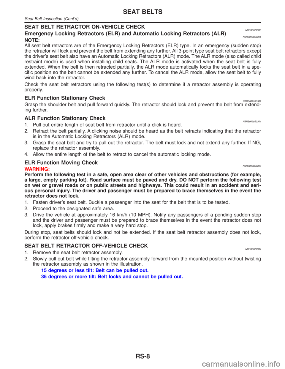
2. Slowly pull out belt while tilting the retractor assembly forward from the mounted position without twisting
the retractor assembly as shown in the illustration.
15 degrees or less tilt: Belt can be pulled out.
35 degrees or more tilt: Belt locks and cannot be pulled out.
SEAT BELTS
Seat Belt Inspection (Cont'd)
RS-8
Page 2190 of 2395

CAUTION:
Do not hold the steering wheel in a locked position for more
than 15 seconds.
4. If fluid leakage at connectors is noticed, loosen flare nut and
then retighten.
Do not overtighten connector as this can damage O-ring,
washer and connector.
5. Check rack boots for accumulation of power steering fluid.
Bleeding Hydraulic SystemNBST00131. Raise front end of vehicle until wheels are clear of the ground.
2. Add fluid into oil tank to specified level. Then, quickly turn
steering wheel fully to right and left and lightly touch steering
stoppers.
Repeat steering wheel operation until fluid level no longer
decreases.
3. Start engine.
Repeat step 2 above.
IIncomplete air bleeding will cause the following to occur. When
this happens, bleed air again.
a) Air bubbles in reservoir tank
b) Clicking noise in oil pump
c) Excessive buzzing in oil pump
Fluid noise may occur in the valve or oil pump. This is common
when the vehicle is stationary or while turning steering wheel
slowly. This does not affect performance or durability of the system.
SST491B
SST090B
Checking Steering Wheel Turning ForceNBST00141. Park vehicle on a level, dry surface and set parking brake.
2. Start engine.
3. Bring power steering fluid up to adequate operating tempera-
ture. [Make sure temperature of fluid is approximately 60 to
80ÉC (140 to 176ÉF).]
Tires need to be inflated to normal pressure.
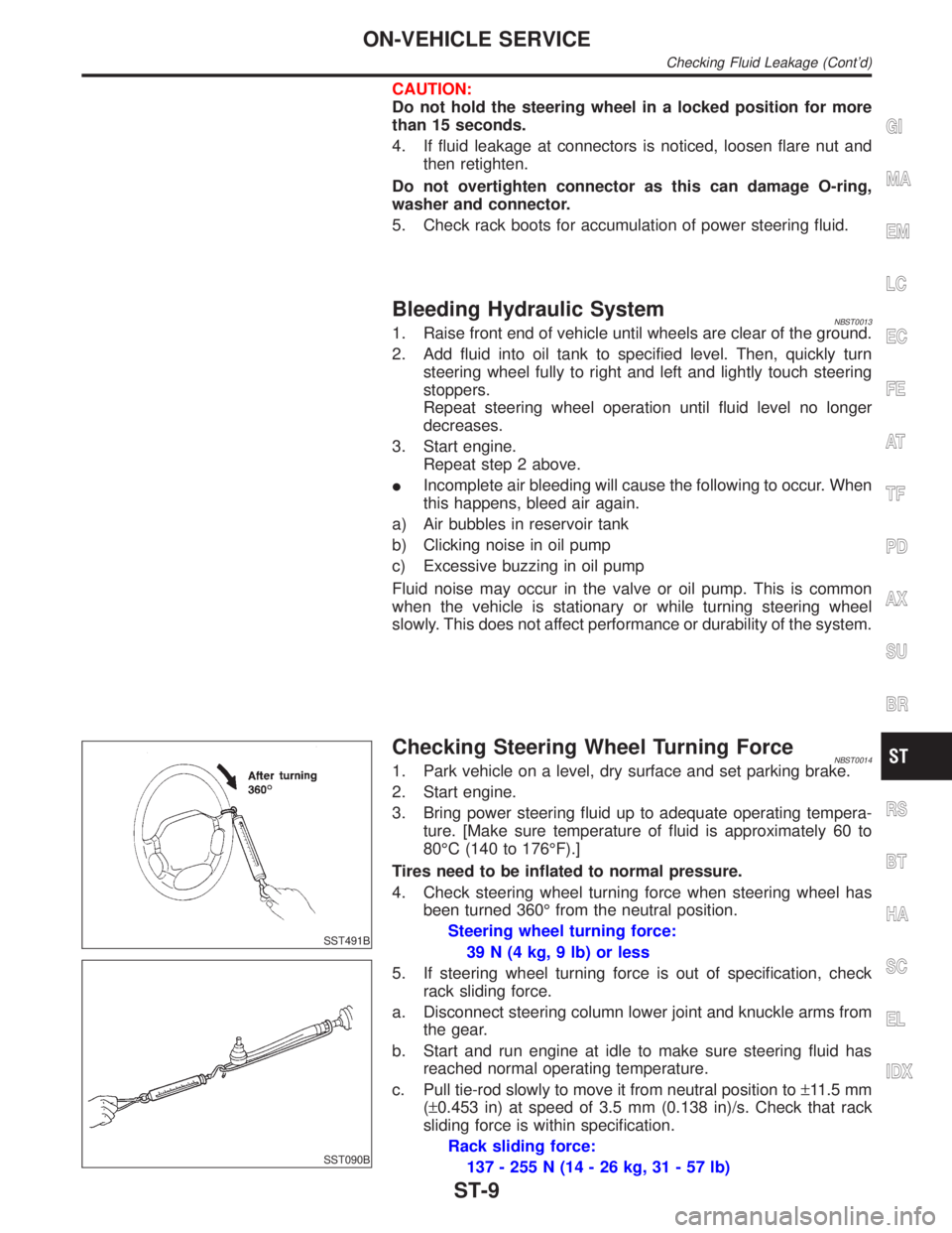
4. Check steering wheel turning force when steering wheel has
been turned 360É from the neutral position.
Steering wheel turning force:
39 N (4 kg, 9 lb) or less
5. If steering wheel turning force is out of specification, check
rack sliding force.
a. Disconnect steering column lower joint and knuckle arms from
the gear.
b. Start and run engine at idle to make sure steering fluid has
reached normal operating temperature.
c. Pull tie-rod slowly to move it from neutral position to±11.5 mm
(±0.453 in) at speed of 3.5 mm (0.138 in)/s. Check that rack
sliding force is within specification.
Rack sliding force:
137 - 255 N (14 - 26 kg, 31 - 57 lb)
GI
MA
EM
LC
EC
FE
AT
TF
PD
AX
SU
BR
RS
BT
HA
SC
EL
IDX
ON-VEHICLE SERVICE
Checking Fluid Leakage (Cont'd)
ST-9
Page 2232 of 2395
SBR686C
Removal and InstallationNBSU00261. Support axle and suspension components with a suitable jack
and block.
2. Disconnect brake hydraulic line and parking brake cables at
back plates.
CAUTION:
IUse flare nut wrench when removing and installing brake
tubes.
IBefore removing the rear suspension assembly, discon-
nect the ABS wheel sensor from the assembly. Then move
it away from the rear suspension assembly. Failure to do
so may result in damage to the sensor wires and the sen-
sor becoming inoperative.
3. Remove stabilizer bar from body.
4. Remove upper links and lower links from body.
5. Remove panhard rod from body.
6. Disconnect rear end of propeller shaft. Refer to PD-6,
ªRemoval and Installationº.
7. Remove upper end nuts of shock absorber.
SRA935
Final tightening for rubber parts requires to be carried out
under unladen condition with tires on ground.
GI
MA
EM
LC
EC
FE
AT
TF
PD
AX
BR
ST
RS
BT
HA
SC
EL
IDX
REAR SUSPENSION
Removal and Installation
SU-17