Page 420 of 2395
SBR042D
AdjustmentNBBR00471. Adjust clearance between shoe and drum as follows:
a. Release parking brake lever and loosen adjusting nut.
b. Depress brake pedal fully at least 10 times with engine run-
ning.
2. Pull control lever4-5notches. Then adjust control lever by
turning adjusting nut.
SBR073D
3. Pull control lever with specified amount of force. Check lever
stroke and ensure smooth operation.
Number of notches:6-8
4. Bend warning lamp switchplate to ensure:
IWarning lamp comes on when lever is lifted ªAº notches.
IWarning lamp goes out when lever is fully released.
Number of ªAº notches: 1 or less
GI
MA
EM
LC
EC
FE
AT
TF
PD
AX
SU
ST
RS
BT
HA
SC
EL
IDX
PARKING BRAKE CONTROL
Adjustment
BR-31
Page 473 of 2395
Parking Brake ControlNBBR0084Unit: notch
Control TypeCenter lever
Lever stroke
[under force of 196 N (20 kg, 44 lb)]6-8
Lever stroke when warning switch comes on 1 or less
SERVICE DATA AND SPECIFICATIONS (SDS)
Parking Brake Control
BR-84
Page 499 of 2395
SBT040A
Console finisher
1) Open the lid of the cup holders, insert a cloth-covered flat-
bladed screwdriver into the gap between the console and the
finisher, and remove the clip at the back.
2) Lift up the metal clip section, and pull forward to remove.
SBT033A
Console box
1) Pull up the parking brake lever.
2) Remove the screws, pull the console towards the back of the
car until it is free of the instrument panel, lift up the front and
remove.
IIt will be easier to remove if the parking brake lever is pulled
up for more than 10 notches.
SBT034A
Instrument finisher
Remove the screws and pull up.
SBT046A
Instrument lower panel on the passenger side
After removing the screws, hold both sides and pull out horizontally.
SBT047A
Instrument mask
Insert a cloth-covered flat-bladed screwdriver, and remove by lift-
ing up.
INSTRUMENT PANEL ASSEMBLY
Removal and Installation (Cont'd)
BT-26
Page 592 of 2395

SEF452Y
Idle Air Volume LearningNBEC0642
SEF454Y
SEF455Y
DESCRIPTIONNBEC0642S01ªIdle Air Volume Learningº is an operation to learn the idle air vol-
ume that keeps each engine within the specific range. It must be
performed under any of the following conditions:
IEach time IACV-AAC valve, throttle body or ECM is replaced.
IIdle speed or ignition timing is out of specification.
PRE-CONDITIONINGNBEC0642S02Before performing ªIdle Air Volume Learningº, make sure that all of
the following conditions are satisfied.
Learning will be cancelled if any of the following conditions are
missed for even a moment.
IBattery voltage: More than 12.9V (At idle)
IEngine coolant temperature: 70 - 99ÉC (158 - 210ÉF)
IPNP switch: ON
IElectric load switch: OFF
(Air conditioner, headlamp, rear window defogger)
On vehicles equipped with daytime running light systems, if
the parking brake is applied before the engine is started the
headlamp will not illuminate.
ICooling fan motor: Not operating
ISteering wheel: Neutral (Straight-ahead position)
IVehicle speed: Stopped
ITransmission: Warmed-up
For A/T models with CONSULT-II, drive vehicle until ªFLUID
TEMP SEº in ªDATA MONITORº mode of ªA/Tº system indi-
cates less than 0.9V.
For A/T models without CONSULT-II, drive vehicle for 10 min-
utes.
OPERATION PROCEDURENBEC0642S03With CONSULT-IINBEC0642S03011. Turn ignition switch ªONº and wait at least 1 second.
2. Turn ignition switch ªOFFº and wait at least 10 seconds.
3. Start engine and warm it up to normal operating temperature.
4. Check that all items listed under the topic ªPRE-CONDITION-
INGº (previously mentioned) are in good order.
5. Turn ignition switch ªOFFº and wait at least 10 seconds.
6. Start the engine and let it idle for at least 30 seconds.
7. Select ªIDLE AIR VOL LEARNº in ªWORK SUPPORTº mode.
8. Touch ªSTARTº and wait 20 seconds.
9. Make sure that ªCMPLTº is displayed on CONSULT-II screen.
If ªINCMPº is displayed, ªIdle Air Volume Learningº will not be
carried out successfully. In this case, find the cause of the
problem by referring to the NOTE below.
10. Rev up the engine two or three times. Make sure that idle
speed and ignition timing are within specifications.
ITEM SPECIFICATION
Idle speed 750±50 rpm (in ªPº or ªNº position)
Ignition timing 15ɱ5É BTDC (in ªPº or ªNº position)
GI
MA
EM
LC
FE
AT
TF
PD
AX
SU
BR
ST
RS
BT
HA
SC
EL
IDX
BASIC SERVICE PROCEDURE
Idle Air Volume Learning
EC-57
Page 1231 of 2395

Component Parts and Harness Connector
Location
NBEL0161
SEL460X
System DescriptionNBEL0192The headlamp system for Canada vehicles contains a daytime light control unit that activates the high beam
headlamps at approximately half illumination whenever the engine is running. If the parking brake is applied
before the engine is started the daytime lights will not be illuminated. The daytime lights will illuminate once
the parking brake is released. Thereafter, the daytime lights will continue to operate when the parking brake
is applied.
And battery saver system is controlled by the headlamp battery saver control unit and smart entrance control
unit.
Power is supplied at all times
Ito headlamp LH relay terminals 1 and 3
Ithrough 15A fuse (No. 60, located in the fuse and fusible link box), and
Ito headlamp LH relay terminal 6
Ithrough 20A fuse (No. 32, located in the fuse and fusible link box), and
Ito headlamp RH relay terminals 1 and 3
Ithrough 15A fuse (No. 59, located in the fuse and fusible link box), and
Ito headlamp RH relay terminal 6
Ithrough 20A fuse (No. 31, located in the fuse and fusible link box), and
Ito headlamp battery saver control unit terminal 7, and
Ito smart entrance control unit terminal 10
Ithrough 7.5A fuse [No. 24, located in the fuse block (J/B)].
Ground is supplied
Ito daytime light control unit terminal 16,
Ito auto light control unit terminal 5 and
Ito headlamp battery saver control unit terminals 4 and 11.
When the ignition switch is in the ON or START position, power is also supplied
HEADLAMP (FOR CANADA) Ð DAYTIME LIGHT SYSTEM Ð
Component Parts and Harness Connector Location
EL-46
Page 1233 of 2395

BATTERY SAVER CONTROLNBEL0192S02When the ignition switch is turned from ON (or START) to OFF (or ACC) positions while headlamps are
illuminated, The RAP signal is supplied to terminal 10 of the headlamp battery saver control unit from smart
entrance control unit terminal 5.
After counting 45 seconds by the RAP signal from the smart entrance control unit to headlamp battery saver
control unit, the ground supply to terminal 2 of headlamp LH and RH relays from headlamp battery saver con-
trol unit terminals 2 and 8 is terminated.
Then headlamps are turned off.
The headlamps are turned off when LH or RH door is opened even if 45 seconds have not passed after the
ignition switch is turned from ON (or START) to OFF (or ACC) positions while headlamps are illuminated.
When the lighting switch is turned from OFF to 2ND after headlamps are turned to off by the battery saver
control, ground is supply
Ito headlamp battery saver control unit terminals 5 and 13 from lighting switch terminal 11, and
Ito headlamp LH and RH relays terminal 2 from headlamp battery saver control unit terminals 2 and 8
Ithrough headlamp battery saver control unit terminals 3 and 9, and
Ithrough lighting switch terminal 12.
Then headlamps illuminate again.
AUTO LIGHT OPERATIONNBEL0192S03For auto light operation, refer to ªHEADLAMPº (EL-33).
DAYTIME LIGHT OPERATIONNBEL0192S04With the engine running, the lighting switch in the OFF or 1ST position and parking brake released, power is
supplied
Ithrough daytime light control unit terminals 3 and 7
Ito terminal 1 of RH headlamp
Ithrough terminal 2 of RH headlamp
Ito daytime light control unit terminal 9
Ithrough daytime light control unit terminal 6
Ito terminal 1 of LH headlamp.
Ground is supplied to terminal 2 of LH headlamp.
Ithrough daytime light control unit terminals 10 and 16
Ithrough body grounds E13 and E41.
Because the high beam headlamps are now wired in series, they operate at half illumination.
HEADLAMP (FOR CANADA) Ð DAYTIME LIGHT SYSTEM Ð
System Description (Cont'd)
EL-48
Page 1234 of 2395

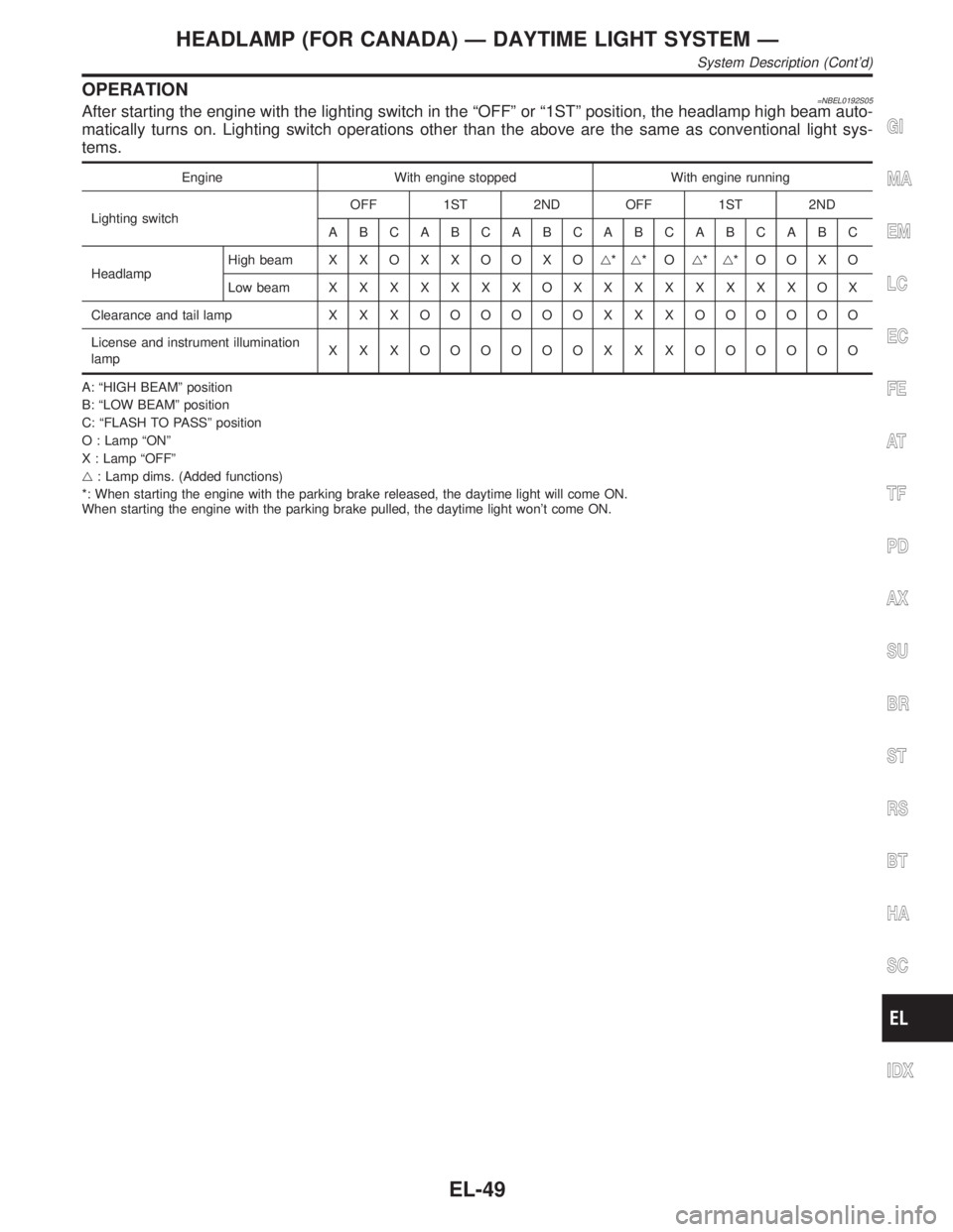
OPERATION=NBEL0192S05After starting the engine with the lighting switch in the ªOFFº or ª1STº position, the headlamp high beam auto-
matically turns on. Lighting switch operations other than the above are the same as conventional light sys-
tems.
Engine With engine stopped With engine running
Lighting switchOFF 1ST 2ND OFF 1ST 2ND
ABCABCABCABCABCABC
HeadlampHigh beam X X O X X O O X Og*g*Og*g*OOXO
Low beamXXXXXXXOXXXXXXXXOX
Clearance and tail lamp X X XOOOOOO X X X OOOOOO
License and instrument illumination
lampX X X OOOOOO X X X OOOOOO
A: ªHIGH BEAMº position
B: ªLOW BEAMº position
C: ªFLASH TO PASSº position
O : Lamp ªONº
X : Lamp ªOFFº
g: Lamp dims. (Added functions)
*: When starting the engine with the parking brake released, the daytime light will come ON.
When starting the engine with the parking brake pulled, the daytime light won't come ON.
GI
MA
EM
LC
EC
FE
AT
TF
PD
AX
SU
BR
ST
RS
BT
HA
SC
IDX
HEADLAMP (FOR CANADA) Ð DAYTIME LIGHT SYSTEM Ð
System Description (Cont'd)
EL-49
Page 1241 of 2395

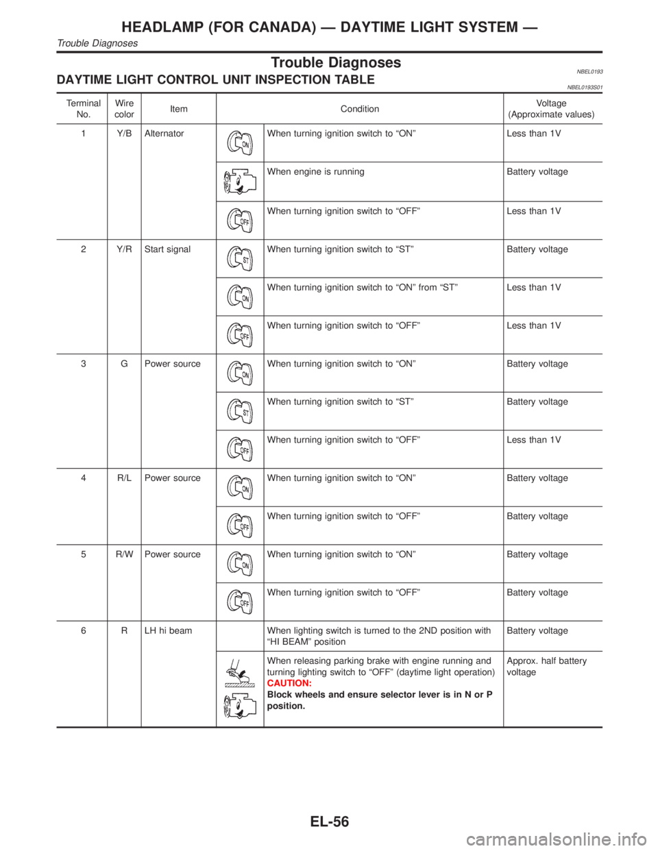
Trouble DiagnosesNBEL0193DAYTIME LIGHT CONTROL UNIT INSPECTION TABLENBEL0193S01
Terminal
No.Wire
colorItem ConditionVoltage
(Approximate values)
1 Y/B Alternator
When turning ignition switch to ªONº Less than 1V
When engine is running Battery voltage
When turning ignition switch to ªOFFº Less than 1V
2 Y/R Start signal
When turning ignition switch to ªSTº Battery voltage
When turning ignition switch to ªONº from ªSTº Less than 1V
When turning ignition switch to ªOFFº Less than 1V
3 G Power source
When turning ignition switch to ªONº Battery voltage
When turning ignition switch to ªSTº Battery voltage
When turning ignition switch to ªOFFº Less than 1V
4 R/L Power source
When turning ignition switch to ªONº Battery voltage
When turning ignition switch to ªOFFº Battery voltage
5 R/W Power source
When turning ignition switch to ªONº Battery voltage
When turning ignition switch to ªOFFº Battery voltage
6 R LH hi beam When lighting switch is turned to the 2ND position with
ªHI BEAMº positionBattery voltage
When releasing parking brake with engine running and
turning lighting switch to ªOFFº (daytime light operation)
CAUTION:
Block wheels and ensure selector lever is in N or P
position.Approx. half battery
voltage
HEADLAMP (FOR CANADA) Ð DAYTIME LIGHT SYSTEM Ð
Trouble Diagnoses
EL-56