2001 INFINITI QX4 heater
[x] Cancel search: heaterPage 1026 of 2395
On Board Diagnosis LogicNBEC0282HThe closed loop control has the one trip detection logic.
Malfunction is detected when the closed loop control function for
right bank does not operate even when vehicle is driving in the
specified condition, the closed loop control function for left bank
does not operate even when vehicle is driving in the specified
condition.
Possible CauseNBEC0531IThe front heated oxygen sensor circuit is open or shorted.
IHeated oxygen sensor 1 (front)
IHeated oxygen sensor 1 heater (front)
DTC Confirmation ProcedureNBEC0283CAUTION:
Always drive vehicle at a safe speed.
NOTE:
If ªDTC Confirmation Procedureº has been previously conducted,
always turn ignition switch ªOFFº and wait at least 10 seconds
before conducting the next test.
TESTING CONDITION:
INever raise engine speed above 3,600 rpm during the
ªDTC Confirmation Procedureº. If the engine speed limit is
exceeded, retry the procedure from step 2.
IBefore performing the following procedure, confirm that
battery voltage is more than 11V at idle.
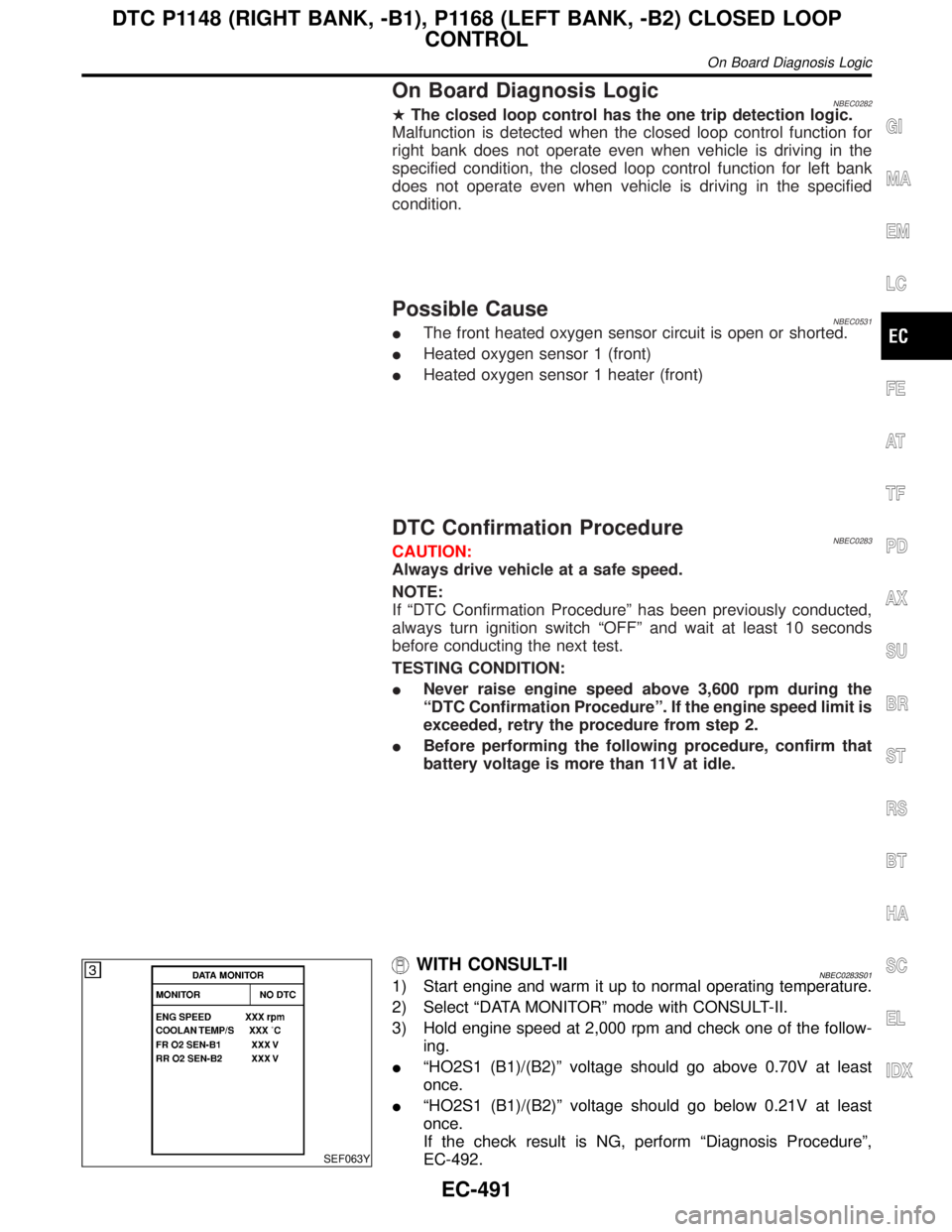
SEF063Y
WITH CONSULT-IINBEC0283S011) Start engine and warm it up to normal operating temperature.
2) Select ªDATA MONITORº mode with CONSULT-II.
3) Hold engine speed at 2,000 rpm and check one of the follow-
ing.
IªHO2S1 (B1)/(B2)º voltage should go above 0.70V at least
once.
IªHO2S1 (B1)/(B2)º voltage should go below 0.21V at least
once.
If the check result is NG, perform ªDiagnosis Procedureº,
EC-492.
GI
MA
EM
LC
FE
AT
TF
PD
AX
SU
BR
ST
RS
BT
HA
SC
EL
IDX
DTC P1148 (RIGHT BANK, -B1), P1168 (LEFT BANK, -B2) CLOSED LOOP
CONTROL
On Board Diagnosis Logic
EC-491
Page 1184 of 2395
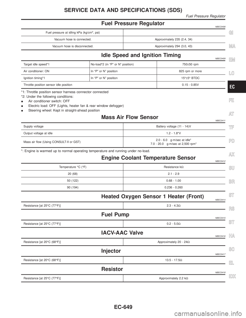
Fuel Pressure RegulatorNBEC0408
Fuel pressure at idling kPa (kg/cm2, psi)
Vacuum hose is connected. Approximately 235 (2.4, 34)
Vacuum hose is disconnected. Approximately 294 (3.0, 43)
Idle Speed and Ignition TimingNBEC0409
Target idle speed*1 No-load*2 (in ªPº or Nº position) 750±50 rpm
Air conditioner: ON In ªPº or Nº position 825 rpm or more
Ignition timing*1 In ªPº or Nº position 15ɱ5É BTDC
Throttle position sensor idle position0.15 - 0.85V
*1: Throttle position sensor harness connector connected
*2: Under the following conditions:
IAir conditioner switch: OFF
IElectric load: OFF (Lights, heater fan & rear window defogger)
ISteering wheel: Kept in straight-ahead position
Mass Air Flow SensorNBEC0411
Supply voltageBattery voltage (11 - 14)V
Output voltage at idle1.2 - 1.8*V
Mass air flow (Using CONSULT-II or GST)2.0 - 6.0 g´m/sec at idle*
7.0 - 20.0 g´m/sec at 2,500 rpm*
*: Engine is warmed up to normal operating temperature and running under no-load.
Engine Coolant Temperature SensorNBEC0412
Temperature ÉC (ÉF) Resistance kW
20 (68) 2.1 - 2.9
50 (122) 0.68 - 1.00
90 (194) 0.236 - 0.260
Heated Oxygen Sensor 1 Heater (Front)NBEC0414
Resistance [at 25ÉC (77ÉF)]2.3 - 4.3W
Fuel PumpNBEC0415
Resistance [at 25ÉC (77ÉF)]0.2 - 5.0W
IACV-AAC ValveNBEC0416
Resistance [at 20ÉC (68ÉF)]Approximately 20 - 24W
InjectorNBEC0417
Resistance [at 20ÉC (68ÉF)]13.5 - 17.5W
ResistorNBEC0418
Resistance [at 25ÉC (77ÉF)]Approximately 2.2 kW
GI
MA
EM
LC
FE
AT
TF
PD
AX
SU
BR
ST
RS
BT
HA
SC
EL
IDX
SERVICE DATA AND SPECIFICATIONS (SDS)
Fuel Pressure Regulator
EC-649
Page 1185 of 2395
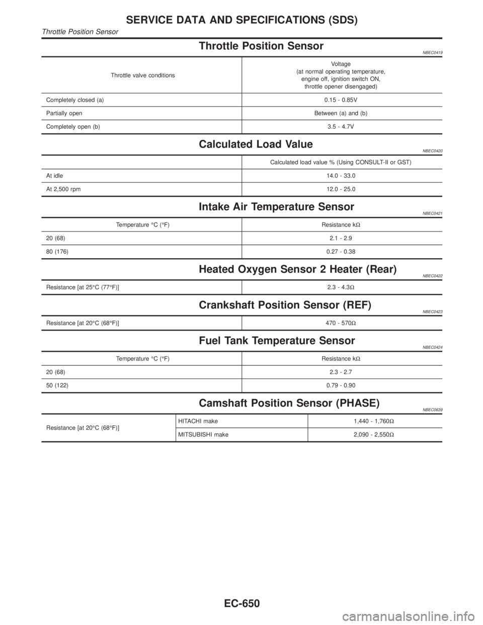
Throttle Position SensorNBEC0419
Throttle valve conditionsVoltage
(at normal operating temperature,
engine off, ignition switch ON,
throttle opener disengaged)
Completely closed (a)0.15 - 0.85V
Partially openBetween (a) and (b)
Completely open (b)3.5 - 4.7V
Calculated Load ValueNBEC0420
Calculated load value % (Using CONSULT-II or GST)
At idle14.0 - 33.0
At 2,500 rpm12.0 - 25.0
Intake Air Temperature SensorNBEC0421
Temperature ÉC (ÉF) Resistance kW
20 (68)2.1 - 2.9
80 (176)0.27 - 0.38
Heated Oxygen Sensor 2 Heater (Rear)NBEC0422
Resistance [at 25ÉC (77ÉF)]2.3 - 4.3W
Crankshaft Position Sensor (REF)NBEC0423
Resistance [at 20ÉC (68ÉF)]470 - 570W
Fuel Tank Temperature SensorNBEC0424
Temperature ÉC (ÉF) Resistance kW
20 (68)2.3 - 2.7
50 (122)0.79 - 0.90
Camshaft Position Sensor (PHASE)NBEC0639
Resistance [at 20ÉC (68ÉF)]HITACHI make 1,440 - 1,760W
MITSUBISHI make 2,090 - 2,550W
SERVICE DATA AND SPECIFICATIONS (SDS)
Throttle Position Sensor
EC-650
Page 1643 of 2395
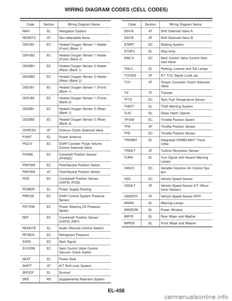
Code Section Wiring Diagram Name
NAVI EL Navigation System
NONDTC AT Non-detectable Items
O2H1B1 EC Heated Oxygen Sensor 1 Heater
(Front) (Bank 1)
O2H1B2 EC Heated Oxygen Sensor 1 Heater
(Front) (Bank 2)
O2H2B1 EC Heated Oxygen Sensor 2 Heater
(Rear) (Bank 1)
O2H2B2 EC Heated Oxygen Sensor 2 Heater
(Rear) (Bank 2)
O2S1B1 EC Heated Oxygen Sensor 1 (Front)
(Bank 1)
O2S1B2 EC Heated Oxygen Sensor 1 (Front)
(Bank 2)
O2S2B1 EC Heated Oxygen Sensor 2 (Rear)
(Bank 1)
O2S2B2 EC Heated Oxygen Sensor 2 (Rear)
(Bank 2)
OVRCSV AT Overrun Clutch Solenoid Valve
P/ANT EL Power Antenna
PGC/V EC EVAP Canister Purge Volume
Control Solenoid Valve
PHASE EC Camshaft Position Sensor
(PHASE)
PNP/SW EC Park/Neutral Position Switch
PNP/SW AT Park/Neutral Position Switch
POS EC Crankshaft Position Sensor
(CKPS) (POS)
POWER EL Power Supply Routing
PRE/SE EC EVAP Control System Pressure
Sensor
PST/SW EC Power Steering Oil Pressure
Switch
REF EC Crankshaft Position Sensor
(CKPS) (REF)
REMOTE EL Audio (Remote Control Switch)
RP/SEN EC Refrigerant Pressure
S/SIG EC Start Signal
S/VCSW EC Swirl Control Valve Control
Vacuum Check Switch
SEAT EL Power Seat
SHIFT AT A/T Shift Lock System
SROOF EL Sunroof
SRS RS Supplemental Restraint SystemCode Section Wiring Diagram Name
SSV/A AT Shift Solenoid Valve A
SSV/B AT Shift Solenoid Valve B
START SC Starting System
STOP/L EL Stop lamp
SWL/V EC Swirl Control Valve Control Sole-
noid Valve
TAIL/L EL Parking, License and Tail Lamps
TCCSIG AT A/T TCC Signal (Lock up)
TCV AT Torque Converter Clutch Solenoid
Valve
T/F TF Transfer
TFTS EC Tank Fuel Temperature Sensor
THEFT EL Theft Warning System
TLID EL Glass Hatch Opener
TP/SW EC Throttle Position Switch
TPS AT Throttle Position Sensor
TPS EC Throttle Position Sensor
TRNSMT EL Integrated HOMELINKYTrans-
mitter
TRSA/T AT Turbine Revolution Sensor
TURN EL Turn Signal and Hazard Warning
Lamps
VIAS/V EC Variable Induction Air Control Sys-
tem
VSS EC Vehicle Speed Sensor
VSSA/T AT Vehicle Speed Sensor A/T (Revo-
lution Sensor)
VSSMTR AT Vehicle Speed Sensor MTR
WARN EL Warning Lamps
WINDOW EL Power Window
WIP/R EL Rear Wiper and Washer
WIPER EL Front Wiper and Washer
WIRING DIAGRAM CODES (CELL CODES)
EL-458
Page 1644 of 2395
ENGINE MECHANICAL
SECTION
EM
CONTENTS
PRECAUTIONS...............................................................3
Parts Requiring Angular Tightening .............................3
Liquid Gasket Application Procedure ..........................3
PREPARATION...............................................................4
Special Service Tools ..................................................4
Commercial Service Tools ...........................................6
NOISE, VIBRATION AND HARSHNESS (NVH)
TROUBLESHOOTING.....................................................8
NVH Troubleshooting - Engine Noise .........................9
OUTER COMPONENT PARTS.....................................10
Removal and Installation ...........................................10
TIGHTENING PROCEDURES...................................12
MEASUREMENT OF COMPRESSION PRESSURE....14
OIL PAN.........................................................................15
Components...............................................................15
Removal .....................................................................15
Installation ..................................................................18
TIMING CHAIN..............................................................20
Components...............................................................20
POSITION FOR APPLYING LIQUID GASKET............21
Removal .....................................................................23
Inspection...................................................................29
Installation ..................................................................29
OIL SEAL.......................................................................35
Replacement ..............................................................35
VALVE OIL SEAL.....................................................35
OIL SEAL INSTALLATION DIRECTION.....................36
FRONT OIL SEAL....................................................36
REAR OIL SEAL......................................................36
CYLINDER HEAD..........................................................38
Components...............................................................38
Removal .....................................................................39
Disassembly...............................................................41
Inspection...................................................................42
CYLINDER HEAD DISTORTION...............................42
CAMSHAFT VISUAL CHECK....................................42
CAMSHAFT RUNOUT..............................................42
CAMSHAFT CAM HEIGHT.......................................42
CAMSHAFT JOURNAL CLEARANCE........................42
CAMSHAFT END PLAY............................................43
CAMSHAFT SPROCKET RUNOUT...........................43
VALVE GUIDE CLEARANCE....................................43
VALVE GUIDE REPLACEMENT................................44
VALVE SEATS.........................................................45
REPLACING VALVE SEAT FOR SERVICE PARTS....45
VALVE DIMENSIONS...............................................46
VALVE SPRING.......................................................46
VALVE LIFTER........................................................46
Assembly ...................................................................47
Installation ..................................................................47
Valve Clearance.........................................................52
CHECKING.............................................................52
ADJUSTING............................................................54
ENGINE ASSEMBLY.....................................................57
Removal and Installation ...........................................57
REMOVAL...............................................................58
INSTALLATION........................................................60
CYLINDER BLOCK.......................................................61
Components...............................................................61
CYLINDER BLOCK HEATER....................................62
Removal and Installation ...........................................62
Disassembly...............................................................62
PISTON, CRANKSHAFT AND OIL JET......................62
Inspection...................................................................63
PISTON AND PISTON PIN CLEARANCE..................63
PISTON RING SIDE CLEARANCE............................64
PISTON RING END GAP..........................................64
CONNECTING ROD BEND AND TORSION...............65
CYLINDER BLOCK DISTORTION AND WEAR...........65
PISTON-TO-BORE CLEARANCE..............................66
CRANKSHAFT.........................................................67
BEARING CLEARANCE...........................................67
CONNECTING ROD BUSHING CLEARANCE
(SMALL END)
..........................................................70
DRIVE PLATE RUNOUT..........................................70
Assembly ...................................................................71
PISTON..................................................................71
OIL JET..................................................................71
CRANKSHAFT.........................................................71
REPLACEMENT OF PILOT CONVERTER.................74
DRIVE PLATE.........................................................74
GI
MA
LC
EC
FE
AT
TF
PD
AX
SU
BR
ST
RS
BT
HA
SC
EL
IDX
Page 1702 of 2395

Rear Engine MountingNBEM0042S0102
SEM459G
SEM605G
SEM461G
SEM324F
1. Release fuel pressure.
Refer to EC-39, ªFuel pressure releaseº.
2. Remove engine hood and front RH and LH wheels.
3. Remove engine undercover and suspension member stay.
4. Drain coolant from radiator.
5. Remove the following parts.
IRadiator shroud
IRadiator
ICooling fan
IDrive belts
IBattery
IEngine cover
IThrottle wires
6. Air duct with air cleaner case.
7. Disconnect vacuum hoses, fuel hoses, heater hoses, EVAP
canister hoses, harnesses, connectors and so on.
8. Remove air conditioner compressor from bracket, then put it
aside holding with a suitable wire.
9. Remove power steering oil pump and reservoir tank with
bracket, then put it aside holding with a suitable wire.
10. Remove alternator.
11. Remove exhaust front tube heat insulators, then remove rear
heated oxygen sensors.
12. Remove exhaust front and rear tubes.
Refer to FE-8, ªRemoval and Installationº.
13. Remove transmission with transfer.
Refer to AT-277, ªRemovalº.
14. Remove TWC (manifold) heat insulators, then remove TWC
(manifold).
15. Install engine slingers.
16. Hoist engine with engine slingers and remove front engine
mounting nuts.
GI
MA
LC
EC
FE
AT
TF
PD
AX
SU
BR
ST
RS
BT
HA
SC
EL
IDX
ENGINE ASSEMBLY
Removal and Installation (Cont'd)
EM-59
Page 1705 of 2395
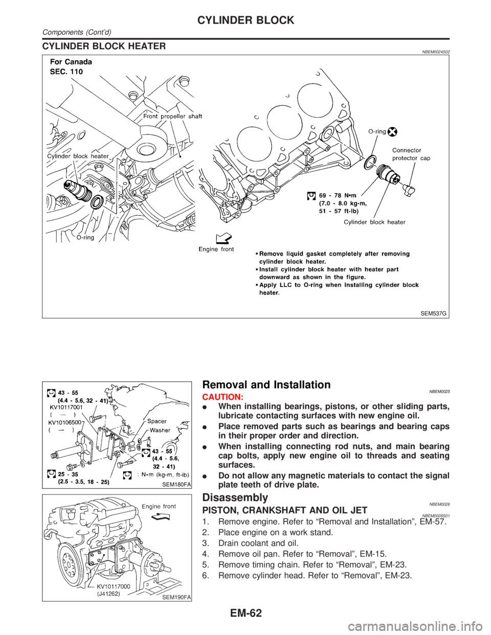
CYLINDER BLOCK HEATERNBEM0024S02
SEM537G
SEM180FA
Removal and InstallationNBEM0025CAUTION:
IWhen installing bearings, pistons, or other sliding parts,
lubricate contacting surfaces with new engine oil.
IPlace removed parts such as bearings and bearing caps
in their proper order and direction.
IWhen installing connecting rod nuts, and main bearing
cap bolts, apply new engine oil to threads and seating
surfaces.
IDo not allow any magnetic materials to contact the signal
plate teeth of drive plate.
SEM190FA
DisassemblyNBEM0026PISTON, CRANKSHAFT AND OIL JETNBEM0026S011. Remove engine. Refer to ªRemoval and Installationº, EM-57.
2. Place engine on a work stand.
3. Drain coolant and oil.
4. Remove oil pan. Refer to ªRemovalº, EM-15.
5. Remove timing chain. Refer to ªRemovalº, EM-23.
6. Remove cylinder head. Refer to ªRemovalº, EM-23.
CYLINDER BLOCK
Components (Cont'd)
EM-62
Page 1753 of 2395
PRECAUTIONS FOR ENGINE OILSNBGI0001S05Prolonged and repeated contact with used engine oil may cause
skin cancer. Try to avoid direct skin contact with used oil.
If skin contact is made, wash thoroughly with soap or hand cleaner
as soon as possible.
Health Protection PrecautionsNBGI0001S0501IAvoid prolonged and repeated contact with oils, particularly
used engine oils.
IWear protective clothing, including impervious gloves where
practicable.
IDo not put oily rags in pockets.
IAvoid contaminating clothes, particularly underpants, with oil.
IHeavily soiled clothing and oil-impregnated footwear should
not be worn. Overalls must be cleaned regularly.
IFirst Aid treatment should be obtained immediately for open
cuts and wounds.
IUse barrier creams, applying them before each work period, to
help the removal of oil from the skin.
IWash with soap and water to ensure all oil is removed (skin
cleansers and nail brushes will help). Preparations containing
lanolin replace the natural skin oils which have been removed.
IDo not use gasoline, kerosine, diesel fuel, gas oil, thinners or
solvents for cleaning skin.
IIf skin disorders develop, obtain medical advice without delay.
IWhere practicable, degrease components prior to handling.
IWhere there is a risk of eye contact, eye protection should be
worn, for example, chemical goggles or face shields; in addi-
tion an eye wash facility should be provided.
Environmental Protection PrecautionsNBGI0001S0502Burning used engine oil in small space heaters or boilers can be
recommended only for units of approved design. The heating sys-
tem must meet the requirements of HM Inspectorate of Pollution for
small burners of less than 0.4 MW. If in doubt check with the
appropriate local authority and/or manufacturer of the approved
appliance.
Dispose of used oil and used oil filters through authorized waste
disposal contractors to licensed waste disposal sites, or to the
waste oil reclamation trade. If in doubt, contact the local authority
for advice on disposal facilities.
It is illegal to pour used oil on to the ground, down sewers or drains,
or into water courses.
The regulations concerning pollution vary between regions.
PRECAUTIONS FOR FUELNBGI0001S06Use unleaded gasoline with an octane rating of at least 87 AKI
(Anti-Knock Index) number (research octane number 91).
CAUTION:
Do not use leaded gasoline. Using leaded gasoline will dam-
age the three way catalyst.
Using a fuel other than that specified could adversely affect
the emission control devices and systems, and could also
affect the warranty coverage validity.
PRECAUTIONS FOR AIR CONDITIONINGNBGI0001S07Use an approved refrigerant recovery unit any time the air condi-
tioning system must be discharged. Refer to HA-144, ªHFC-134a
(R-134a) Service Procedureº for specific instructions.
PRECAUTIONS
Precautions (Cont'd)
GI-8