Page 957 of 2395

DescriptionNBEC0249SYSTEM DESCRIPTIONNBEC0249S01
Sensor Input Signal to ECMECM func-
tionActuator
Crankshaft position sensor (POS) Engine speed (POS signal)
Idle air
controlIACV-AAC valve Crankshaft position sensor (REF) Engine speed (REF signal)
Mass air flow sensor Amount of intake air
Engine coolant temperature sensor Engine coolant temperature
Ignition switch Start signal
Throttle position sensor Throttle position
Park/neutral position (PNP) switch Park/neutral position
Air conditioner switch Air conditioner operation
Power steering oil pressure switch Power steering load signal
Battery Battery voltage
Vehicle speed sensor Vehicle speed
Ambient air temperature switch Ambient air temperature
Intake air temperature sensor Intake air temperature
Absolute pressure sensor Ambient barometic pressure
This system automatically controls engine idle speed to a specified
level. Idle speed is controlled through fine adjustment of the
amount of air which by-passes the throttle valve via IACV-AAC
valve. The IACV-AAC valve changes the opening of the air by-pass
passage to control the amount of auxiliary air. This valve is actu-
ated by a step motor built into the valve, which moves the valve in
the axial direction in steps corresponding to the ECM output sig-
nals. One step of IACV-AAC valve movement causes the respec-
tive opening of the air by-pass passage. (i.e. when the step
advances, the opening is enlarged.) The opening of the valve is
varied to allow for optimum control of the engine idling speed. The
crankshaft position sensor (POS) detects the actual engine speed
and sends a signal to the ECM. The ECM then controls the step
position of the IACV-AAC valve so that engine speed coincides with
the target value memorized in ECM. The target engine speed is the
lowest speed at which the engine can operate steadily. The opti-
mum value stored in the ECM is determined by takig into consid-
eration various engine conditions, such as during warm up,
deceleration, and engine load (air conditioner, power steering and
cooling fan operation).
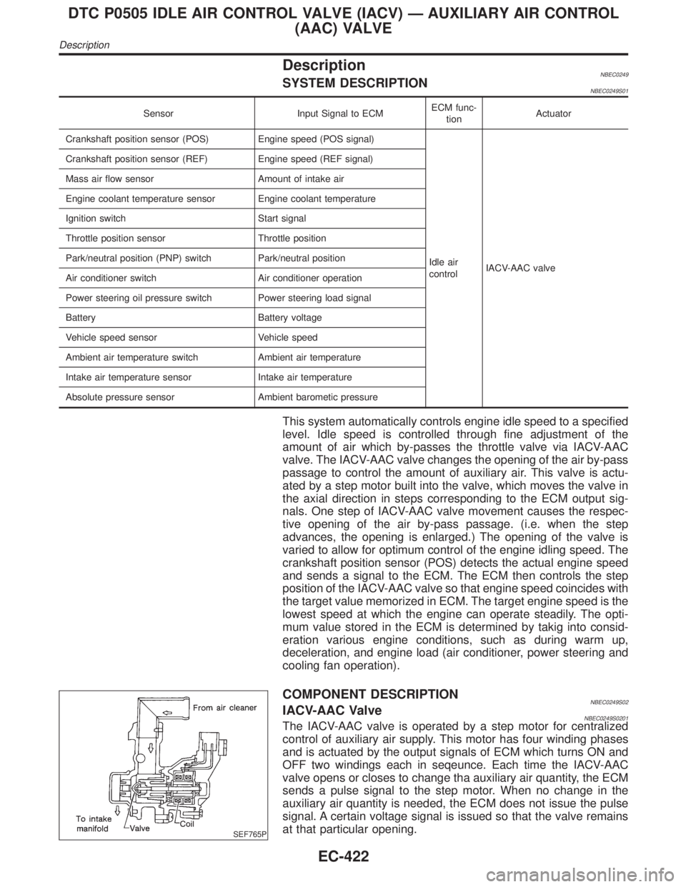
SEF765P
COMPONENT DESCRIPTIONNBEC0249S02IACV-AAC ValveNBEC0249S0201The IACV-AAC valve is operated by a step motor for centralized
control of auxiliary air supply. This motor has four winding phases
and is actuated by the output signals of ECM which turns ON and
OFF two windings each in seqeunce. Each time the IACV-AAC
valve opens or closes to change tha auxiliary air quantity, the ECM
sends a pulse signal to the step motor. When no change in the
auxiliary air quantity is needed, the ECM does not issue the pulse
signal. A certain voltage signal is issued so that the valve remains
at that particular opening.
DTC P0505 IDLE AIR CONTROL VALVE (IACV) Ð AUXILIARY AIR CONTROL
(AAC) VALVE
Description
EC-422
Page 981 of 2395

DescriptionNBEC0691SYSTEM DESCRIPTIONNBEC0691S01
Sensor Input signal to ECM function ECM Actuator
Crankshaft positon sensor (POS) Engine speed (POS)
Intake valve
timing con-
trolIntake valve timing control sole-
noid valve Crankshaft position sensor (REF) Engine speed (REF)
Camshaft position sensor Engine speed
Engine coolant temperature sensor Engine coolant temperature
Vehicle speed sensor Vehicle speed
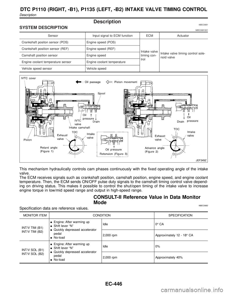
JEF349Z
This mechanism hydraulically controls cam phases continuously with the fixed operating angle of the intake
valve.
The ECM receives signals such as crankshaft position, camshaft position, engine speed, and engine coolant
temperature. Then, the ECM sends ON/OFF pulse duty signals to the camshaft timing control valve depend-
ing on driving status. This makes it possible to control the shut/open timing of the intake valve to increase
engine torque in low/mid speed range and output in high-speed range.
CONSULT-II Reference Value in Data Monitor
Mode
NBEC0692Specification data are reference values.
MONITOR ITEM CONDITION SPECIFICATION
INT/V TIM (B1)
INT/V TIM (B2)IEngine: After warming up
IShift lever ªNº
IQuickly depressed accelerator
pedal
INo-loadIdle 0É CA
2,000 rpm Approximately 12 - 18É CA
INT/V SOL (B1)
INT/V SOL (B2)IEngine: After warming up
IShift lever ªNº
IQuickly depressed accelerator
pedal
INo-loadIdle 0%
2,000 rpm Approximately 40%
DTC P1110 (RIGHT, -B1), P1135 (LEFT, -B2) INTAKE VALVE TIMING CONTROL
Description
EC-446
Page 983 of 2395
![INFINITI QX4 2001 Factory Service Manual TERMI-
NAL
NO.WIRE
COLORITEM CONDITION DATA (DC Voltage)
89 ORIntake valve timing
control position sen-
sors (LH)[Engine is running]
IWarm-up condition
IIdle speedApproximately 0.5V
SEF351Z
[Engine is INFINITI QX4 2001 Factory Service Manual TERMI-
NAL
NO.WIRE
COLORITEM CONDITION DATA (DC Voltage)
89 ORIntake valve timing
control position sen-
sors (LH)[Engine is running]
IWarm-up condition
IIdle speedApproximately 0.5V
SEF351Z
[Engine is](/manual-img/42/57027/w960_57027-982.png)
TERMI-
NAL
NO.WIRE
COLORITEM CONDITION DATA (DC Voltage)
89 ORIntake valve timing
control position sen-
sors (LH)[Engine is running]
IWarm-up condition
IIdle speedApproximately 0.5V
SEF351Z
[Engine is running]
IWarm-up condition
IEngine speed is 2,000 rpm.Approximately 0.5V
SEF352Z
On Board Diagnosis LogicNBEC0694Malfunction is detected when:
(Malfunction A)
The alignment of the intake valve timing control has been misreg-
istered.
(Malfunction B)
There is a gap between angle of target and phase-control angle
degree.
FAIL-SAFE MODENBEC0694S01When malfunction A or B is detected, the ECM enters fail-safe
mode and the MIL lights up.
Detected items Engine operating condition in fail-safe mode
Intake valve timing control The signal is not energized to the solenoid valve and the valve control does not function.
Possible CauseNBEC0695MALFUNCTION A OR BNBEC0695S01IHarness or connectors
(Intake valve timing control position sensor circuit is open or
shorted.) Refer to EC-482.
ICrankshaft position sensor (REF)
ICrankshaft position sensor (POS)
ICamshaft position sensor (PHASE)
DTC P1110 (RIGHT, -B1), P1135 (LEFT, -B2) INTAKE VALVE TIMING CONTROL
ECM Terminals and Reference Value (Cont'd)
EC-448
Page 993 of 2395

DescriptionNBEC0523If DTC P1130 is displayed with P1165, first perform trouble diag-
nosis for DTC P1165, EC-493.
SYSTEM DESCRIPTIONNBEC0523S01
Sensor Input Signal to ECMECM func-
tionActuator
Throttle position sensor Throttle position
Swirl control
valve con-
trolSwirl control valve control sole-
noid valve
"Vacuum signal
Swirl control valve actuator
"
Swirl control valve Ignition switch Start signal
Crankshaft position sensor (POS) Engine speed (POS signal)
Crankshaft position sensor (REF) Engine speed (REF signal)
Mass air flow sensor Amount of intake air
Engine coolant temperature sensor Engine coolant temperature
This system has a swirl control valve in the intake passage of each
cylinder.
While idling and during low engine speed operation, the swirl con-
trol valve closes. Thus the velocity of the air in the intake passage
increases, promoting the vaporization of the fuel and producing a
swirl in the combustion chamber.
Because of this operation, this system tends to increase the burn-
ing speed of the gas mixture, improve fuel consumption, and
increase the stability in running conditions.
Also, except when idling and during low engine speed operation,
this system opens the swirl control valve. In this condition, this
system tends to increase power by improving intake efficiency via
reduction of intake flow resistance, intake flow.
The solenoid valve controls swirl control valve's shut/open condi-
tion. This solenoid valve is operated by the ECM.
Throttle position
sensor (Idle posi-
tion)Engine speedSwirl control valve
control solenoid
valveSwirl control valve
ON Below 3,200 rpm ON Closed
OFFLess than 3,200
rpmON Closed
More than 3,600
rpmOFF Open
When engine coolant temperature is below 10ÉC (50ÉF) and above 55ÉC (131ÉF),
swirl control valve is kept open regardless of above condition.
SEF446Z
DTC P1130 SWIRL CONTROL VALVE CONTROL SOLENOID VALVE
Description
EC-458
Page 995 of 2395

Possible CauseNBEC0527MALFUNCTION ANBEC0527S01IHarness or connectors
(The swirl control valve control solenoid valve circuit is open or
shorted.)
ISwirl control valve control solenoid valve
MALFUNCTION BNBEC0527S02IHarness or connector
(The swirl control valve control solenoid valve circuit is open.)
ISwirl control valve control solenoid valve
IIntake system
(Intake air leaks)
IHoses and tubes between intake manifold, vacuum tank and
swirl control valve actuator
ISwirl control valve actuator
ISwirl control valve control vacuum check switch
IMass air flow sensor
ICrankshaft position sensor (REF)
IThrottle position sensor
MALFUNCTION CNBEC0527S03IHarness or connector
(The swirl control valve control solenoid valve circuit is
shorted.)
ISwirl control valve control vacuum check switch
ICrankshaft position sensor (REF)
IThrottle position sensor
IHoses and tubes between air cleaner and swirl control valve
vacuum check switch
ISwirl control valve control solenoid valve
DTC Confirmation ProcedureNBEC0528Perform ªProcedure for malfunction Aº first. If the 1st trip DTC
cannot be confirmed, perform ªProcedure for malfunction Bº.
If the 1st trip DTC is not confirmed on ªProcedure for malfunc-
tion Bº, perform ªProcedure for malfunction Cº.
NOTE:
If ªDTC Confirmation Procedureº has been previously conducted,
always turn ignition switch ªOFFº and wait at least 10 seconds
before conducting the next test.
SEF058Y
PROCEDURE FOR MALFUNCTION ANBEC0528S01With CONSULT-IINBEC0528S01011) Turn ignition switch ªONº.
2) Select ªDATA MONITORº mode with CONSULT-II.
3) Wait at least 5 seconds.
If 1st trip DTC is detected, go to ªDiagnostic Procedureº,
EC-463.
With GSTNBEC0528S0102Follow the procedure ªWith CONSULT-IIº above.
DTC P1130 SWIRL CONTROL VALVE CONTROL SOLENOID VALVE
Possible Cause
EC-460
Page 1009 of 2395
14 CHECK CRANKSHAFT POSITION SENSOR (REF)-I
1. Turn ignition switch ªOFFº.
2. Loosen the fixing bolts and remove the CKPS (REF).
3. Visually check the CKPS (REF) for chipping.
SEF585P
OK or NG
OK©GO TO 15.
NG©Replace crankshaft position sensor (REF).
15 CHECK CRANKSHAFT POSITION SENSOR (REF)-II
Check resistance between CKPS (REF) terminals 1 and 2.
SEF350X
OK or NG
OK©GO TO 16.
NG©Replace crankshaft position sensor (REF).
16 CHECK INTERMITTENT INCIDENT
Perform ªTROUBLE DIAGNOSIS FOR INTERMITTENT INCIDENTº, EC-140.
©INSPECTION END
PROCEDURE CNBEC0530S03
1 INSPECTION START
Do you have CONSULT-II?
YesorNo
Ye s©GO TO 2.
No©GO TO 3.
DTC P1130 SWIRL CONTROL VALVE CONTROL SOLENOID VALVE
Diagnostic Procedure (Cont'd)
EC-474
Page 1013 of 2395
8 CHECK SWIRL CONTROL VALVE CONTROL VACUUM CHECK SWITCH
1. Turn ignition switch ªOFFº.
2. Disconnect vacuum hose connected to swirl control valve control vacuum check switch.
3. Attach vacuum pump to swirl control valve control vacuum check switch.
4. Turn ignition switch ªONº.
5. Check voltage between ECM terminal 55 and ground under the following conditions.
SEF709X
OK or NG
OK©GO TO 9.
NG©Replace swirl control valve control vacuum check switch.
9 CHECK CRANKSHAFT POSITION SENSOR (REF)-I
1. Turn ignition switch ªOFFº.
2. Loosen the fixing bolts and remove the CKPS (REF).
3. Visually check the CKPS (REF) for chipping.
SEF585P
OK or NG
OK©GO TO 10.
NG©Replace crankshaft position sensor (REF).
DTC P1130 SWIRL CONTROL VALVE CONTROL SOLENOID VALVE
Diagnostic Procedure (Cont'd)
EC-478
Page 1014 of 2395
10 CHECK CRANKSHAFT POSITION SENSOR (REF)-II
Check resistance between CKPS (REF) terminals 1 and 2.
SEF350X
OK or NG
OK (With CONSULT-II)©GO TO 11.
OK (Without CONSULT-
II)©GO TO 12.
NG©Replace crankshaft position sensor (REF).
GI
MA
EM
LC
FE
AT
TF
PD
AX
SU
BR
ST
RS
BT
HA
SC
EL
IDX
DTC P1130 SWIRL CONTROL VALVE CONTROL SOLENOID VALVE
Diagnostic Procedure (Cont'd)
EC-479