Page 1834 of 2395
Circuit Diagram (With Navigation System)NBHA0113
MHA978A
GI
MA
EM
LC
EC
FE
AT
TF
PD
AX
SU
BR
ST
RS
BT
SC
EL
IDX
TROUBLE DIAGNOSES
Circuit Diagram (With Navigation System)
HA-35
Page 1835 of 2395
Wiring Diagram Ð A/C, A Ð (With Navigation
System)
NBHA0114
MHA979A
TROUBLE DIAGNOSES
Wiring Diagram Ð A/C, A Ð (With Navigation System)
HA-36
Page 1836 of 2395
MHA980A
GI
MA
EM
LC
EC
FE
AT
TF
PD
AX
SU
BR
ST
RS
BT
SC
EL
IDX
TROUBLE DIAGNOSES
Wiring Diagram Ð A/C, A Ð (With Navigation System) (Cont'd)
HA-37
Page 1837 of 2395
MHA981A
TROUBLE DIAGNOSES
Wiring Diagram Ð A/C, A Ð (With Navigation System) (Cont'd)
HA-38
Page 1838 of 2395
MHA982A
GI
MA
EM
LC
EC
FE
AT
TF
PD
AX
SU
BR
ST
RS
BT
SC
EL
IDX
TROUBLE DIAGNOSES
Wiring Diagram Ð A/C, A Ð (With Navigation System) (Cont'd)
HA-39
Page 1900 of 2395
6 CHECK FAN FEED BACK CIRCUIT
Reconnect auto amp. (LCU) harness connector.
Do approx. 12 volts exist between auto amp. (LCU) harness terminal No. 33 and body ground?
RHA825H
YesorNo
Ye s©GO TO 7.
No©Check power supply circuit and 15A fuses (Nos. 1 and 2, located in the fuse block).
Refer to EL-14, ªWiring Diagram Ð POWER к.
IIf OK, check for open circuit in wiring harness.
Repair or replace as necessary.
IIf NG, replace fuse and check wiring harness for short circuit.
Repair or replace as necessary.
7 CHECK POWER SUPPLY FOR AUTO AMP.
Do approx. 12 volts exist between auto amp. harness terminal No. 34 and body ground?
RHA826H
YesorNo
Ye s©1. Replace auto amp.
2. Go to self-diagnosis step-by-step procedure (HA-45) and perform self-diagnosis STEP
4.
Confirm that blower motor operation is normal.
No©GO TO 10.
GI
MA
EM
LC
EC
FE
AT
TF
PD
AX
SU
BR
ST
RS
BT
SC
EL
IDX
TROUBLE DIAGNOSES
Blower Motor (Cont'd)
HA-101
Page 1906 of 2395

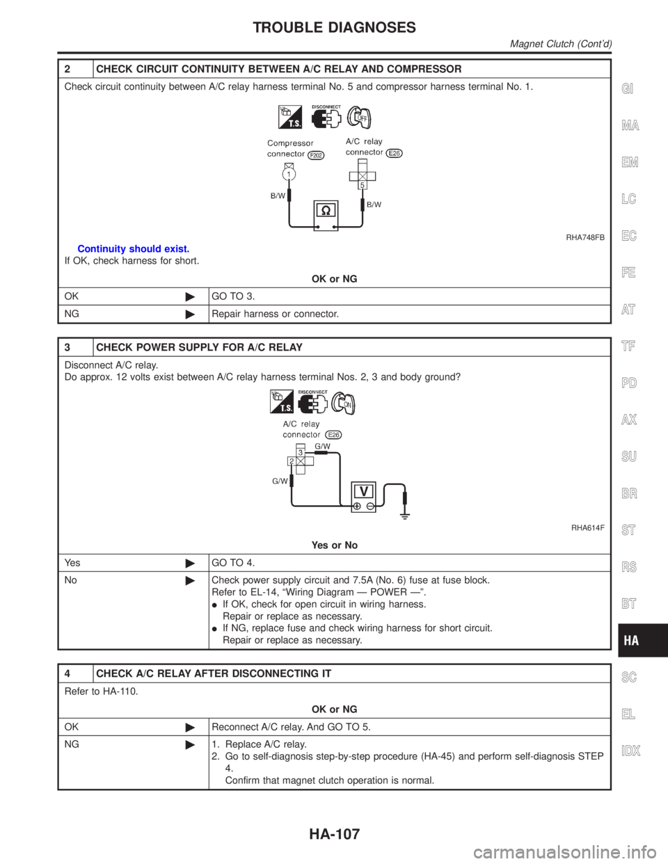
2 CHECK CIRCUIT CONTINUITY BETWEEN A/C RELAY AND COMPRESSOR
Check circuit continuity between A/C relay harness terminal No. 5 and compressor harness terminal No. 1.
RHA748FB
Continuity should exist.
If OK, check harness for short.
OK or NG
OK©GO TO 3.
NG©Repair harness or connector.
3 CHECK POWER SUPPLY FOR A/C RELAY
Disconnect A/C relay.
Do approx. 12 volts exist between A/C relay harness terminal Nos. 2, 3 and body ground?
RHA614F
YesorNo
Ye s©GO TO 4.
No©Check power supply circuit and 7.5A (No. 6) fuse at fuse block.
Refer to EL-14, ªWiring Diagram Ð POWER к.
IIf OK, check for open circuit in wiring harness.
Repair or replace as necessary.
IIf NG, replace fuse and check wiring harness for short circuit.
Repair or replace as necessary.
4 CHECK A/C RELAY AFTER DISCONNECTING IT
Refer to HA-110.
OK or NG
OK©Reconnect A/C relay. And GO TO 5.
NG©1. Replace A/C relay.
2. Go to self-diagnosis step-by-step procedure (HA-45) and perform self-diagnosis STEP
4.
Confirm that magnet clutch operation is normal.
GI
MA
EM
LC
EC
FE
AT
TF
PD
AX
SU
BR
ST
RS
BT
SC
EL
IDX
TROUBLE DIAGNOSES
Magnet Clutch (Cont'd)
HA-107
Page 1961 of 2395

A
AAC/V - Wiring diagram ...............................EC-425
ABS - Wiring diagram ....................................BR-37
ABS sensor rotor ........................................AX-6, 19
Absolute pressure sensor ............................EC-158
A/C air flow .....................................................HA-25
A/C component layout ....................................HA-19
A/C compressor clutch removal and
installation .................................................HA-150
A/C compressor precaution..............................HA-6
A/C compressor special service tool..............HA-10
A/C control operation (auto A/C) ....................HA-23
A/C diagnostic work flow (auto A/C) ..............HA-65
A/C HFC134a (R134a) system
precaution .....................................................HA-2
A/C HFC134a (R134a) system service
procedure ..................................................HA-144
A/C HFC134a (R134a) system service
tools.............................................................HA-11
A/C HFC134a system service equip-
ment precaution ............................................HA-7
A/C lubricant (R134a)...................................HA-146
A/C operational check ....................................HA-66
A/C performance chart .................................HA-116
A/C performance test diagnoses ..................HA-114
A/C relay .......................................................HA-110
A/C self-diagnoses (auto A/C)........................HA-44
A/C service data specification ......................HA-160
A/C system description (auto A/C) .................HA-23
A/C trouble diagnoses (auto A/C) ..................HA-27
A/C, A - Wiring diagram ...........................HA-31, 36
Accelerator control system ...............................FE-3
Accelerator wire adjustment .............................FE-3
Actuator lever (Transfer) ...............................TF-120
Air bag ............................................................RS-10
Air bag disposal..............................................RS-22
Air bag precautions ...........................................GI-3
Air bleeding for brake system ..........................BR-8
Air cleaner filter replacement .........................MA-17
Air conditioner cut control ..............................EC-31
Air flow meter - See Mass air flow
sensor .......................................................EC-150
Air mix door control linkage adjustment.........HA-85
Air mix. door motor ................................HA-82, 141
Air spoiler, rear................................................BT-35
All - mode 4WD system ..................................TF-10
Alternator ........................................................SC-28
Ambient sensor ............................................HA-129
Angular tightening application..........................EM-3
Antenna - See Power antenna .....................EL-169
Anti-lock brake system - Wiring
diagram .......................................................BR-37
AP/SEN - Wiring diagram ............................EC-160
ASCD (automatic speed control device) ......EL-221
ASCD - Wiring diagram ................................EL-225
A/T - Wiring diagram - AT - FTS ...................AT-107
A/T - Wiring diagram - AT - MAIN ...................AT-96
A/T - Wiring diagram - AT - PNP/SW............AT-101A/T - Wiring diagram - AT - VSS A/T ............AT-113
A/T control ....................................................EC-440
A/T diagnosis communication line................EC-603
A/T fluid temperature sensor .........................AT-110
A/T self-diagnoses...........................................AT-46
A/T shift lock system .....................................AT-265
A/T shift lock system - Wiring diagram .........AT-266
A/T trouble diagnoses .....................................AT-53
A/T Wiring diagram - AT - ENG SS...............AT-117
A/T Wiring diagram AT - 1ST ........................AT-123
A/T Wiring diagram AT - 2ND .......................AT-129
A/T Wiring diagram AT - 3RD .......................AT-135
A/T Wiring diagram AT - 4TH ........................AT-142
A/T Wiring diagram AT - BA/FTS ..................AT-192
A/T Wiring diagram AT - LPSV .....................AT-164
A/T Wiring diagram AT - NONDTC ...............AT-215
A/T Wiring diagram AT - OVRCSV ...............AT-187
A/T Wiring diagram AT - SSV/A ....................AT-169
A/T Wiring diagram AT - SSV/B ....................AT-173
A/T Wiring diagram AT - TCCSIG .................AT-156
A/T Wiring diagram AT - TCV .......................AT-150
A/T Wiring diagram AT - TPS........................AT-179
A/T Wiring diagram AT - VSSMTR................AT-199
AT/C - Wiring diagram ..................................EC-442
ATP switch.....................................................TF-112
ATP warning lamp .........................................TF-102
Audio .............................................................EL-160
AUDIO - Wiring diagram ...............................EL-162
Audio and A/C control removal and
installation - See Instrument panel .............BT-21
AUT/DP - Wiring diagram .............................EL-191
Auto air conditioner - Wiring diagram ......HA-31, 36
Automatic amplifier...................................HA-40, 72
Automatic drive positioner ............................EL-186
Automatic speed control system - See
ASCD ........................................................EL-221
Automatic transmission fluid
replacement ................................................MA-21
Automatic transmission number ......................GI-43
Auxiliary air control (AAC) valve ..................EC-422
Axle housing (rear) .........................................AX-19
B
Back door ........................................................BT-15
Back door opener - See Back door ................BT-15
Back door trim.................................................BT-34
Back-up lamp ..................................................EL-69
BACK/L - Wiring diagram................................EL-69
Ball joint (front) ...............................................SU-12
Base idle air volume initialiging......................EC-57
Basic inspection ...........................................EC-101
Battery ..............................................................SC-4
Battery/Starting/Charging System
Tester ................................................SC-7, 12, 21
Blower motor ..................................................HA-95
Body alignment ...............................................BT-57
Brake booster .................................................BR-19
Brake control valve (Proportioning
valve)...........................................................BR-11
ALPHABETICAL INDEX
IDX-2