2001 INFINITI QX4 diagram
[x] Cancel search: diagramPage 1643 of 2395
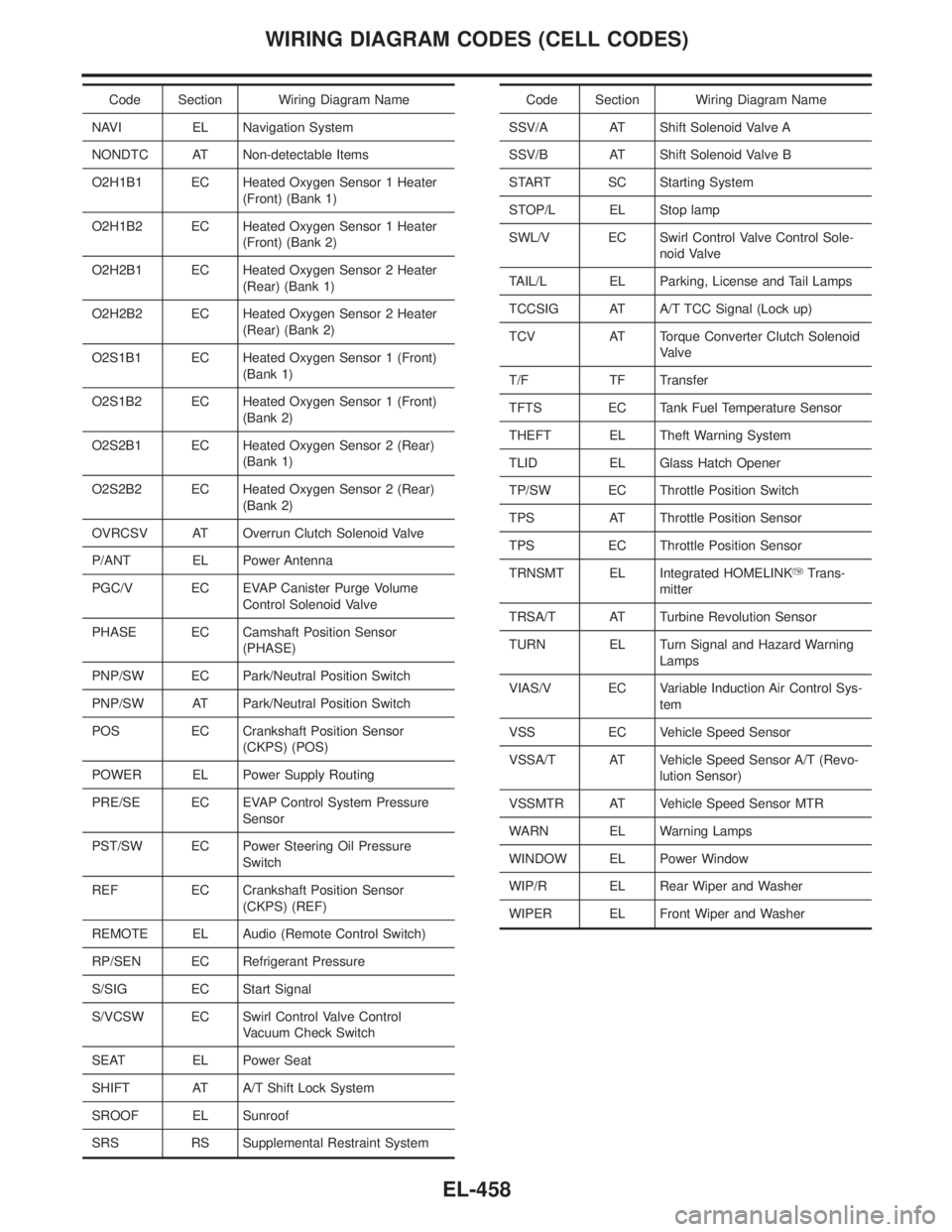
Code Section Wiring Diagram Name
NAVI EL Navigation System
NONDTC AT Non-detectable Items
O2H1B1 EC Heated Oxygen Sensor 1 Heater
(Front) (Bank 1)
O2H1B2 EC Heated Oxygen Sensor 1 Heater
(Front) (Bank 2)
O2H2B1 EC Heated Oxygen Sensor 2 Heater
(Rear) (Bank 1)
O2H2B2 EC Heated Oxygen Sensor 2 Heater
(Rear) (Bank 2)
O2S1B1 EC Heated Oxygen Sensor 1 (Front)
(Bank 1)
O2S1B2 EC Heated Oxygen Sensor 1 (Front)
(Bank 2)
O2S2B1 EC Heated Oxygen Sensor 2 (Rear)
(Bank 1)
O2S2B2 EC Heated Oxygen Sensor 2 (Rear)
(Bank 2)
OVRCSV AT Overrun Clutch Solenoid Valve
P/ANT EL Power Antenna
PGC/V EC EVAP Canister Purge Volume
Control Solenoid Valve
PHASE EC Camshaft Position Sensor
(PHASE)
PNP/SW EC Park/Neutral Position Switch
PNP/SW AT Park/Neutral Position Switch
POS EC Crankshaft Position Sensor
(CKPS) (POS)
POWER EL Power Supply Routing
PRE/SE EC EVAP Control System Pressure
Sensor
PST/SW EC Power Steering Oil Pressure
Switch
REF EC Crankshaft Position Sensor
(CKPS) (REF)
REMOTE EL Audio (Remote Control Switch)
RP/SEN EC Refrigerant Pressure
S/SIG EC Start Signal
S/VCSW EC Swirl Control Valve Control
Vacuum Check Switch
SEAT EL Power Seat
SHIFT AT A/T Shift Lock System
SROOF EL Sunroof
SRS RS Supplemental Restraint SystemCode Section Wiring Diagram Name
SSV/A AT Shift Solenoid Valve A
SSV/B AT Shift Solenoid Valve B
START SC Starting System
STOP/L EL Stop lamp
SWL/V EC Swirl Control Valve Control Sole-
noid Valve
TAIL/L EL Parking, License and Tail Lamps
TCCSIG AT A/T TCC Signal (Lock up)
TCV AT Torque Converter Clutch Solenoid
Valve
T/F TF Transfer
TFTS EC Tank Fuel Temperature Sensor
THEFT EL Theft Warning System
TLID EL Glass Hatch Opener
TP/SW EC Throttle Position Switch
TPS AT Throttle Position Sensor
TPS EC Throttle Position Sensor
TRNSMT EL Integrated HOMELINKYTrans-
mitter
TRSA/T AT Turbine Revolution Sensor
TURN EL Turn Signal and Hazard Warning
Lamps
VIAS/V EC Variable Induction Air Control Sys-
tem
VSS EC Vehicle Speed Sensor
VSSA/T AT Vehicle Speed Sensor A/T (Revo-
lution Sensor)
VSSMTR AT Vehicle Speed Sensor MTR
WARN EL Warning Lamps
WINDOW EL Power Window
WIP/R EL Rear Wiper and Washer
WIPER EL Front Wiper and Washer
WIRING DIAGRAM CODES (CELL CODES)
EL-458
Page 1746 of 2395
GENERAL INFORMATION
SECTION
GI
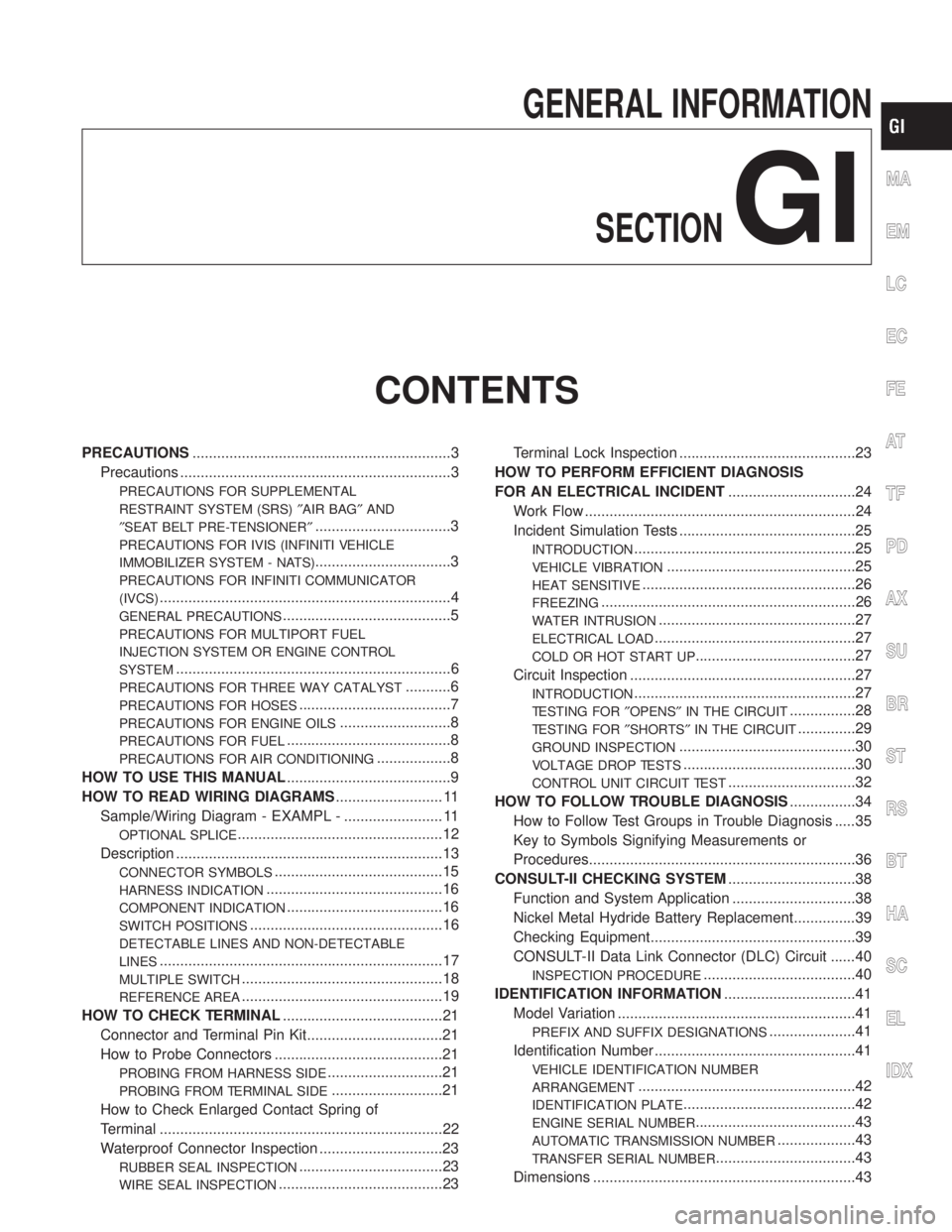
CONTENTS
PRECAUTIONS...............................................................3
Precautions ..................................................................3
PRECAUTIONS FOR SUPPLEMENTAL
RESTRAINT SYSTEM (SRS)²AIR BAG²AND
²SEAT BELT PRE-TENSIONER²
.................................3
PRECAUTIONS FOR IVIS (INFINITI VEHICLE
IMMOBILIZER SYSTEM - NATS)
.................................3
PRECAUTIONS FOR INFINITI COMMUNICATOR
(IVCS)
.......................................................................4
GENERAL PRECAUTIONS.........................................5
PRECAUTIONS FOR MULTIPORT FUEL
INJECTION SYSTEM OR ENGINE CONTROL
SYSTEM
...................................................................6
PRECAUTIONS FOR THREE WAY CATALYST...........6
PRECAUTIONS FOR HOSES.....................................7
PRECAUTIONS FOR ENGINE OILS...........................8
PRECAUTIONS FOR FUEL........................................8
PRECAUTIONS FOR AIR CONDITIONING..................8
HOW TO USE THIS MANUAL........................................9
HOW TO READ WIRING DIAGRAMS.......................... 11
Sample/Wiring Diagram - EXAMPL - ........................ 11
OPTIONAL SPLICE..................................................12
Description .................................................................13
CONNECTOR SYMBOLS.........................................15
HARNESS INDICATION...........................................16
COMPONENT INDICATION......................................16
SWITCH POSITIONS...............................................16
DETECTABLE LINES AND NON-DETECTABLE
LINES
.....................................................................17
MULTIPLE SWITCH.................................................18
REFERENCE AREA.................................................19
HOW TO CHECK TERMINAL.......................................21
Connector and Terminal Pin Kit.................................21
How to Probe Connectors .........................................21
PROBING FROM HARNESS SIDE............................21
PROBING FROM TERMINAL SIDE...........................21
How to Check Enlarged Contact Spring of
Terminal .....................................................................22
Waterproof Connector Inspection ..............................23
RUBBER SEAL INSPECTION...................................23
WIRE SEAL INSPECTION........................................23Terminal Lock Inspection ...........................................23
HOW TO PERFORM EFFICIENT DIAGNOSIS
FOR AN ELECTRICAL INCIDENT...............................24
Work Flow ..................................................................24
Incident Simulation Tests ...........................................25
INTRODUCTION......................................................25
VEHICLE VIBRATION..............................................25
HEAT SENSITIVE....................................................26
FREEZING..............................................................26
WATER INTRUSION................................................27
ELECTRICAL LOAD.................................................27
COLD OR HOT START UP.......................................27
Circuit Inspection .......................................................27
INTRODUCTION......................................................27
TESTING FOR²OPENS²IN THE CIRCUIT................28
TESTING FOR²SHORTS²IN THE CIRCUIT..............29
GROUND INSPECTION...........................................30
VOLTAGE DROP TESTS..........................................30
CONTROL UNIT CIRCUIT TEST...............................32
HOW TO FOLLOW TROUBLE DIAGNOSIS................34
How to Follow Test Groups in Trouble Diagnosis .....35
Key to Symbols Signifying Measurements or
Procedures.................................................................36
CONSULT-II CHECKING SYSTEM...............................38
Function and System Application ..............................38
Nickel Metal Hydride Battery Replacement...............39
Checking Equipment..................................................39
CONSULT-II Data Link Connector (DLC) Circuit ......40
INSPECTION PROCEDURE.....................................40
IDENTIFICATION INFORMATION................................41
Model Variation ..........................................................41
PREFIX AND SUFFIX DESIGNATIONS.....................41
Identification Number .................................................41
VEHICLE IDENTIFICATION NUMBER
ARRANGEMENT
.....................................................42
IDENTIFICATION PLATE..........................................42
ENGINE SERIAL NUMBER.......................................43
AUTOMATIC TRANSMISSION NUMBER...................43
TRANSFER SERIAL NUMBER..................................43
Dimensions ................................................................43
MA
EM
LC
EC
FE
AT
TF
PD
AX
SU
BR
ST
RS
BT
HA
SC
EL
IDX
Page 1756 of 2395

NBGI0003
Sample/Wiring Diagram Ð EXAMPL ÐNBGI0003S01IFor Description, refer to GI-13.
SGI134A
MA
EM
LC
EC
FE
AT
TF
PD
AX
SU
BR
ST
RS
BT
HA
SC
EL
IDX
HOW TO READ WIRING DIAGRAMS
Sample/Wiring Diagram Ð EXAMPL Ð
GI-11
Page 1757 of 2395
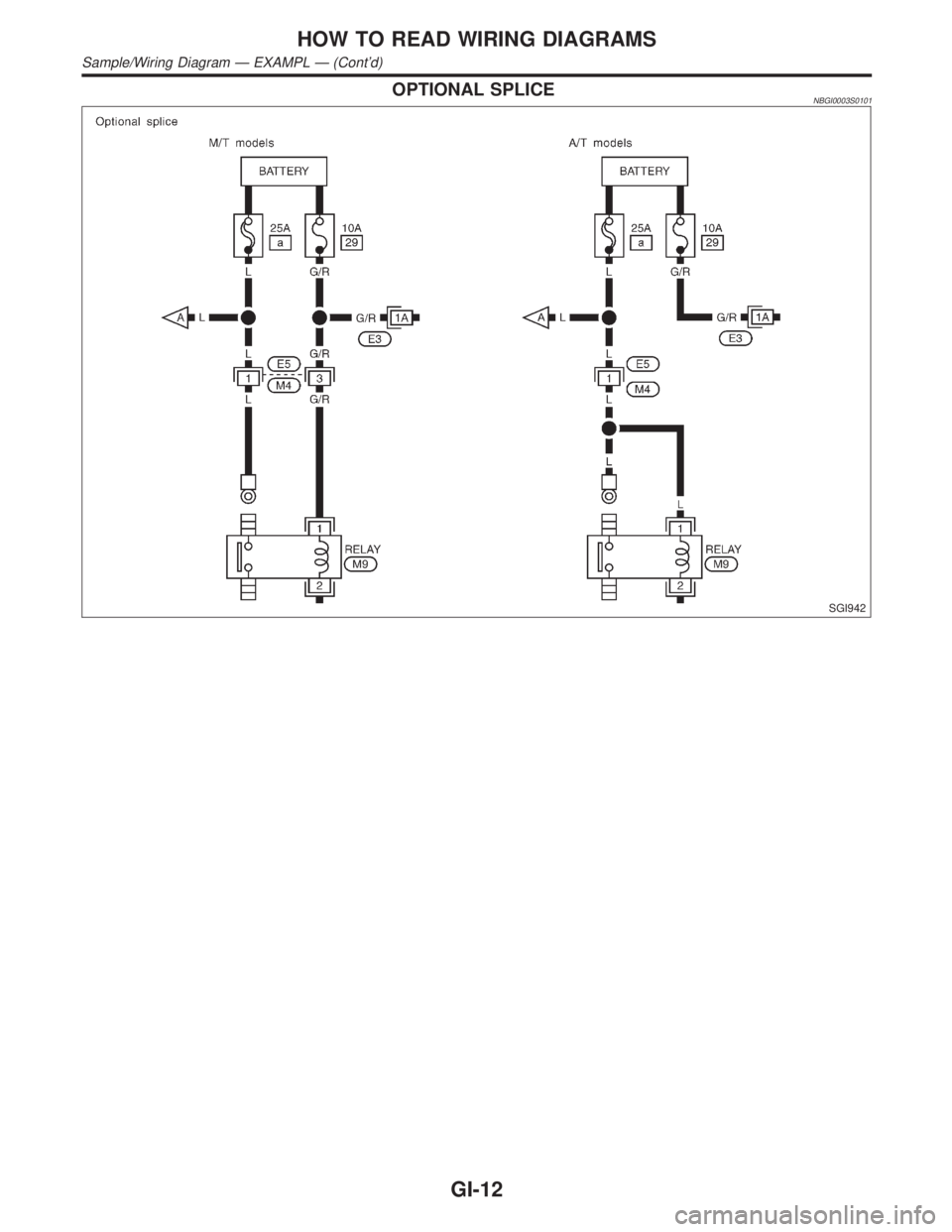
OPTIONAL SPLICENBGI0003S0101
SGI942
HOW TO READ WIRING DIAGRAMS
Sample/Wiring Diagram Ð EXAMPL Ð (Cont'd)
GI-12
Page 1758 of 2395
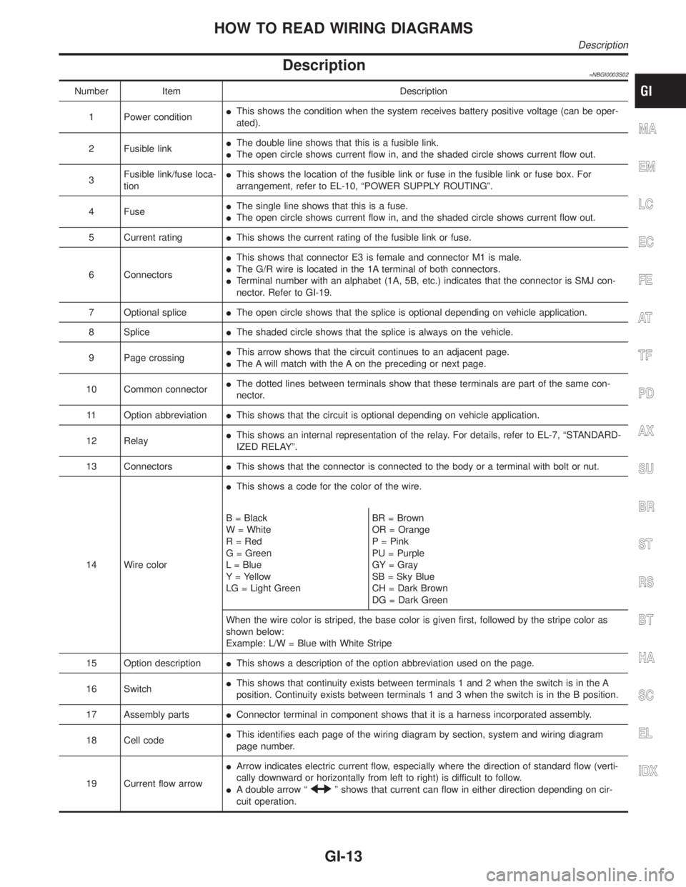
Description=NBGI0003S02
Number Item Description
1 Power conditionIThis shows the condition when the system receives battery positive voltage (can be oper-
ated).
2 Fusible linkIThe double line shows that this is a fusible link.
IThe open circle shows current flow in, and the shaded circle shows current flow out.
3Fusible link/fuse loca-
tionIThis shows the location of the fusible link or fuse in the fusible link or fuse box. For
arrangement, refer to EL-10, ªPOWER SUPPLY ROUTINGº.
4 FuseIThe single line shows that this is a fuse.
IThe open circle shows current flow in, and the shaded circle shows current flow out.
5 Current ratingIThis shows the current rating of the fusible link or fuse.
6 ConnectorsIThis shows that connector E3 is female and connector M1 is male.
IThe G/R wire is located in the 1A terminal of both connectors.
ITerminal number with an alphabet (1A, 5B, etc.) indicates that the connector is SMJ con-
nector. Refer to GI-19.
7 Optional spliceIThe open circle shows that the splice is optional depending on vehicle application.
8 SpliceIThe shaded circle shows that the splice is always on the vehicle.
9 Page crossingIThis arrow shows that the circuit continues to an adjacent page.
IThe A will match with the A on the preceding or next page.
10 Common connectorIThe dotted lines between terminals show that these terminals are part of the same con-
nector.
11 Option abbreviationIThis shows that the circuit is optional depending on vehicle application.
12 RelayIThis shows an internal representation of the relay. For details, refer to EL-7, ªSTANDARD-
IZED RELAYº.
13 ConnectorsIThis shows that the connector is connected to the body or a terminal with bolt or nut.
14 Wire colorIThis shows a code for the color of the wire.
B = Black
W = White
R = Red
G = Green
L = Blue
Y = Yellow
LG = Light GreenBR = Brown
OR = Orange
P = Pink
PU = Purple
GY = Gray
SB = Sky Blue
CH = Dark Brown
DG = Dark Green
When the wire color is striped, the base color is given first, followed by the stripe color as
shown below:
Example: L/W = Blue with White Stripe
15 Option descriptionIThis shows a description of the option abbreviation used on the page.
16 SwitchIThis shows that continuity exists between terminals 1 and 2 when the switch is in the A
position. Continuity exists between terminals 1 and 3 when the switch is in the B position.
17 Assembly partsIConnector terminal in component shows that it is a harness incorporated assembly.
18 Cell codeIThis identifies each page of the wiring diagram by section, system and wiring diagram
page number.
19 Current flow arrowIArrow indicates electric current flow, especially where the direction of standard flow (verti-
cally downward or horizontally from left to right) is difficult to follow.
IA double arrow ª
º shows that current can flow in either direction depending on cir-
cuit operation.
MA
EM
LC
EC
FE
AT
TF
PD
AX
SU
BR
ST
RS
BT
HA
SC
EL
IDX
HOW TO READ WIRING DIAGRAMS
Description
GI-13
Page 1759 of 2395
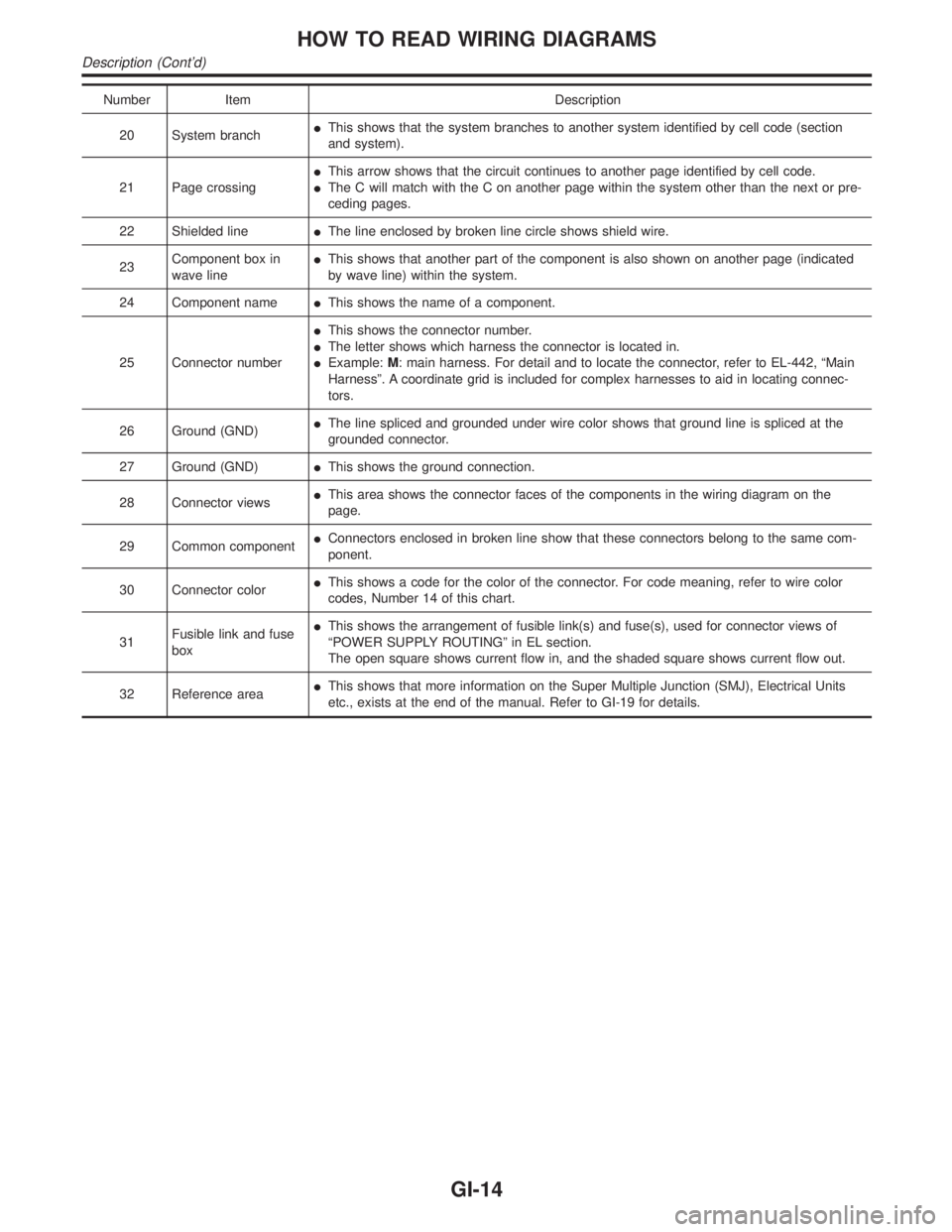
Number Item Description
20 System branchIThis shows that the system branches to another system identified by cell code (section
and system).
21 Page crossingIThis arrow shows that the circuit continues to another page identified by cell code.
IThe C will match with the C on another page within the system other than the next or pre-
ceding pages.
22 Shielded lineIThe line enclosed by broken line circle shows shield wire.
23Component box in
wave lineIThis shows that another part of the component is also shown on another page (indicated
by wave line) within the system.
24 Component nameIThis shows the name of a component.
25 Connector numberIThis shows the connector number.
IThe letter shows which harness the connector is located in.
IExample:M: main harness. For detail and to locate the connector, refer to EL-442, ªMain
Harnessº. A coordinate grid is included for complex harnesses to aid in locating connec-
tors.
26 Ground (GND)IThe line spliced and grounded under wire color shows that ground line is spliced at the
grounded connector.
27 Ground (GND)IThis shows the ground connection.
28 Connector viewsIThis area shows the connector faces of the components in the wiring diagram on the
page.
29 Common componentIConnectors enclosed in broken line show that these connectors belong to the same com-
ponent.
30 Connector colorIThis shows a code for the color of the connector. For code meaning, refer to wire color
codes, Number 14 of this chart.
31Fusible link and fuse
boxIThis shows the arrangement of fusible link(s) and fuse(s), used for connector views of
ªPOWER SUPPLY ROUTINGº in EL section.
The open square shows current flow in, and the shaded square shows current flow out.
32 Reference areaIThis shows that more information on the Super Multiple Junction (SMJ), Electrical Units
etc., exists at the end of the manual. Refer to GI-19 for details.
HOW TO READ WIRING DIAGRAMS
Description (Cont'd)
GI-14
Page 1760 of 2395
SGI364
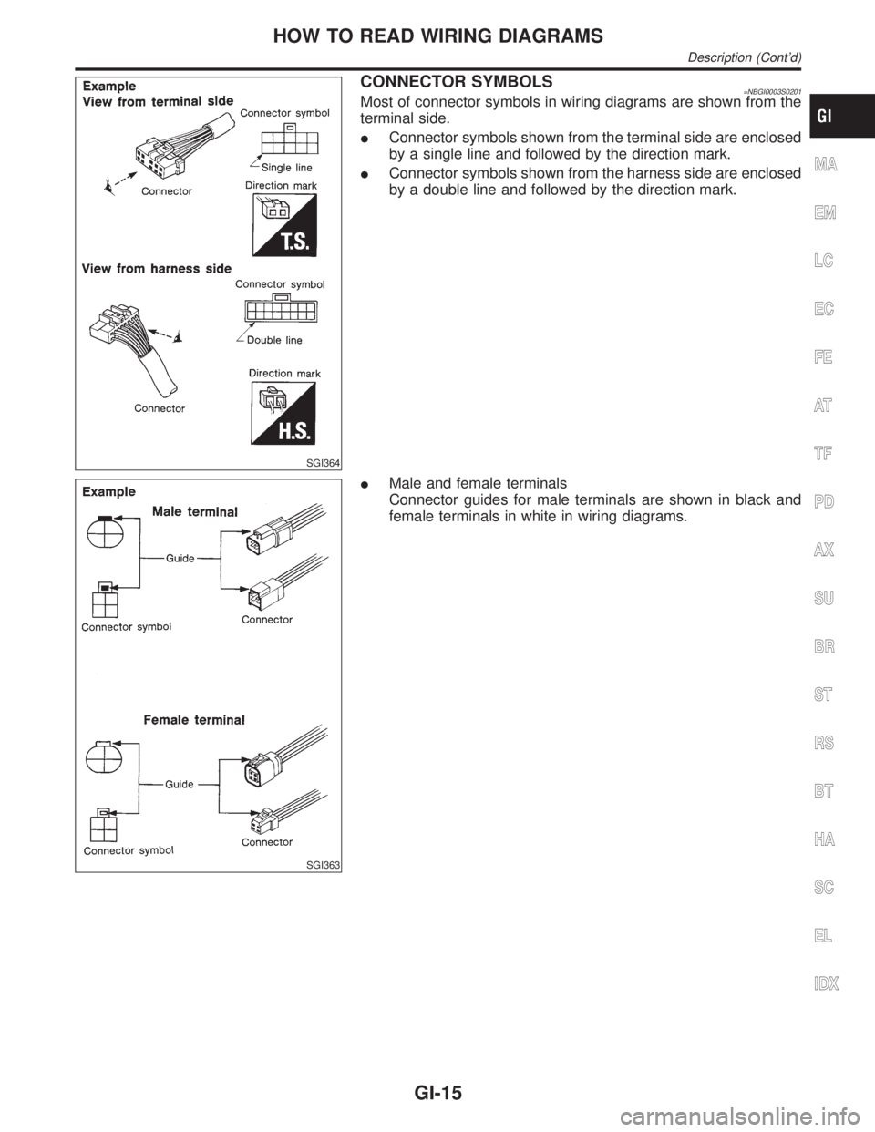
CONNECTOR SYMBOLS=NBGI0003S0201Most of connector symbols in wiring diagrams are shown from the
terminal side.
IConnector symbols shown from the terminal side are enclosed
by a single line and followed by the direction mark.
IConnector symbols shown from the harness side are enclosed
by a double line and followed by the direction mark.
SGI363
IMale and female terminals
Connector guides for male terminals are shown in black and
female terminals in white in wiring diagrams.
MA
EM
LC
EC
FE
AT
TF
PD
AX
SU
BR
ST
RS
BT
HA
SC
EL
IDX
HOW TO READ WIRING DIAGRAMS
Description (Cont'd)
GI-15
Page 1761 of 2395
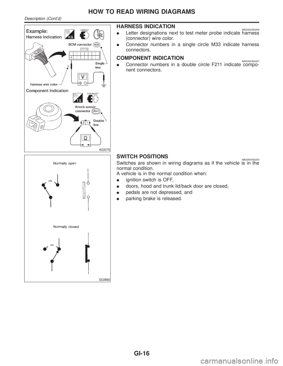
AGI070
HARNESS INDICATIONNBGI0003S0206ILetter designations next to test meter probe indicate harness
(connector) wire color.
IConnector numbers in a single circle M33 indicate harness
connectors.
COMPONENT INDICATIONNBGI0003S0207IConnector numbers in a double circle F211 indicate compo-
nent connectors.
SGI860
SWITCH POSITIONSNBGI0003S0202Switches are shown in wiring diagrams as if the vehicle is in the
normal condition.
A vehicle is in the normal condition when:
Iignition switch is OFF,
Idoors, hood and trunk lid/back door are closed,
Ipedals are not depressed, and
Iparking brake is released.
HOW TO READ WIRING DIAGRAMS
Description (Cont'd)
GI-16