2001 INFINITI QX4 fuse diagram
[x] Cancel search: fuse diagramPage 1759 of 2395
Number Item Description
20 System branchIThis shows that the system branches to another system identified by cell code (section
and system).
21 Page crossingIThis arrow shows that the circuit continues to another page identified by cell code.
IThe C will match with the C on another page within the system other than the next or pre-
ceding pages.
22 Shielded lineIThe line enclosed by broken line circle shows shield wire.
23Component box in
wave lineIThis shows that another part of the component is also shown on another page (indicated
by wave line) within the system.
24 Component nameIThis shows the name of a component.
25 Connector numberIThis shows the connector number.
IThe letter shows which harness the connector is located in.
IExample:M: main harness. For detail and to locate the connector, refer to EL-442, ªMain
Harnessº. A coordinate grid is included for complex harnesses to aid in locating connec-
tors.
26 Ground (GND)IThe line spliced and grounded under wire color shows that ground line is spliced at the
grounded connector.
27 Ground (GND)IThis shows the ground connection.
28 Connector viewsIThis area shows the connector faces of the components in the wiring diagram on the
page.
29 Common componentIConnectors enclosed in broken line show that these connectors belong to the same com-
ponent.
30 Connector colorIThis shows a code for the color of the connector. For code meaning, refer to wire color
codes, Number 14 of this chart.
31Fusible link and fuse
boxIThis shows the arrangement of fusible link(s) and fuse(s), used for connector views of
ªPOWER SUPPLY ROUTINGº in EL section.
The open square shows current flow in, and the shaded square shows current flow out.
32 Reference areaIThis shows that more information on the Super Multiple Junction (SMJ), Electrical Units
etc., exists at the end of the manual. Refer to GI-19 for details.
HOW TO READ WIRING DIAGRAMS
Description (Cont'd)
GI-14
Page 1765 of 2395
manual.
Fuse block Ð Junction box (J/B)
Fuse block Ð Junction box (J/B) connector number is shown in the
Reference Area of the wiring diagram. For connector terminal and
fuse arrangement, refer to the ªFUSE BLOCK Ð Junction Box
(J/B)º electrical reference page at the end of the manual.
Fuse and fusible link box
For fuse arrangement in the fuse and fusible link box, refer to the
ªFUSE AND FUSIBLE LINK BOXº electrical reference page at the
end of the manual.
Electrical units
Electrical unit connector symbols are shown in the Connector Area
of the wiring diagram.
However, when there is not enough space to show the connector
terminal arrangement in the Connector Area of the wiring diagram,
the electrical unit connector number is shown in the Reference
Area of the wiring diagram. For electrical unit connector terminal
arrangement, refer to the ªELECTRICAL UNITSº electrical refer-
ence page at the end of the manual. Most of the electrical unit
connectors on this page are shown from the harness side of the
connector.
Joint connector
Joint connector symbols are shown in the connector area of the
wiring diagram. For connector internal wiring layout and joint con-
nector terminal arrangement, refer to the ªJOINT CONNECTOR
(J/C)º electrical reference page at the end of the manual.
HOW TO READ WIRING DIAGRAMS
Description (Cont'd)
GI-20
Page 1900 of 2395
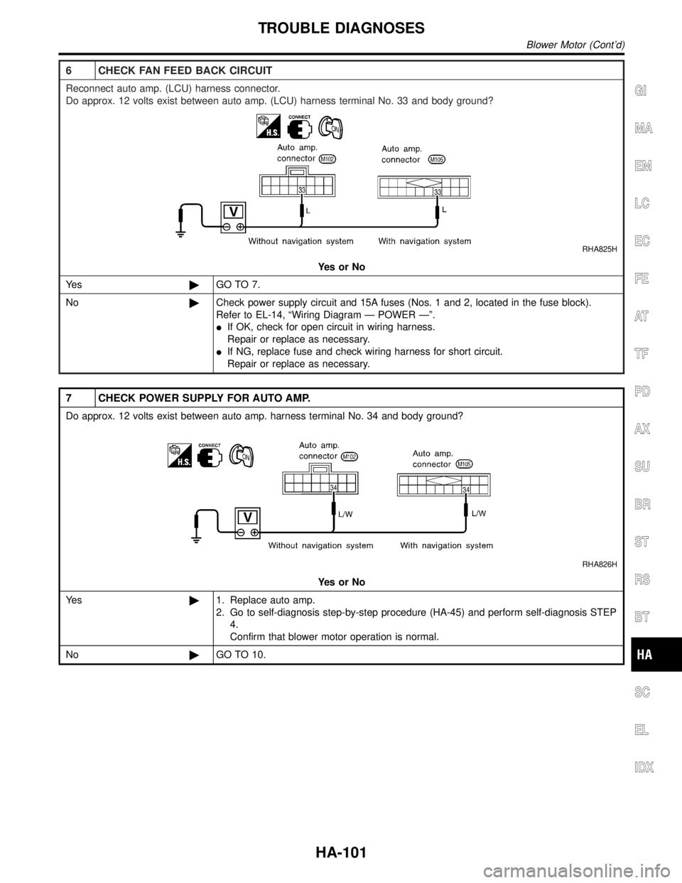
6 CHECK FAN FEED BACK CIRCUIT
Reconnect auto amp. (LCU) harness connector.
Do approx. 12 volts exist between auto amp. (LCU) harness terminal No. 33 and body ground?
RHA825H
YesorNo
Ye s©GO TO 7.
No©Check power supply circuit and 15A fuses (Nos. 1 and 2, located in the fuse block).
Refer to EL-14, ªWiring Diagram Ð POWER к.
IIf OK, check for open circuit in wiring harness.
Repair or replace as necessary.
IIf NG, replace fuse and check wiring harness for short circuit.
Repair or replace as necessary.
7 CHECK POWER SUPPLY FOR AUTO AMP.
Do approx. 12 volts exist between auto amp. harness terminal No. 34 and body ground?
RHA826H
YesorNo
Ye s©1. Replace auto amp.
2. Go to self-diagnosis step-by-step procedure (HA-45) and perform self-diagnosis STEP
4.
Confirm that blower motor operation is normal.
No©GO TO 10.
GI
MA
EM
LC
EC
FE
AT
TF
PD
AX
SU
BR
ST
RS
BT
SC
EL
IDX
TROUBLE DIAGNOSES
Blower Motor (Cont'd)
HA-101
Page 1906 of 2395
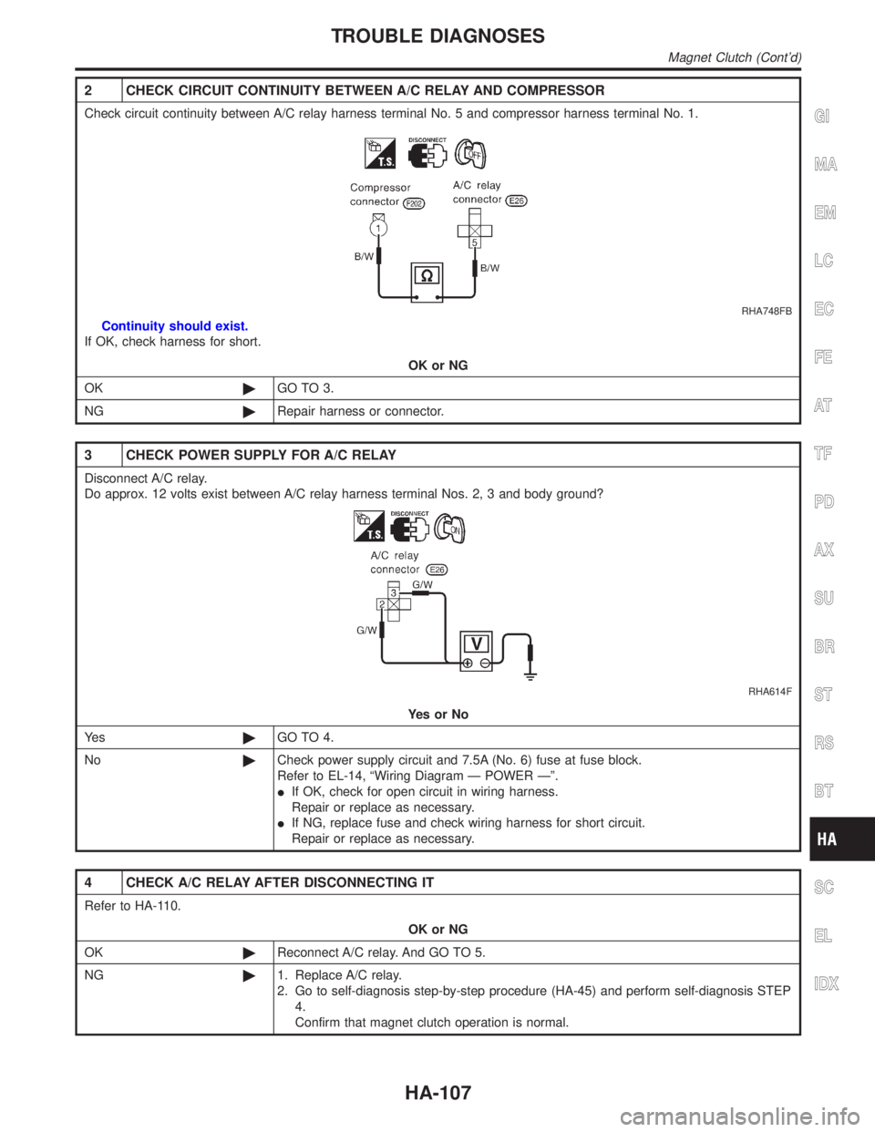
2 CHECK CIRCUIT CONTINUITY BETWEEN A/C RELAY AND COMPRESSOR
Check circuit continuity between A/C relay harness terminal No. 5 and compressor harness terminal No. 1.
RHA748FB
Continuity should exist.
If OK, check harness for short.
OK or NG
OK©GO TO 3.
NG©Repair harness or connector.
3 CHECK POWER SUPPLY FOR A/C RELAY
Disconnect A/C relay.
Do approx. 12 volts exist between A/C relay harness terminal Nos. 2, 3 and body ground?
RHA614F
YesorNo
Ye s©GO TO 4.
No©Check power supply circuit and 7.5A (No. 6) fuse at fuse block.
Refer to EL-14, ªWiring Diagram Ð POWER к.
IIf OK, check for open circuit in wiring harness.
Repair or replace as necessary.
IIf NG, replace fuse and check wiring harness for short circuit.
Repair or replace as necessary.
4 CHECK A/C RELAY AFTER DISCONNECTING IT
Refer to HA-110.
OK or NG
OK©Reconnect A/C relay. And GO TO 5.
NG©1. Replace A/C relay.
2. Go to self-diagnosis step-by-step procedure (HA-45) and perform self-diagnosis STEP
4.
Confirm that magnet clutch operation is normal.
GI
MA
EM
LC
EC
FE
AT
TF
PD
AX
SU
BR
ST
RS
BT
SC
EL
IDX
TROUBLE DIAGNOSES
Magnet Clutch (Cont'd)
HA-107
Page 1963 of 2395
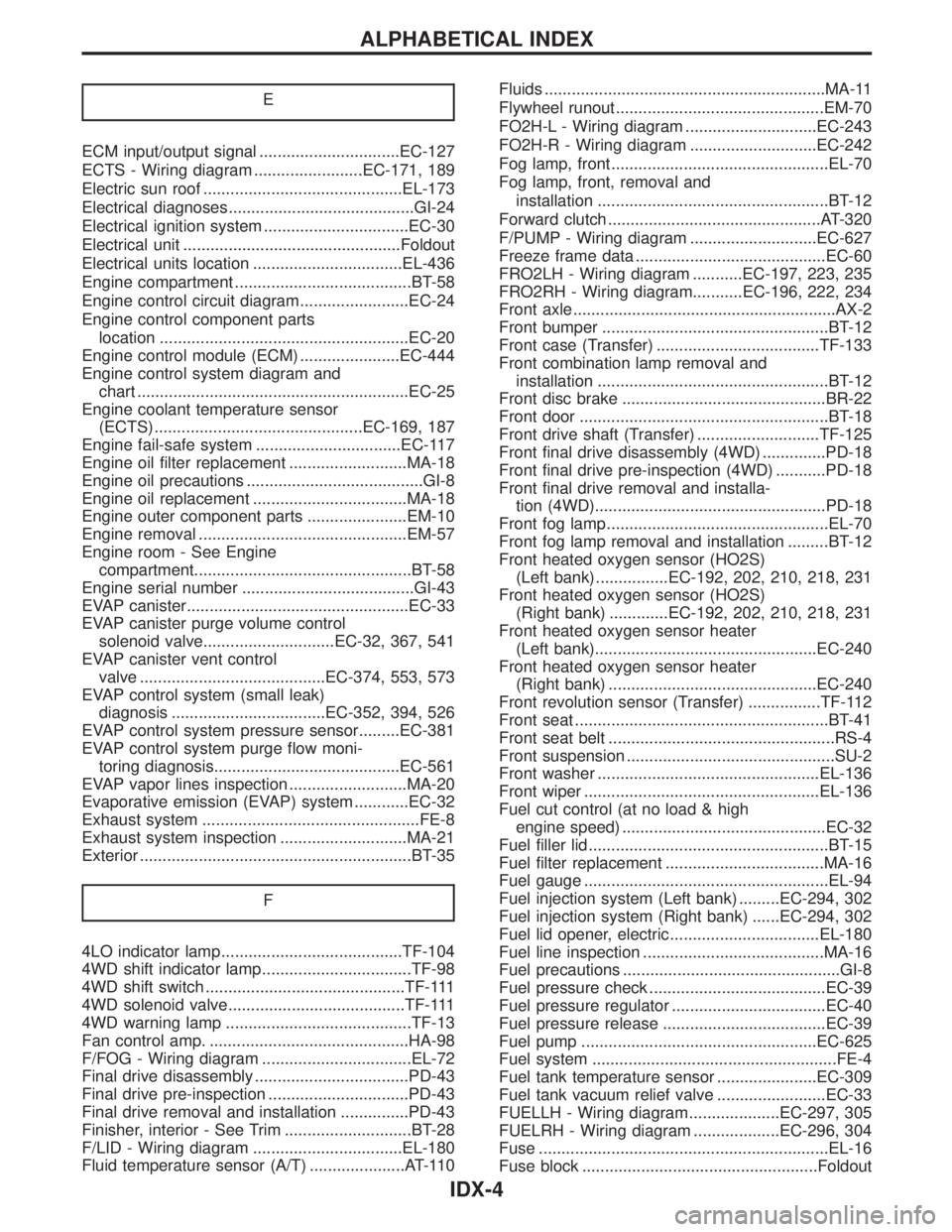
E
ECM input/output signal ...............................EC-127
ECTS - Wiring diagram ........................EC-171, 189
Electric sun roof ............................................EL-173
Electrical diagnoses.........................................GI-24
Electrical ignition system ................................EC-30
Electrical unit ................................................Foldout
Electrical units location .................................EL-436
Engine compartment .......................................BT-58
Engine control circuit diagram........................EC-24
Engine control component parts
location .......................................................EC-20
Engine control module (ECM) ......................EC-444
Engine control system diagram and
chart ............................................................EC-25
Engine coolant temperature sensor
(ECTS) ..............................................EC-169, 187
Engine fail-safe system ................................EC-117
Engine oil filter replacement ..........................MA-18
Engine oil precautions .......................................GI-8
Engine oil replacement ..................................MA-18
Engine outer component parts ......................EM-10
Engine removal ..............................................EM-57
Engine room - See Engine
compartment................................................BT-58
Engine serial number ......................................GI-43
EVAP canister.................................................EC-33
EVAP canister purge volume control
solenoid valve.............................EC-32, 367, 541
EVAP canister vent control
valve .........................................EC-374, 553, 573
EVAP control system (small leak)
diagnosis ..................................EC-352, 394, 526
EVAP control system pressure sensor.........EC-381
EVAP control system purge flow moni-
toring diagnosis.........................................EC-561
EVAP vapor lines inspection ..........................MA-20
Evaporative emission (EVAP) system ............EC-32
Exhaust system ................................................FE-8
Exhaust system inspection ............................MA-21
Exterior ............................................................BT-35
F
4LO indicator lamp........................................TF-104
4WD shift indicator lamp.................................TF-98
4WD shift switch ............................................TF-111
4WD solenoid valve.......................................TF-111
4WD warning lamp .........................................TF-13
Fan control amp. ............................................HA-98
F/FOG - Wiring diagram .................................EL-72
Final drive disassembly ..................................PD-43
Final drive pre-inspection ...............................PD-43
Final drive removal and installation ...............PD-43
Finisher, interior - See Trim ............................BT-28
F/LID - Wiring diagram .................................EL-180
Fluid temperature sensor (A/T) .....................AT-110Fluids ..............................................................MA-11
Flywheel runout..............................................EM-70
FO2H-L - Wiring diagram .............................EC-243
FO2H-R - Wiring diagram ............................EC-242
Fog lamp, front................................................EL-70
Fog lamp, front, removal and
installation ...................................................BT-12
Forward clutch ...............................................AT-320
F/PUMP - Wiring diagram ............................EC-627
Freeze frame data ..........................................EC-60
FRO2LH - Wiring diagram ...........EC-197, 223, 235
FRO2RH - Wiring diagram...........EC-196, 222, 234
Front axle..........................................................AX-2
Front bumper ..................................................BT-12
Front case (Transfer) ....................................TF-133
Front combination lamp removal and
installation ...................................................BT-12
Front disc brake .............................................BR-22
Front door .......................................................BT-18
Front drive shaft (Transfer) ...........................TF-125
Front final drive disassembly (4WD) ..............PD-18
Front final drive pre-inspection (4WD) ...........PD-18
Front final drive removal and installa-
tion (4WD)...................................................PD-18
Front fog lamp.................................................EL-70
Front fog lamp removal and installation .........BT-12
Front heated oxygen sensor (HO2S)
(Left bank) ................EC-192, 202, 210, 218, 231
Front heated oxygen sensor (HO2S)
(Right bank) .............EC-192, 202, 210, 218, 231
Front heated oxygen sensor heater
(Left bank).................................................EC-240
Front heated oxygen sensor heater
(Right bank) ..............................................EC-240
Front revolution sensor (Transfer) ................TF-112
Front seat ........................................................BT-41
Front seat belt ..................................................RS-4
Front suspension ..............................................SU-2
Front washer .................................................EL-136
Front wiper ....................................................EL-136
Fuel cut control (at no load & high
engine speed) .............................................EC-32
Fuel filler lid.....................................................BT-15
Fuel filter replacement ...................................MA-16
Fuel gauge ......................................................EL-94
Fuel injection system (Left bank) .........EC-294, 302
Fuel injection system (Right bank) ......EC-294, 302
Fuel lid opener, electric.................................EL-180
Fuel line inspection ........................................MA-16
Fuel precautions ................................................GI-8
Fuel pressure check .......................................EC-39
Fuel pressure regulator ..................................EC-40
Fuel pressure release ....................................EC-39
Fuel pump ....................................................EC-625
Fuel system ......................................................FE-4
Fuel tank temperature sensor ......................EC-309
Fuel tank vacuum relief valve ........................EC-33
FUELLH - Wiring diagram....................EC-297, 305
FUELRH - Wiring diagram ...................EC-296, 304
Fuse ................................................................EL-16
Fuse block ....................................................Foldout
ALPHABETICAL INDEX
IDX-4