Page 849 of 2395

On Board Diagnosis LogicNBEC0610This diagnosis checks whether the engine coolant temperature is
extraordinary high, even when the load is not heavy.
When malfunction is detected, the malfunction indicator lamp (MIL)
will light up even in the first trip.
Malfunction is detected when engine coolant temperature is exces-
sively high under normal engine speed.
Possible CauseNBEC0611IThermostat
IImproper ignition timing
IEngine coolant temperature sensor
IBlocked radiator
IBlocked front end (Improper fitting of nose mask)
ICrushed vehicle frontal area (Vehicle frontal is collided but not
repaired)
IBlocked air passage by improper installation of front fog lamp
or fog lamps.
IImproper mixture ratio of coolant
IDamaged bumper
For more information, refer to ªMAIN 12 CAUSES OF
OVERHEATINGº, EC-319.
Overall Function CheckNBEC0612Use this procedure to check the overall function of the coolant
overtemperature enrichment protection check, a DTC might not be
confirmed.
WARNING:
Never remove the radiator cap when the engine is hot. Serious
burns could be caused by high-pressure fluid escaping from
the radiator.
Wrap a thick cloth around the cap. Carefully remove the cap
by turning it a quarter turn to allow built-up pressure to
escape. Then turn the cap all the way off.
SEF621W
WITH CONSULT-IINBEC0612S011) Check the coolant level and mixture ratio (using coolant tester)
in the reservoir tank and radiator.
Allow engine to cool before checking coolant level and
mixture ratio.
IIf the coolant level in the reservoir and/or radiator is below the
proper range, go to ªDiagnostic Procedureº, EC-316.
IIf the coolant mixture ratio is out of the range of 45 to 55%,
replace the coolant in the following procedure MA-14, ªChang-
ing Engine Coolantº.
a) Fill radiator with coolant up to specified level with a filling speed
DTC P0217 COOLANT OVERTEMPERATURE ENRICHMENT PROTECTION
On Board Diagnosis Logic
EC-314
Page 962 of 2395

3 CHECK IACV-AAC VALVE OUTPUT SIGNAL CIRCUIT FOR OPEN AND SHORT
1. Turn ignition switch ªOFFº.
2. Disconnect ECM harness connector.
3. Check harness continuity between ECM terminals and IACV-AAC valve terminals as follows.
Refer to Wiring Diagram.
MTBL0354
Continuity should exist.
4. Also check harness for short to ground and short to power.
OK or NG
OK©GO TO 5.
NG©GO TO 4.
4 DETECT MALFUNCTIONING PART
Check the following.
IHarness connectors F101, F6
IHarness for open or short between IACV-AAC valve and ECM
©Repair harness connectors.
5 CHECK AIR CONTROL VALVE (POWER STEERING) OPERATION-I
1. Reconnect ECM harness connector and IACV-AAC valve harness connector.
2. Disconnect vacuum hose connected to air control valve (Power steering) at intake air duct.
3. Start engine and let it idle.
4. Check vacuum hose for vacuum existence.
SEF995Y
Vacuum slightly exists or does not exist.
OK or NG
OK©GO TO 6.
NG©Replace air control valve (Power steering).
GI
MA
EM
LC
FE
AT
TF
PD
AX
SU
BR
ST
RS
BT
HA
SC
EL
IDX
DTC P0505 IDLE AIR CONTROL VALVE (IACV) Ð AUXILIARY AIR CONTROL
(AAC) VALVE
Diagnostic Procedure (Cont'd)
EC-427
Page 967 of 2395

SEF197Y
SEF198Y
DTC Confirmation ProcedureNBEC0260CAUTION:
Always drive vehicle at a safe speed.
NOTE:
If ªDTC Confirmation Procedureº has been previously conducted,
always turn ignition switch ªOFFº and wait at least 10 seconds
before conducting the next test.
WITH CONSULT-IINBEC0260S011) Start engine and warm it up to normal operating temperature.
2) Turn ignition switch ªOFFº, wait at least 10 seconds and then
start engine.
3) Select ªCLSD THL/P SWº in ªDATA MONITORº mode.
If ªCLSD THL/P SWº is not available, go to step 5.
4) Check the signal under the following conditions.
Condition Signal indication
Throttle valve: Idle position ON
Throttle valve: Slightly open OFF
If the result is NG, go to ªDiagnostic Procedureº, EC-435.
If OK, go to following step.
5) Select ªDATA MONITORº mode with CONSULT-II.
6) Drive the vehicle for at least 5 consecutive seconds under the
following condition.
THRTL POS SEN More than 2.5V
VHCL SPEED SE More than 5 km/h (3 MPH)
Selector lever Suitable position
Driving locationDriving vehicle uphill (Increased engine load)
will help maintain the driving conditions
required for this test.
7) If 1st trip DTC is detected, go to ªDiagnostic Procedureº,
EC-435.
SEF345X
Overall Function CheckNBEC0261Use this procedure to check the overall function of the closed
throttle position switch circuit. During this check, a 1st trip DTC
might not be confirmed.
WITH GSTNBEC0261S011) Start engine and warm it up to normal operating temperature.
2) Check the voltage between ECM terminal 56 (Closed throttle
position switch signal) and ground under the following condi-
tions.
At idle: Battery voltage
DTC P0510 CLOSED THROTTLE POSITION SWITCH
DTC Confirmation Procedure
EC-432
Page 1181 of 2395

4 CHECK REAR WINDOW DEFOGGER INPUT SIGNAL CIRCUIT FOR OPEN OR SHORT
1. Stop engine.
2. Disconnect ECM harness connector.
3. Disconnect rear window defogger relay.
4. Check harness continuity between ECM terminal 52 and rear window defogger relay terminals 7.
SEF031Z
5. Also check harness for short to ground and short to power.
OK or NG
OK©GO TO 6.
NG©GO TO 5.
5 DETECT MALFUNCTIONING PART
Check the following.
IHarness connectors E1, M1
IHarness connectors M33, F22
IDiode M37
IHarness for open and short between ECM and rear window defigger relay
©Repair open circuit or short to ground or short to power in harness or connectors.
6 CHECK INTERMITTENT INCIDENT
Perform ªTROUBLE DIAGNOSIS FOR INTERMITTENT INCIDENTº, EC-140.
©INSPECTION END
7 CHECK HEADLAMP FUNCTION
1. Start engine.
2. Turn the lighting switch ªONº at 1st position with high beam.
3. Check that headlamps are illuminated.
OK or NG
OK©GO TO 8.
NG©Refer to EL-60, ªHEADLAMP (FOR USA)º or EL-123, ªHEADLAMP (FOR CANADA) Ð
DAYTIME LIGHT SYSTEMº.
ELECTRICAL LOAD SIGNAL
Diagnostic Procedure (Cont'd)
EC-646
Page 1182 of 2395
8 CHECK HEADLAMP INPUT SIGNAL CIRCUIT FOR OPEN OR SHORT
1. Stop engine.
2. Disconnect ECM harness connector.
3. Disconnect headlamp LH relay.
4. Check harness continuity between ECM terminal 52 and headlamp LH relay terminal 7 under the following conditions.
SEF031Z
5. Also check harness for short to ground and short to power.
OK or NG
OK©GO TO 10.
NG©GO TO 9.
9 DETECT MALFUNCTIONING PART
Check the following.
IHarness connectors E1, M1
IHarness connectors M33, F22
IDiode E121
IHarness for open and short between ECM and headlamp LH relay or daytime light control unit
©Repair open circuit or short to ground or short to power in harness or connectors.
10 CHECK INTERMITTENT INCIDENT
Perform ªTROUBLE DIAGNOSIS FOR INTERMITTENT INCIDENTº, EC-140.
©INSPECTION END
GI
MA
EM
LC
FE
AT
TF
PD
AX
SU
BR
ST
RS
BT
HA
SC
EL
IDX
ELECTRICAL LOAD SIGNAL
Diagnostic Procedure (Cont'd)
EC-647
Page 1520 of 2395

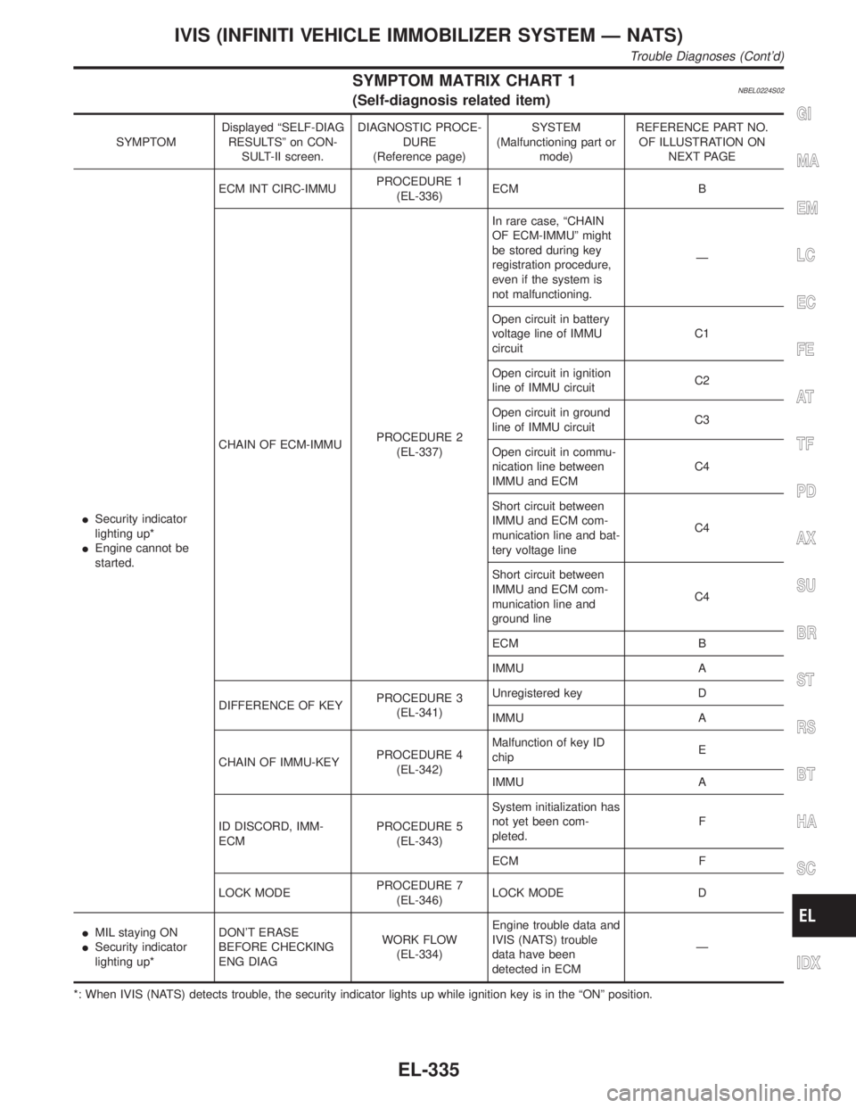
SYMPTOM MATRIX CHART 1NBEL0224S02(Self-diagnosis related item)
SYMPTOMDisplayed ªSELF-DIAG
RESULTSº on CON-
SULT-II screen.DIAGNOSTIC PROCE-
DURE
(Reference page)SYSTEM
(Malfunctioning part or
mode)REFERENCE PART NO.
OF ILLUSTRATION ON
NEXT PAGE
ISecurity indicator
lighting up*
IEngine cannot be
started.ECM INT CIRC-IMMUPROCEDURE 1
(EL-336)ECM B
CHAIN OF ECM-IMMUPROCEDURE 2
(EL-337)In rare case, ªCHAIN
OF ECM-IMMUº might
be stored during key
registration procedure,
even if the system is
not malfunctioning.Ð
Open circuit in battery
voltage line of IMMU
circuitC1
Open circuit in ignition
line of IMMU circuitC2
Open circuit in ground
line of IMMU circuitC3
Open circuit in commu-
nication line between
IMMU and ECMC4
Short circuit between
IMMU and ECM com-
munication line and bat-
tery voltage lineC4
Short circuit between
IMMU and ECM com-
munication line and
ground lineC4
ECM B
IMMU A
DIFFERENCE OF KEYPROCEDURE 3
(EL-341)Unregistered key D
IMMU A
CHAIN OF IMMU-KEYPROCEDURE 4
(EL-342)Malfunction of key ID
chipE
IMMU A
ID DISCORD, IMM-
ECMPROCEDURE 5
(EL-343)System initialization has
not yet been com-
pleted.F
ECM F
LOCK MODEPROCEDURE 7
(EL-346)LOCK MODE D
IMIL staying ON
ISecurity indicator
lighting up*DON'T ERASE
BEFORE CHECKING
ENG DIAGWORK FLOW
(EL-334)Engine trouble data and
IVIS (NATS) trouble
data have been
detected in ECMÐ
*: When IVIS (NATS) detects trouble, the security indicator lights up while ignition key is in the ªONº position.
GI
MA
EM
LC
EC
FE
AT
TF
PD
AX
SU
BR
ST
RS
BT
HA
SC
IDX
IVIS (INFINITI VEHICLE IMMOBILIZER SYSTEM Ð NATS)
Trouble Diagnoses (Cont'd)
EL-335
Page 1529 of 2395
![INFINITI QX4 2001 Factory Service Manual DIAGNOSTIC PROCEDURE 6=NBEL0224S10ªSECURITY INDICATOR LAMP DOES NOT LIGHT UPº
1 CHECK FUSE
Check 10A fuse [No. 12, located in the fuse block (J/B)].
Is 10A fuse OK?
Ye s©GO TO 2.
No©Replace fuse.
INFINITI QX4 2001 Factory Service Manual DIAGNOSTIC PROCEDURE 6=NBEL0224S10ªSECURITY INDICATOR LAMP DOES NOT LIGHT UPº
1 CHECK FUSE
Check 10A fuse [No. 12, located in the fuse block (J/B)].
Is 10A fuse OK?
Ye s©GO TO 2.
No©Replace fuse.](/manual-img/42/57027/w960_57027-1528.png)
DIAGNOSTIC PROCEDURE 6=NBEL0224S10ªSECURITY INDICATOR LAMP DOES NOT LIGHT UPº
1 CHECK FUSE
Check 10A fuse [No. 12, located in the fuse block (J/B)].
Is 10A fuse OK?
Ye s©GO TO 2.
No©Replace fuse.
2 CHECK SECURITY INDICATOR LAMP
1. Install 10A fuse.
2. Perform initialization with CONSULT-II.
For initialization, refer to ªCONSULT-II Operation Manual IVIS/NVISº.
3. Turn ignition switch OFF.
4. Start engine and turn ignition switch OFF.
5. Check the security indicator lamp lighting.
Security indicator lamp should be blinking.
OK or NG
OK©INSPECTION END
NG©GO TO 3.
3 CHECK SECURITY INDICATOR LAMP POWER SUPPLY CIRCUIT
1. Disconnect security indicator lamp connector.
2. Check voltage between security indicator lamp connector terminal 1 and ground.
SEL370X
OK or NG
OK©GO TO 4.
NG©Check harness for open or short between fuse and security indicator lamp.
4 CHECK SECURITY INDICATOR LAMP
Check security Indicator Lamp.
Is security indicator lamp OK?
Ye s©GO TO 5.
No©Replace security indicator lamp.
IVIS (INFINITI VEHICLE IMMOBILIZER SYSTEM Ð NATS)
Trouble Diagnoses (Cont'd)
EL-344
Page 1589 of 2395

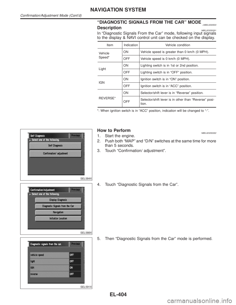
ªDIAGNOSTIC SIGNALS FROM THE CARº MODE=NBEL0232S03DescriptionNBEL0232S0301In ªDiagnostic Signals From the Carº mode, following input signals
to the display & NAVI control unit can be checked on the display.
Item Indication Vehicle condition
Vehicle
Speed*ON Vehicle speed is greater than 0 km/h (0 MPH).
OFF Vehicle speed is 0 km/h (0 MPH).
LightON Lighting switch is in 1st or 2nd position.
OFF Lighting switch is in ªOFFº position.
IGNON Ignition switch is in ªONº position.
OFF Ignition switch is in ªACCº position.
REVERSE*ON Selector/shift lever is in ªReverseº position.
OFFSelector/shift lever is in other than ªReverseº posi-
tion.
*: When ignition switch is in ªACCº position, indication will be changed to ª-º.
SEL584X
How to PerformNBEL0232S03021. Start the engine.
2. Push both ªMAPº and ªD/Nº switches at the same time for more
than 5 seconds.
3. Touch ªConfirmation/ adjustmentº.
SEL588X
4. Touch ªDiagnostic Signals from the Carº.
SEL591X
5. Then ªDiagnostic Signals from the Carº mode is performed.
NAVIGATION SYSTEM
Confirmation/Adjustment Mode (Cont'd)
EL-404