2001 INFINITI QX4 wheel torque
[x] Cancel search: wheel torquePage 1967 of 2395
S/VCSW - Wiring diagram ...........................EC-493
Swirl control valve control solenoid
valve .........................................................EC-458
Swirl control valve control vacuum
check switch .............................................EC-493
SWL/V - Wiring diagram ..............................EC-458
Symbols and abbreviations .............................GI-10
Symptom matrix chart...................................EC-118
System readiness test (SRT) code ................EC-61
T
2-4WD shift solenoid valve............................TF-111
Tachometer .....................................................EL-94
Tail lamp ..........................................................EL-61
TAIL/L - Wiring diagram ..................................EL-63
TCM circuit diagram ........................................AT-13
TCM inspection table ......................................AT-92
TFTS - Wiring diagram .................................EC-311
THEFT - Wiring diagram ...............................EL-300
Theft warning system....................................EL-294
Thermometer .................................................EL-110
Thermostat ......................................................LC-16
Three way catalyst function (Left bank) .......EC-347
Three way catalyst function (Right
bank) .........................................................EC-347
Three way catalyst precautions.........................GI-6
Throttle bodies ...............................................EM-12
Throttle position sensor (TPS) .....................EC-174
Throttle position sensor adjustment .............EC-101
Throttle position switch ...........EC-431, AT-184, 264
Tie-rod .............................................................ST-21
Tie-rod ball joints.............................................ST-21
Tightening torque of standard bolts.................GI-50
Timing chain ...................................................EM-20
Tire rotation ....................................................MA-24
Tire size ...........................................................GI-44
TLID - Wiring diagram ..................................EL-179
Tooth contact (front final drive 4WD) .............PD-29
Tooth contact diff. ...........................................PD-56
Torque converter installation .........................AT-278
Torque convertor clutch solenoid
valve ..................................................AT-152, 161
Tow truck towing ..............................................GI-47
Towing point.....................................................GI-49
TP/SW - Wiring diagram ..............................EC-434
TPS - Wiring diagram...................................EC-180
Transfer control unit inspection table..............TF-55
Transfer dropping resistor .............................TF-112
Transfer fluid replacement (Part time
4WD model) ...............................................MA-22
Transfer fluid temperature sensor .................TF-111
Transfer motor ...............................................TF-117
Transfer motor relay ......................................TF-113
Transfer serial number ....................................GI-43
TRANSMT - Wiring diagram .........................EL-325
Tread-FR&RR (Dimensions)............................GI-43
Trim .................................................................BT-28
Trouble diagnoses ...........................................GI-34
Trunk lid opener, electric...............................EL-178Turbine revolution sensor..............................AT-202
TURN - Wiring diagram ..................................EL-77
Turn signal lamp .............................................EL-75
Two trip detection logic ..................................EC-59
Two-pole lift .....................................................GI-47
U
Under body .....................................................BT-60
V
Vacuum cut valve ...........................................EC-32
Vacuum cut valve bypass valve.....EC-32, 585, 591
Vacuum hose (brake system).........................BR-21
Vacuum hose drawing (Engine control) .........EC-26
Valve clearance ..............................................EM-52
Valve guide.....................................................EM-43
Valve seat.......................................................EM-45
Valve spring....................................................EM-46
Vehicle identification number...........................GI-42
Vehicle recovery (freeing a stuck
vehicle) .........................................................GI-49
Vehicle speed sensor (VSS) ........................EC-417
VENT/V - Wiring diagram ............EC-376, 555, 576
Ventilation air filter ........................................HA-159
VIAS .............................................................EC-610
VIAS - Wiring diagram .................................EC-610
Viscosity number (SAE) .................................MA-12
VSS - Wiring diagram ..................................EC-420
W
Wait detection switch ....................................TF-112
WARN - Wiring diagram................................EL-115
Warning chime ..............................................EL-125
Warning lamps ..............................................EL-114
Washer, front .................................................EL-136
Washer, rear..................................................EL-141
Water pump ....................................................LC-12
Water temperature gauge ...............................EL-94
Weatherstrip - See Exterior ............................BT-35
Wheel balance ...............................................MA-24
Wheel bearing (front)........................................AX-4
Wheel bearing (rear) ......................................AX-18
Wheel hub (front)..............................................AX-6
Wheel sensors (ABS)...............................BR-56, 80
Wheel size .......................................................GI-44
Wheelarch height .............................................SU-5
Wheelbase (Dimensions) ................................GI-43
Wide open & closed throttle position
switch ........................................................EC-174
Width (Dimensions) .........................................GI-43
WINDOW - Wiring diagram ..........................EL-245
Window, door ..................................................BT-18
Window, rear side ...........................................BT-55
Window, side - See Rear side window ...........BT-55
ALPHABETICAL INDEX
IDX-8
Page 2028 of 2395
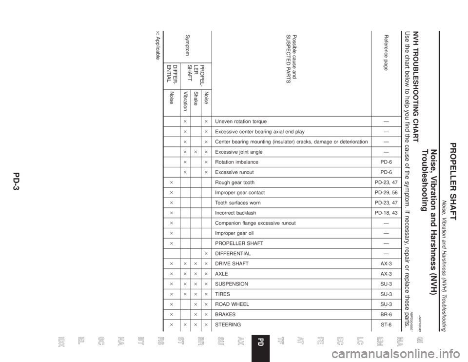
Noise, Vibration and Harshness (NVH)
Troubleshooting
=NBPD0049NVH TROUBLESHOOTING CHARTNBPD0049S01Use the chart below to help you find the cause of the symptom. If necessary, repair or replace these parts.
Reference pageÐ
Ð
Ð
Ð
PD-6
PD-6
PD-23, 47
PD-29, 56
PD-23, 47
PD-18, 43
Ð
Ð
Ð
Ð
AX-3
AX-3
SU-3
SU-3
SU-3
BR-6
ST-6
Possible cause and
SUSPECTED PARTS
Uneven rotation torque
Excessive center bearing axial end play
Center bearing mounting (insulator) cracks, damage or deterioration
Excessive joint angle
Rotation imbalance
Excessive runout
Rough gear tooth
Improper gear contact
Tooth surfaces worn
Incorrect backlash
Companion flange excessive runout
Improper gear oil
PROPELLER SHAFT
DIFFERENTIAL
DRIVE SHAFT
AXLE
SUSPENSION
TIRES
ROAD WHEEL
BRAKES
STEERING
SymptomPROPEL-
LER
SHAFTNoise´´´´´´ ´´´´´´´´
Shake´ ´´´´´´´
Vibration´´´´´´ ´´´´ ´
DIFFER-
ENTIALNoise´´´´´´´ ´´´´´´´
´: Applicable
GI
MA
EM
LC
EC
FE
AT
TF
AX
SU
BR
ST
RS
BT
HA
SC
EL
IDX
PROPELLER SHAFT
Noise, Vibration and Harshness (NVH) Troubleshooting
PD-3
Page 2184 of 2395
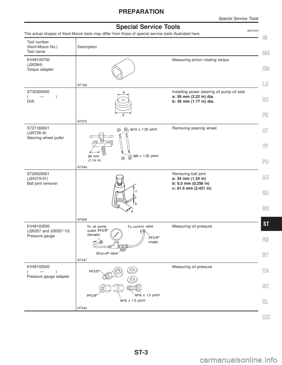
Special Service ToolsNBST0003The actual shapes of Kent-Moore tools may differ from those of special service tools illustrated here.
Tool number
(Kent-Moore No.)
Tool nameDescription
KV48100700
(J26364)
Torque adapter
NT169
Measuring pinion rotating torque
ST35300000
(Ð)
Drift
NT073
Installing power steering oil pump oil seal
a: 59 mm (2.32 in) dia.
b: 45 mm (1.77 in) dia.
ST27180001
(J25726-A)
Steering wheel puller
NT544
Removing steering wheel
ST29020001
(J24319-01)
Ball joint remover
NT694
Removing ball joint
a: 34 mm (1.34 in)
b: 6.5 mm (0.256 in)
c: 61.5 mm (2.421 in)
KV48103500
(J26357 and J26357-10)
Pressure gauge
NT547
Measuring oil pressure
KV48102500
(Ð)
Pressure gauge adapter
NT542
Measuring oil pressure
GI
MA
EM
LC
EC
FE
AT
TF
PD
AX
SU
BR
RS
BT
HA
SC
EL
IDX
PREPARATION
Special Service Tools
ST-3
Page 2185 of 2395
Tool number
(Kent-Moore No.)
Tool nameDescription
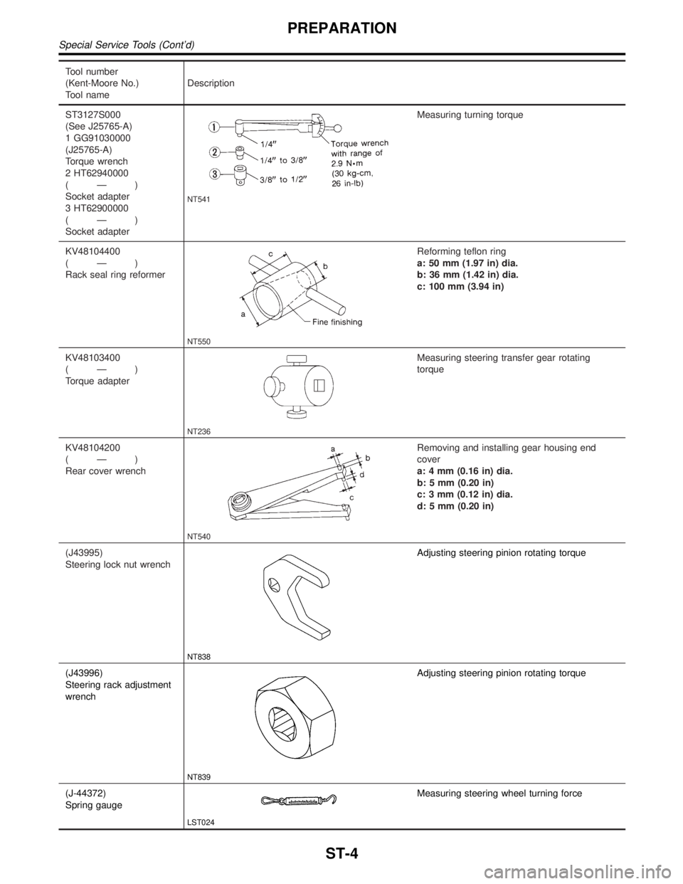
ST3127S000
(See J25765-A)
1 GG91030000
(J25765-A)
Torque wrench
2 HT62940000
(Ð)
Socket adapter
3 HT62900000
(Ð)
Socket adapter
NT541
Measuring turning torque
KV48104400
(Ð)
Rack seal ring reformer
NT550
Reforming teflon ring
a: 50 mm (1.97 in) dia.
b: 36 mm (1.42 in) dia.
c: 100 mm (3.94 in)
KV48103400
(Ð)
Torque adapter
NT236
Measuring steering transfer gear rotating
torque
KV48104200
(Ð)
Rear cover wrench
NT540
Removing and installing gear housing end
cover
a: 4 mm (0.16 in) dia.
b: 5 mm (0.20 in)
c: 3 mm (0.12 in) dia.
d: 5 mm (0.20 in)
(J43995)
Steering lock nut wrench
NT838
Adjusting steering pinion rotating torque
(J43996)
Steering rack adjustment
wrench
NT839
Adjusting steering pinion rotating torque
(J-44372)
Spring gauge
LST024
Measuring steering wheel turning force
PREPARATION
Special Service Tools (Cont'd)
ST-4
Page 2187 of 2395
NBST0043
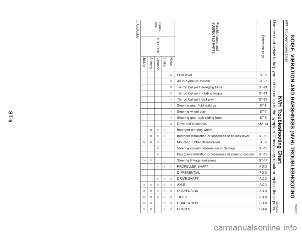
NVH Troubleshooting ChartNBST0043S01Use the chart below to help you find the cause of the symptom. If necessary, repair or replace these parts.
Reference pageST-8
ST-9
ST-21
ST-21
ST-21
ST-8
ST-7
ST-9
MA-13
Ð
ST-13
ST-8
ST-13
ST-13
ST-17
PD-3
PD-3
AX-3
AX-3
SU-3
SU-3
SU-3
BR-6
Possible cause and
SUSPECTED PARTS
Fluid level
Air in hydraulic system
Tie-rod ball joint swinging force
Tie-rod ball joint rotating torque
Tie-rod ball joint end play
Steering gear fluid leakage
Steering wheel play
Steering gear rack sliding force
Drive belt looseness
Improper steering wheel
Improper installation or looseness or tilt lock lever
Mounting rubber deterioration
Steering column deformation or damage
Improper installation or looseness of steering column
Steering linkage looseness
PROPELLER SHAFT
DIFFERENTIAL
DRIVE SHAFT
AXLE
SUSPENSION
TIRES
ROAD WHEEL
BRAKES
Symp-
tomSTEERINGNoise´´´´´´´´´ ´´´´´´´´
Shake´´´ ´ ´´´´´´
Vibration´´´´´ ´ ´´´´
Shimmy´´´ ´ ´´´´´
Judder´ ´ ´´´´´
´: Applicable
NOISE, VIBRATION AND HARSHNESS (NVH) TROUBLESHOOTING
NVH Troubleshooting Chart
ST-6
Page 2197 of 2395
SST847C
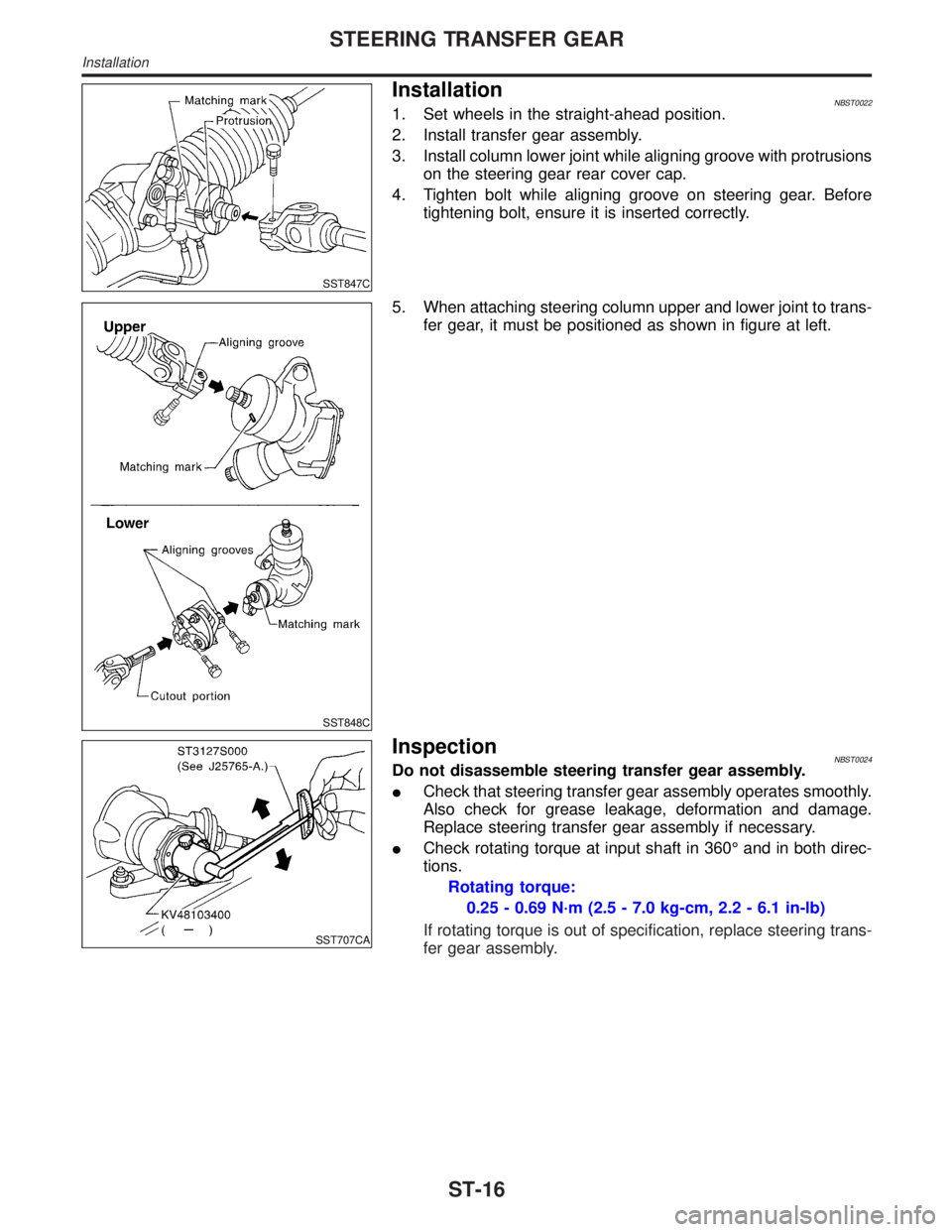
InstallationNBST00221. Set wheels in the straight-ahead position.
2. Install transfer gear assembly.
3. Install column lower joint while aligning groove with protrusions
on the steering gear rear cover cap.
4. Tighten bolt while aligning groove on steering gear. Before
tightening bolt, ensure it is inserted correctly.
SST848C
5. When attaching steering column upper and lower joint to trans-
fer gear, it must be positioned as shown in figure at left.
SST707CA
InspectionNBST0024Do not disassemble steering transfer gear assembly.
ICheck that steering transfer gear assembly operates smoothly.
Also check for grease leakage, deformation and damage.
Replace steering transfer gear assembly if necessary.
ICheck rotating torque at input shaft in 360É and in both direc-
tions.
Rotating torque:
0.25 - 0.69 N´m (2.5 - 7.0 kg-cm, 2.2 - 6.1 in-lb)
If rotating torque is out of specification, replace steering trans-
fer gear assembly.
STEERING TRANSFER GEAR
Installation
ST-16
Page 2199 of 2395
Removal and InstallationNBST0027
SST614C
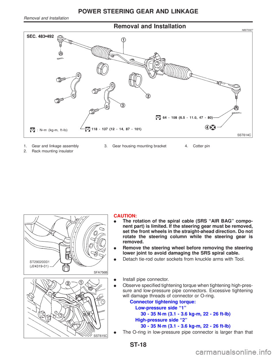
1. Gear and linkage assembly
2. Rack mounting insulator3. Gear housing mounting bracket 4. Cotter pin
SFA756B
CAUTION:
IThe rotation of the spiral cable (SRS ªAIR BAGº compo-
nent part) is limited. If the steering gear must be removed,
set the front wheels in the straight-ahead direction. Do not
rotate the steering column while the steering gear is
removed.
IRemove the steering wheel before removing the steering
lower joint to avoid damaging the SRS spiral cable.
IDetach tie-rod outer sockets from knuckle arms with Tool.
SST615C
IInstall pipe connector.
IObserve specified tightening torque when tightening high-pres-
sure and low-pressure pipe connectors. Excessive tightening
will damage threads of connector or O-ring.
Connector tightening torque:
Low-pressure side ª1º
30 - 35 N´m (3.1 - 3.6 kg-m, 22 - 26 ft-lb)
High-pressure side ª2º
30 - 35 N´m (3.1 - 3.6 kg-m, 22 - 26 ft-lb)
IThe O-ring in low-pressure pipe connector is larger than that
POWER STEERING GEAR AND LINKAGE
Removal and Installation
ST-18
Page 2200 of 2395
in high-pressure connector. Take care to install the proper
O-ring.
SST616C
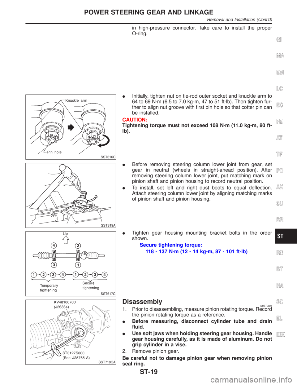
IInitially, tighten nut on tie-rod outer socket and knuckle arm to
64 to 69 N´m (6.5 to 7.0 kg-m, 47 to 51 ft-lb). Then tighten fur-
ther to align nut groove with first pin hole so that cotter pin can
be installed.
CAUTION:
Tightening torque must not exceed 108 N´m (11.0 kg-m, 80 ft-
lb).
SST819A
IBefore removing steering column lower joint from gear, set
gear in neutral (wheels in straight-ahead position). After
removing steering column lower joint, put matching mark on
pinion shaft and pinion housing to record neutral position.
ITo install, set left and right dust boots to equal deflection.
Attach steering column lower joint by aligning matching marks
of pinion shaft and pinion housing.
SST617C
ITighten gear housing mounting bracket bolts in the order
shown.
Secure tightening torque:
118 - 137 N´m (12 - 14 kg-m, 87 - 101 ft-lb)
SST718CA
DisassemblyNBST00281. Prior to disassembling, measure pinion rotating torque. Record
the pinion rotating torque as a reference.
IBefore measuring, disconnect cylinder tube and drain
fluid.
IUse soft jaws when holding steering gear housing. Handle
gear housing carefully, as it is made of aluminum. Do not
grip cylinder in a vise.
2. Remove pinion gear.
Be careful not to damage pinion gear when removing pinion
seal ring.
GI
MA
EM
LC
EC
FE
AT
TF
PD
AX
SU
BR
RS
BT
HA
SC
EL
IDX
POWER STEERING GEAR AND LINKAGE
Removal and Installation (Cont'd)
ST-19