2001 INFINITI QX4 tensioner
[x] Cancel search: tensionerPage 1676 of 2395

SEM439G
SEM440G
17. Install RH and LH rocker covers.
Rocker cover tightening procedure:
ITighten in numerical order as shown in the figure.
a. Tighten bolts 1 to 10 in that order to 6.9 to 8.8 N´m (0.7 to 0.9
kg-m, 61 to 78 in-lb).
b. Then tighten bolts 1 to 10 as indicated in figure to 6.9 to 8.8
N´m (0.7 to 0.9 kg-m, 61 to 78 in-lb).
18. Hang engine using the right and left side engine slingers with
a suitable hoist.
19. Set a suitable transmission jack under the suspension mem-
ber.
20. Remove right and left side engine mounting nuts.
21. Remove right and left side suspension member bolts.
22. Install aluminum oil pan. Refer to EM-18, ªInstallationº.
23. Set ring gear stopper using the mounting bolt hole.
IBe careful not to damage the signal plate teeth.
SEM417G
24. Install crankshaft pulley to crankshaft.
IAlign pointer with TDC mark on crankshaft pulley.
SEM531G
25. Install crankshaft pulley bolt.
ILubricate thread and seat surface of the bolt with new
engine oil.
a. Tighten to 39 to 49 N´m (4.0 to 5.0 kg-m, 29 to 36 ft-lb).
b. Put a paint mark on the crankshaft pulley.
SEM963E
c. Again tighten by turning 60É to 66É, about the angle from one
hexagon bolt head corner to another.
26. Install camshaft position sensor (PHASE), crankshaft position
sensors (REF)/(POS) and CVTC sensors.
27. Reinstall removed parts in the reverse order of removal.
IWhen installing fuel tube and intake manifold collectors, refer
to EM-12, ªTIGHTENING PROCEDURESº.
IAfter starting engine, keep idling for three minutes. Then
rev engine up to 3,000 rpm under no load to purge air from
the high-pressure chamber of the chain tensioners. The
engine may produce a rattling noise. This indicates that
GI
MA
LC
EC
FE
AT
TF
PD
AX
SU
BR
ST
RS
BT
HA
SC
EL
IDX
TIMING CHAIN
Installation (Cont'd)
EM-33
Page 1681 of 2395

ComponentsNBEM0016
SEM441GA
1. Oil filler cap
2. Rocker cover
3. Camshaft bracket
4. Camshaft
5. PCV valve
6. Cylinder head
7. Blow-by hose8. Spark plug
9. Valve
10. Valve spring seat
11. Valve spring
12. Valve spring retainer
13. Valve collet14. Valve lifter
15. Shim
16. Chain tensioner
17. Spring
18. Tensioner sleeve
19. CVTC valve
CYLINDER HEAD
Components
EM-38
Page 1682 of 2395

CAUTION:
IWhen installing camshafts, chain tensioners, oil seals, or
other sliding parts, lubricate contacting surfaces with new
engine oil.
IApply new engine oil to threads and seat surfaces when
installing cylinder head, camshaft sprocket, crankshaft
pulley, and camshaft bracket.
IAttach tags to valve lifters so as not to mix them up.
RemovalNBEM00171. Remove engine from vehicle. Refer to EM-57, ªRemoval and
Installationº.
2. Remove exhaust manifolds in reverse order of installation.
Refer to EM-13, ªExhaust Manifoldº.
3. Place engine on a work stand.
4. Remove aluminum oil pan. Refer to EM-15, ªRemovalº.
5. Remove timing chain. Refer to EM-23, ªRemovalº.
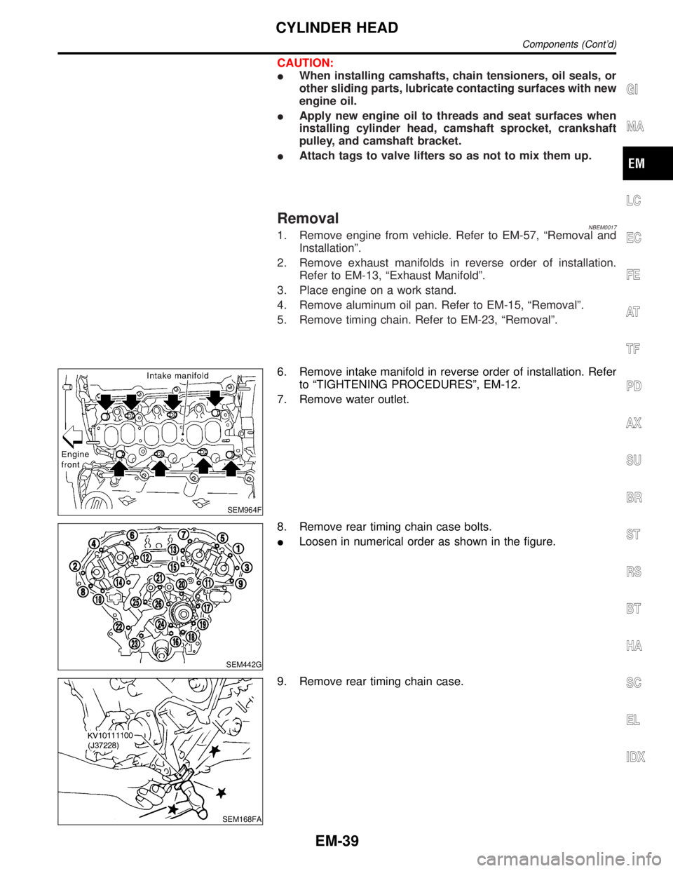
SEM964F
6. Remove intake manifold in reverse order of installation. Refer
to ªTIGHTENING PROCEDURESº, EM-12.
7. Remove water outlet.
SEM442G
8. Remove rear timing chain case bolts.
ILoosen in numerical order as shown in the figure.
SEM168FA
9. Remove rear timing chain case.
GI
MA
LC
EC
FE
AT
TF
PD
AX
SU
BR
ST
RS
BT
HA
SC
EL
IDX
CYLINDER HEAD
Components (Cont'd)
EM-39
Page 1684 of 2395

SEM444G
14. Remove RH and LH camshaft chain tensioners from cylinder
head.
SEM859E
SEM860E
15. Remove cylinder head bolts.
ICylinder head bolts should be loosened in two or three
steps.
IA warped or cracked cylinder head could result from
removing in incorrect order.
SEM863E
16. Remove cylinder head.
DisassemblyNBEM0043Remove valve component parts.
Refer to EM-35, ªVALVE OIL SEALº.
ICheck the clearance before removing the valve guide. Refer to
EM-43, ªVALVE GUIDE CLEARANCEº.
GI
MA
LC
EC
FE
AT
TF
PD
AX
SU
BR
ST
RS
BT
HA
SC
EL
IDX
CYLINDER HEAD
Removal (Cont'd)
EM-41
Page 1692 of 2395

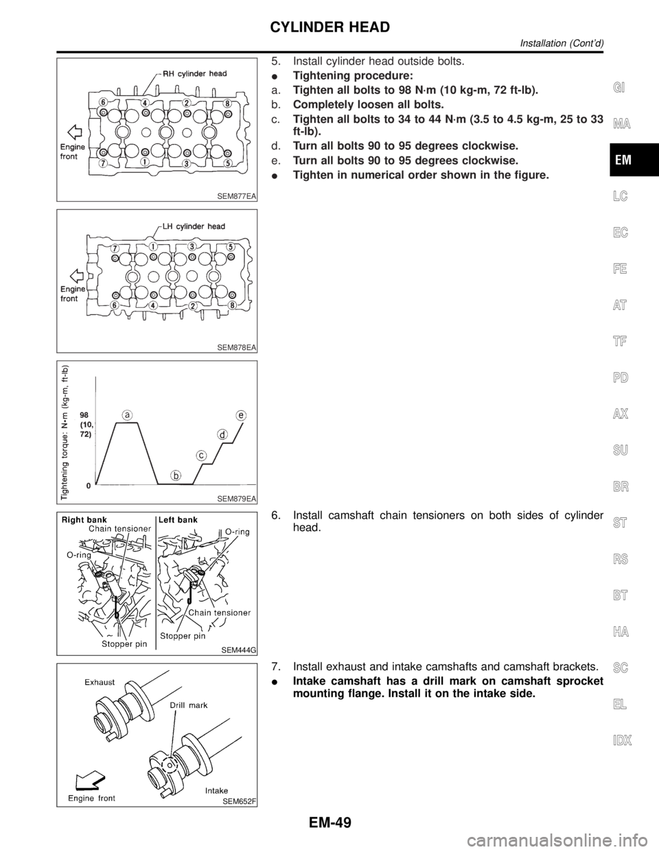
SEM877EA
SEM878EA
SEM879EA
5. Install cylinder head outside bolts.
ITightening procedure:
a.Tighten all bolts to 98 N´m (10 kg-m, 72 ft-lb).
b.Completely loosen all bolts.
c.Tighten all bolts to 34 to 44 N´m (3.5 to 4.5 kg-m, 25 to 33
ft-lb).
d.Turn all bolts 90 to 95 degrees clockwise.
e.Turn all bolts 90 to 95 degrees clockwise.
ITighten in numerical order shown in the figure.
SEM444G
6. Install camshaft chain tensioners on both sides of cylinder
head.
SEM652F
7. Install exhaust and intake camshafts and camshaft brackets.
IIntake camshaft has a drill mark on camshaft sprocket
mounting flange. Install it on the intake side.
GI
MA
LC
EC
FE
AT
TF
PD
AX
SU
BR
ST
RS
BT
HA
SC
EL
IDX
CYLINDER HEAD
Installation (Cont'd)
EM-49
Page 1746 of 2395

GENERAL INFORMATION
SECTION
GI
CONTENTS
PRECAUTIONS...............................................................3
Precautions ..................................................................3
PRECAUTIONS FOR SUPPLEMENTAL
RESTRAINT SYSTEM (SRS)²AIR BAG²AND
²SEAT BELT PRE-TENSIONER²
.................................3
PRECAUTIONS FOR IVIS (INFINITI VEHICLE
IMMOBILIZER SYSTEM - NATS)
.................................3
PRECAUTIONS FOR INFINITI COMMUNICATOR
(IVCS)
.......................................................................4
GENERAL PRECAUTIONS.........................................5
PRECAUTIONS FOR MULTIPORT FUEL
INJECTION SYSTEM OR ENGINE CONTROL
SYSTEM
...................................................................6
PRECAUTIONS FOR THREE WAY CATALYST...........6
PRECAUTIONS FOR HOSES.....................................7
PRECAUTIONS FOR ENGINE OILS...........................8
PRECAUTIONS FOR FUEL........................................8
PRECAUTIONS FOR AIR CONDITIONING..................8
HOW TO USE THIS MANUAL........................................9
HOW TO READ WIRING DIAGRAMS.......................... 11
Sample/Wiring Diagram - EXAMPL - ........................ 11
OPTIONAL SPLICE..................................................12
Description .................................................................13
CONNECTOR SYMBOLS.........................................15
HARNESS INDICATION...........................................16
COMPONENT INDICATION......................................16
SWITCH POSITIONS...............................................16
DETECTABLE LINES AND NON-DETECTABLE
LINES
.....................................................................17
MULTIPLE SWITCH.................................................18
REFERENCE AREA.................................................19
HOW TO CHECK TERMINAL.......................................21
Connector and Terminal Pin Kit.................................21
How to Probe Connectors .........................................21
PROBING FROM HARNESS SIDE............................21
PROBING FROM TERMINAL SIDE...........................21
How to Check Enlarged Contact Spring of
Terminal .....................................................................22
Waterproof Connector Inspection ..............................23
RUBBER SEAL INSPECTION...................................23
WIRE SEAL INSPECTION........................................23Terminal Lock Inspection ...........................................23
HOW TO PERFORM EFFICIENT DIAGNOSIS
FOR AN ELECTRICAL INCIDENT...............................24
Work Flow ..................................................................24
Incident Simulation Tests ...........................................25
INTRODUCTION......................................................25
VEHICLE VIBRATION..............................................25
HEAT SENSITIVE....................................................26
FREEZING..............................................................26
WATER INTRUSION................................................27
ELECTRICAL LOAD.................................................27
COLD OR HOT START UP.......................................27
Circuit Inspection .......................................................27
INTRODUCTION......................................................27
TESTING FOR²OPENS²IN THE CIRCUIT................28
TESTING FOR²SHORTS²IN THE CIRCUIT..............29
GROUND INSPECTION...........................................30
VOLTAGE DROP TESTS..........................................30
CONTROL UNIT CIRCUIT TEST...............................32
HOW TO FOLLOW TROUBLE DIAGNOSIS................34
How to Follow Test Groups in Trouble Diagnosis .....35
Key to Symbols Signifying Measurements or
Procedures.................................................................36
CONSULT-II CHECKING SYSTEM...............................38
Function and System Application ..............................38
Nickel Metal Hydride Battery Replacement...............39
Checking Equipment..................................................39
CONSULT-II Data Link Connector (DLC) Circuit ......40
INSPECTION PROCEDURE.....................................40
IDENTIFICATION INFORMATION................................41
Model Variation ..........................................................41
PREFIX AND SUFFIX DESIGNATIONS.....................41
Identification Number .................................................41
VEHICLE IDENTIFICATION NUMBER
ARRANGEMENT
.....................................................42
IDENTIFICATION PLATE..........................................42
ENGINE SERIAL NUMBER.......................................43
AUTOMATIC TRANSMISSION NUMBER...................43
TRANSFER SERIAL NUMBER..................................43
Dimensions ................................................................43
MA
EM
LC
EC
FE
AT
TF
PD
AX
SU
BR
ST
RS
BT
HA
SC
EL
IDX
Page 1748 of 2395

PrecautionsNBGI0001Observe the following precautions to ensure safe and proper
servicing. These precautions are not described in each indi-
vidual section.
SGI646
PRECAUTIONS FOR SUPPLEMENTAL RESTRAINT
SYSTEM (SRS) ªAIR BAGº AND ªSEAT BELT
PRE-TENSIONERº
NBGI0001S01The Supplemental Restraint System such as ªAIR BAGº and ªSEAT
BELT PRE-TENSIONERº used along with a seat belt, helps to
reduce the risk or severity of injury to the driver and front passen-
ger for certain types of collision. The SRS system composition
which is available to INFINITI QX4 is as follows:
IFor a frontal collision
The Supplemental Restraint System consists of driver air bag
module (located in the center of the steering wheel), front pas-
senger air bag module (located on the instrument panel on
passenger side), seat belt pre-tensioners, a diagnosis sensor
unit, warning lamp, wiring harness and spiral cable.
IFor a side collision
The Supplemental Restraint System consists of side air bag
module (located in the outer side of front seat), satellite sensor,
diagnosis sensor unit (one of components of air bags for a
frontal collision), wiring harness, warning lamp (one of compo-
nents of air bags for a frontal collision).
Information necessary to service the system safely is included in
theRS sectionof this Service Manual.
WARNING:
ITo avoid rendering the SRS inoperative, which could
increase the risk of personal injury or death in the event
of a collision which would result in air bag inflation, all
maintenance must be performed by an authorized INFINITI
dealer.
IImproper maintenance, including incorrect removal and
installation of the SRS, can lead to personal injury caused
by unintentional activation of the system. For removal of
Spiral Cable and Air Bag Module, see the RS section.
IDo not use electrical test equipment on any circuit related
to the SRS unless instructed to in this Service Manual.
Spiral cable and wiring harnesses covered with yellow
insulation tape either just before the harness connectors
or for the complete harness are related to the SRS.
PRECAUTIONS FOR IVIS (INFINITI VEHICLE
IMMOBILIZER SYSTEM Ð NATS)
NBGI0001S08IVIS (NATS) will immobilize the engine if someone tries to start it
without the registered key of IVIS (NATS).
Both of the originally supplied ignition key IDs have been IVIS
(NATS) registered.
MA
EM
LC
EC
FE
AT
TF
PD
AX
SU
BR
ST
RS
BT
HA
SC
EL
IDX
PRECAUTIONS
Precautions
GI-3
Page 1800 of 2395

HEATER &
AIR CONDITIONER
SECTION
HA
CONTENTS
PRECAUTIONS...............................................................2
Supplemental Restraint System (SRS)²AIR
BAG²and²SEAT BELT PRE-TENSIONER²...............2
Precautions for Working with HFC-134a (R-134a) .....2
General Refrigerant Precautions .................................3
Precautions for Leak Detection Dye............................3
Identification .................................................................4
Precautions for Refrigerant Connection ......................4
Precautions for Servicing Compressor ........................6
Precautions for Service Equipment .............................7
Wiring Diagrams and Trouble Diagnoses....................9
PREPARATION.............................................................10
Special Service Tools ................................................10
HFC-134a (R-134a) Service Tools and
Equipment .................................................................. 11
DESCRIPTION...............................................................14
Refrigeration System .................................................14
V-6 Variable Displacement Compressor....................15
Component Layout ....................................................19
Introduction ................................................................20
Features .....................................................................20
Overview of Control System ......................................23
Control Operation ......................................................23
Discharge Air Flow.....................................................25
System Description ....................................................26
TROUBLE DIAGNOSES................................................27
Component Location..................................................27
Circuit Diagram (Without Navigation System) ...........30
Wiring Diagram - A/C, A - (Without Navigation
System) ......................................................................31
Circuit Diagram (With Navigation System) ................35
Wiring Diagram - A/C, A - (With Navigation
System) ......................................................................36
Auto Amp. Terminals and Reference Value...............40
Self-diagnosis ............................................................44
How to Perform Trouble Diagnoses for Quick
and Accurate Repair ..................................................65Operational Check .....................................................66
A/C System ................................................................71
Mode Door Motor.......................................................75
Air Mix Door Motor ....................................................82
Intake Door Motor ......................................................87
Blower Motor..............................................................95
Magnet Clutch..........................................................104
Insufficient Cooling .................................................. 112
Insufficient Heating ..................................................121
Noise ........................................................................123
Self-diagnosis ..........................................................124
Memory Function .....................................................126
ECON (ECONOMY) Mode ......................................128
Ambient Sensor Circuit ............................................129
In-vehicle Sensor Circuit..........................................132
Sunload Sensor Circuit ............................................135
Intake Sensor Circuit ...............................................139
Air Mix Door Motor PBR Circuit ..............................141
Multiplex Communication Circuit .............................142
SERVICE PROCEDURE..............................................144
HFC-134a (R-134a) Service Procedure ..................144
Maintenance of Lubricant Quantity in
Compressor .............................................................146
Compressor .............................................................149
Compressor Clutch ..................................................150
Refrigerant Lines .....................................................154
Belt ...........................................................................159
Ventilation Air Filter ..................................................159
SERVICE DATA AND SPECIFICATIONS (SDS).......160
Compressor .............................................................160
Lubricant ..................................................................160
Refrigerant ...............................................................160
Engine Idling Speed (When A/C is ON) ..................160
Belt Tension .............................................................160
GI
MA
EM
LC
EC
FE
AT
TF
PD
AX
SU
BR
ST
RS
BT
SC
EL
IDX