Page 2163 of 2395
Trouble Diagnoses with
Battery/Starting/Charging System Tester
NBSC0019NOTE:
To ensure a complete and thorough diagnosis, the battery, starter
and alternator test segments must be done as a set from start to
finish.
SEL408X
1. Turn off all loads on the vehicle electrical system.
2. Perform battery test with Battery/Starting/Charging system
tester. Refer to SC-7.
3. Press ªENTERº to begin the starting system test.
SEL409X
4. Start the engine.
SEL410X
5. Diagnosis result is displayed on the tester. Refer to ªDIAG-
NOSTIC RESULT ITEM CHARTº, SC-13.
NOTE:
IIf the starter performs normally but the engine does not start,
perform engine diagnosis.
IFor intermittent ªNO CRANKº or ªNO STARTER OPERATIONº
incidents, go to DIAGNOSTIC PROCEDURE 2.
STARTING SYSTEM
Trouble Diagnoses with Battery/Starting/Charging System Tester
SC-12
Page 2166 of 2395
DIAGNOSTIC PROCEDURE 1NBSC0019S03Check ªBº Terminal CircuitNBSC0019S0301
1 CHECK POWER SUPPLY FOR STARTER MOTOR ªBº TERMINAL
1. Remove the fuel pump fuse.
2. Crank or start the engine (where possible) until the fuel pressure is released.
3. Turn the ignition OFF.
4. Check that the starter motor terminal 1 connection is clean and tight.
5. Check voltage between starter motor terminal 1 and ground using a digital circuit tester.
SEL412X
OK or NG
OK©GO TO 2.
NG©Check harness between the battery and the starter motor for open circuit.
2 CHECK BATTERY CABLE CONNECTION QUALITY (VOLTAGE DROP TEST)
1. Check voltage between starter motor terminal 1 and battery positive terminal using a digital circuit tester.
SEL413X
OK or NG
OK©GO TO 3.
NG©Check harness between the battery and the starter motor for poor continuity.
GI
MA
EM
LC
EC
FE
AT
TF
PD
AX
SU
BR
ST
RS
BT
HA
EL
IDX
STARTING SYSTEM
Trouble Diagnoses with Battery/Starting/Charging System Tester (Cont'd)
SC-15
Page 2167 of 2395
3 CHECK STARTER MOTOR GROUND CIRCUIT (VOLTAGE DROP TEST)
1. Check voltage between starter motor case and battery negative terminal using a digital circuit tester.
SEL414X
OK or NG
OK©Starter motor ªBº terminal circuit is OK. Further inspection necessary. Refer to ªWORK
FLOWº, SC-14.
NG©Check the starter motor case and ground for poor continuity.
STARTING SYSTEM
Trouble Diagnoses with Battery/Starting/Charging System Tester (Cont'd)
SC-16
Page 2168 of 2395

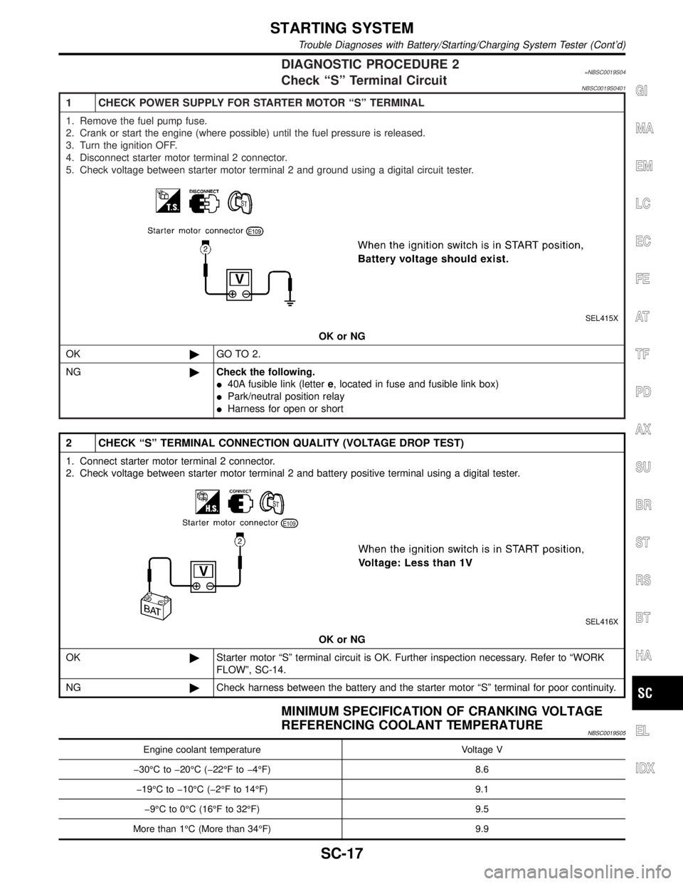
DIAGNOSTIC PROCEDURE 2=NBSC0019S04Check ªSº Terminal CircuitNBSC0019S0401
1 CHECK POWER SUPPLY FOR STARTER MOTOR ªSº TERMINAL
1. Remove the fuel pump fuse.
2. Crank or start the engine (where possible) until the fuel pressure is released.
3. Turn the ignition OFF.
4. Disconnect starter motor terminal 2 connector.
5. Check voltage between starter motor terminal 2 and ground using a digital circuit tester.
SEL415X
OK or NG
OK©GO TO 2.
NG©Check the following.
I40A fusible link (lettere, located in fuse and fusible link box)
IPark/neutral position relay
IHarness for open or short
2 CHECK ªSº TERMINAL CONNECTION QUALITY (VOLTAGE DROP TEST)
1. Connect starter motor terminal 2 connector.
2. Check voltage between starter motor terminal 2 and battery positive terminal using a digital tester.
SEL416X
OK or NG
OK©Starter motor ªSº terminal circuit is OK. Further inspection necessary. Refer to ªWORK
FLOWº, SC-14.
NG©Check harness between the battery and the starter motor ªSº terminal for poor continuity.
MINIMUM SPECIFICATION OF CRANKING VOLTAGE
REFERENCING COOLANT TEMPERATURE
NBSC0019S05
Engine coolant temperature Voltage V
þ30ÉC to þ20ÉC (þ22ÉF to þ4ÉF) 8.6
þ19ÉC to þ10ÉC (þ2ÉF to 14ÉF) 9.1
þ9ÉC to 0ÉC (16ÉF to 32ÉF) 9.5
More than 1ÉC (More than 34ÉF) 9.9
GI
MA
EM
LC
EC
FE
AT
TF
PD
AX
SU
BR
ST
RS
BT
HA
EL
IDX
STARTING SYSTEM
Trouble Diagnoses with Battery/Starting/Charging System Tester (Cont'd)
SC-17
Page 2172 of 2395

Trouble Diagnoses with
Battery/Starting/Charging System Tester
NBSC0020NOTE:
To ensure a complete and thorough diagnosis, the battery, starter
and alternator test segments must be done as a set from start to
finish.
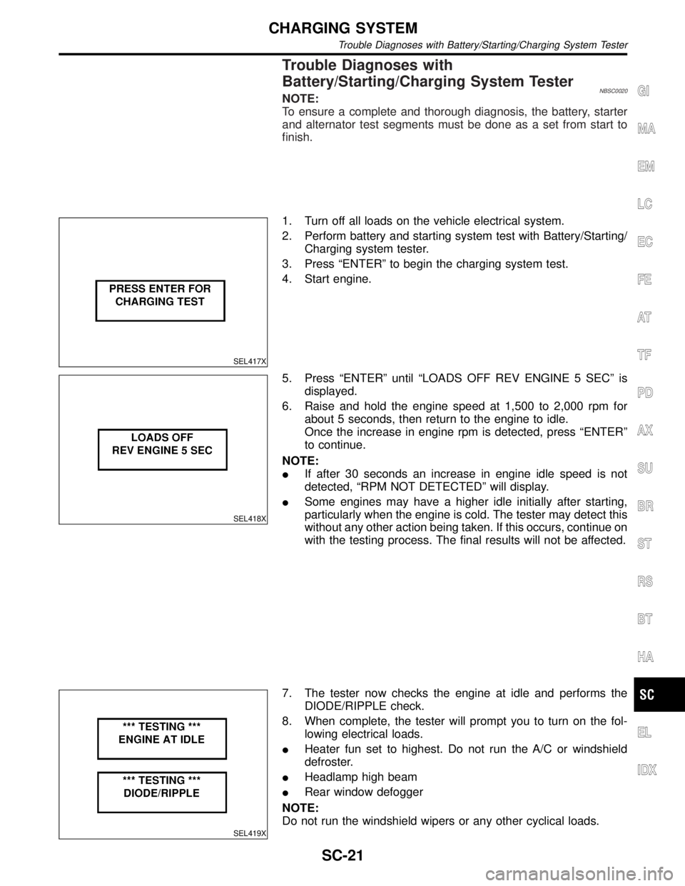
SEL417X
1. Turn off all loads on the vehicle electrical system.
2. Perform battery and starting system test with Battery/Starting/
Charging system tester.
3. Press ªENTERº to begin the charging system test.
4. Start engine.
SEL418X
5. Press ªENTERº until ªLOADS OFF REV ENGINE 5 SECº is
displayed.
6. Raise and hold the engine speed at 1,500 to 2,000 rpm for
about 5 seconds, then return to the engine to idle.
Once the increase in engine rpm is detected, press ªENTERº
to continue.
NOTE:
IIf after 30 seconds an increase in engine idle speed is not
detected, ªRPM NOT DETECTEDº will display.
ISome engines may have a higher idle initially after starting,
particularly when the engine is cold. The tester may detect this
without any other action being taken. If this occurs, continue on
with the testing process. The final results will not be affected.
SEL419X
7. The tester now checks the engine at idle and performs the
DIODE/RIPPLE check.
8. When complete, the tester will prompt you to turn on the fol-
lowing electrical loads.
IHeater fun set to highest. Do not run the A/C or windshield
defroster.
IHeadlamp high beam
IRear window defogger
NOTE:
Do not run the windshield wipers or any other cyclical loads.
GI
MA
EM
LC
EC
FE
AT
TF
PD
AX
SU
BR
ST
RS
BT
HA
EL
IDX
CHARGING SYSTEM
Trouble Diagnoses with Battery/Starting/Charging System Tester
SC-21
Page 2180 of 2395

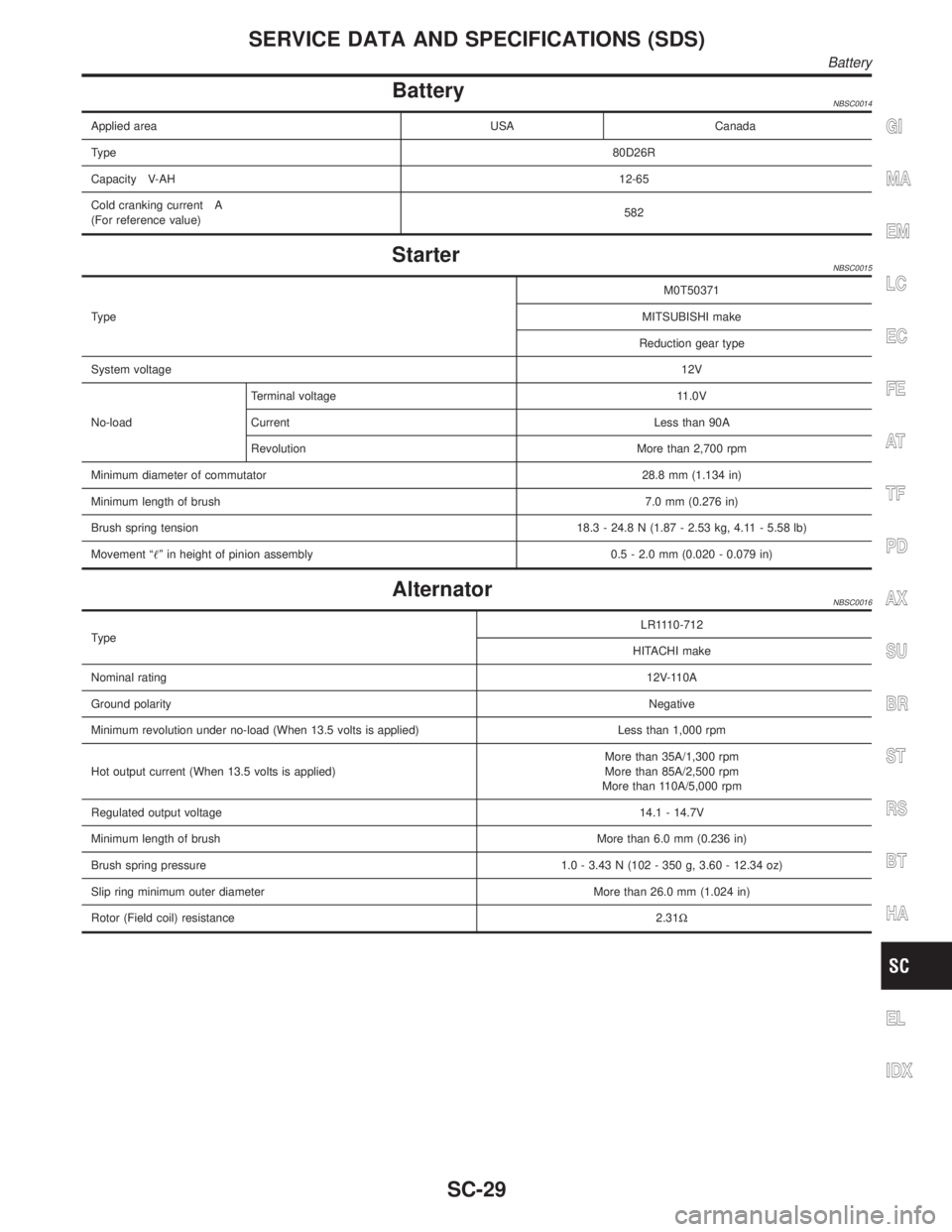
BatteryNBSC0014
Applied area USA Canada
Type80D26R
Capacity V-AH12-65
Cold cranking current A
(For reference value)582
StarterNBSC0015
TypeM0T50371
MITSUBISHI make
Reduction gear type
System voltage12V
No-loadTerminal voltage 11.0V
Current Less than 90A
Revolution More than 2,700 rpm
Minimum diameter of commutator28.8 mm (1.134 in)
Minimum length of brush7.0 mm (0.276 in)
Brush spring tension18.3 - 24.8 N (1.87 - 2.53 kg, 4.11 - 5.58 lb)
Movement ªº in height of pinion assembly 0.5 - 2.0 mm (0.020 - 0.079 in)
AlternatorNBSC0016
TypeLR1110-712
HITACHI make
Nominal rating12V-110A
Ground polarityNegative
Minimum revolution under no-load (When 13.5 volts is applied) Less than 1,000 rpm
Hot output current (When 13.5 volts is applied)More than 35A/1,300 rpm
More than 85A/2,500 rpm
More than 110A/5,000 rpm
Regulated output voltage14.1 - 14.7V
Minimum length of brushMore than 6.0 mm (0.236 in)
Brush spring pressure 1.0 - 3.43 N (102 - 350 g, 3.60 - 12.34 oz)
Slip ring minimum outer diameter More than 26.0 mm (1.024 in)
Rotor (Field coil) resistance2.31W
GI
MA
EM
LC
EC
FE
AT
TF
PD
AX
SU
BR
ST
RS
BT
HA
EL
IDX
SERVICE DATA AND SPECIFICATIONS (SDS)
Battery
SC-29
Page:
< prev 1-8 9-16 17-24