2001 INFINITI QX4 maintenance
[x] Cancel search: maintenancePage 1806 of 2395
Precautions for Service EquipmentNBHA0006RECOVERY/RECYCLING EQUIPMENTNBHA0006S01Be certain to follow the manufacturers instructions for machine
operation and machine maintenance. Never introduce any refriger-
ant other than that specified into the machine.
ELECTRONIC LEAK DETECTORNBHA0006S02Be certain to follow the manufacturer's instructions for tester opera-
tion and tester maintenance.
RHA270DA
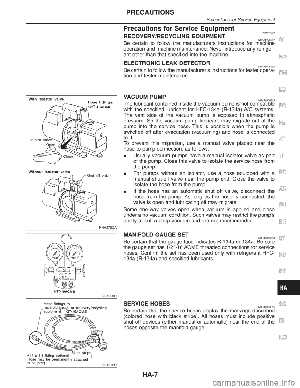
VACUUM PUMPNBHA0006S03The lubricant contained inside the vacuum pump is not compatible
with the specified lubricant for HFC-134a (R-134a) A/C systems.
The vent side of the vacuum pump is exposed to atmospheric
pressure. So the vacuum pump lubricant may migrate out of the
pump into the service hose. This is possible when the pump is
switched off after evacuation (vacuuming) and hose is connected
to it.
To prevent this migration, use a manual valve placed near the
hose-to-pump connection, as follows.
IUsually vacuum pumps have a manual isolator valve as part
of the pump. Close this valve to isolate the service hose from
the pump.
IFor pumps without an isolator, use a hose equipped with a
manual shut-off valve near the pump end. Close the valve to
isolate the hose from the pump.
IIf the hose has an automatic shut off valve, disconnect the
hose from the pump. As long as the hose is connected, the
valve is open and lubricating oil may migrate.
Some one-way valves open when vacuum is applied and close
under a no vacuum condition. Such valves may restrict the pump's
ability to pull a deep vacuum and are not recommended.
SHA533D
MANIFOLD GAUGE SETNBHA0006S04Be certain that the gauge face indicates R-134a or 134a. Be sure
the gauge set has 1/2²-16 ACME threaded connections for service
hoses. Confirm the set has been used only with refrigerant HFC-
134a (R-134a) and specified lubricants.
RHA272D
SERVICE HOSESNBHA0006S05Be certain that the service hoses display the markings described
(colored hose with black stripe). All hoses must include positive
shut off devices (either manual or automatic) near the end of the
hoses opposite the manifold gauge.
GI
MA
EM
LC
EC
FE
AT
TF
PD
AX
SU
BR
ST
RS
BT
SC
EL
IDX
PRECAUTIONS
Precautions for Service Equipment
HA-7
Page 1945 of 2395
Maintenance of Lubricant Quantity in
Compressor
NBHA0071The lubricant in the compressor circulates through the system with
the refrigerant. Add lubricant to compressor when replacing any
component or after a large gas leakage occurred. It is important to
maintain the specified amount.
If lubricant quantity is not maintained properly, the following mal-
functions may result:
ILack of lubricant: May lead to a seized compressor
IExcessive lubricant: Inadequate cooling (thermal exchange
interference)
LUBRICANTNBHA0071S01Name: Nissan A/C System Oil Type S
Part number: KLH00-PAGS0
CHECKING AND ADJUSTINGNBHA0071S02Adjust the lubricant quantity according to the test group shown
below.
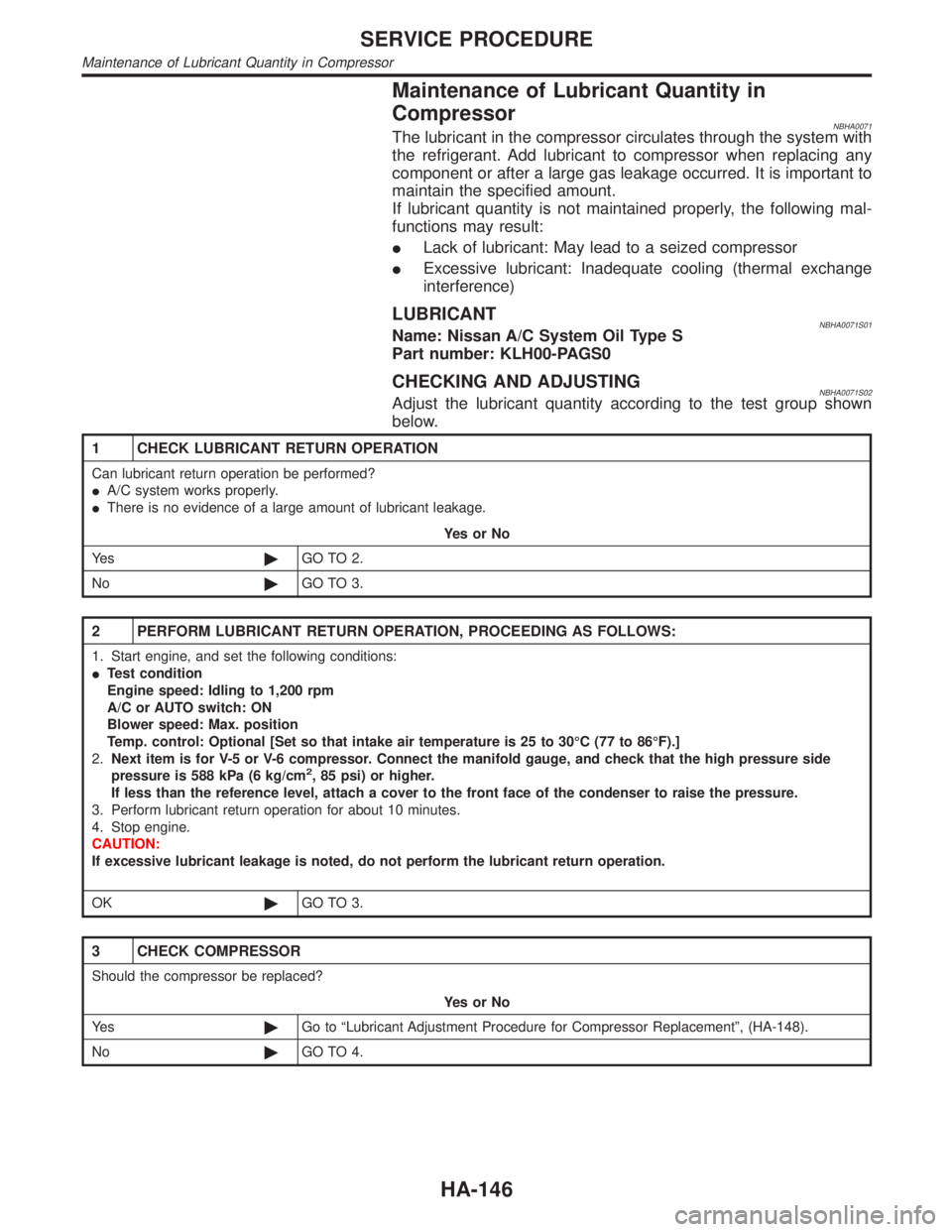
1 CHECK LUBRICANT RETURN OPERATION
Can lubricant return operation be performed?
IA/C system works properly.
IThere is no evidence of a large amount of lubricant leakage.
YesorNo
Ye s©GO TO 2.
No©GO TO 3.
2 PERFORM LUBRICANT RETURN OPERATION, PROCEEDING AS FOLLOWS:
1. Start engine, and set the following conditions:
ITest condition
Engine speed: Idling to 1,200 rpm
A/C or AUTO switch: ON
Blower speed: Max. position
Temp. control: Optional [Set so that intake air temperature is 25 to 30ÉC (77 to 86ÉF).]
2.Next item is for V-5 or V-6 compressor. Connect the manifold gauge, and check that the high pressure side
pressure is 588 kPa (6 kg/cm
2, 85 psi) or higher.
If less than the reference level, attach a cover to the front face of the condenser to raise the pressure.
3. Perform lubricant return operation for about 10 minutes.
4. Stop engine.
CAUTION:
If excessive lubricant leakage is noted, do not perform the lubricant return operation.
OK©GO TO 3.
3 CHECK COMPRESSOR
Should the compressor be replaced?
YesorNo
Ye s©Go to ªLubricant Adjustment Procedure for Compressor Replacementº, (HA-148).
No©GO TO 4.
SERVICE PROCEDURE
Maintenance of Lubricant Quantity in Compressor
HA-146
Page 1946 of 2395
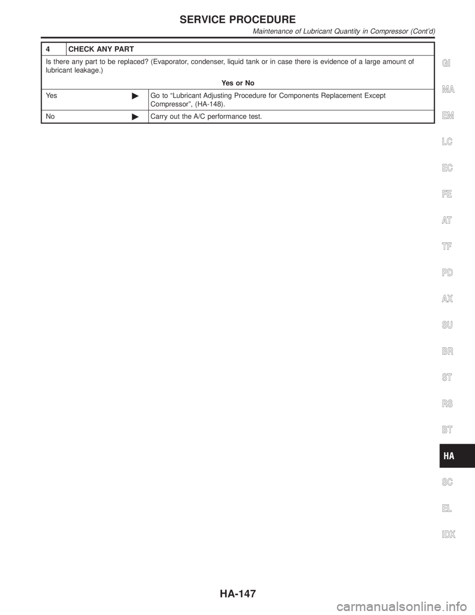
4 CHECK ANY PART
Is there any part to be replaced? (Evaporator, condenser, liquid tank or in case there is evidence of a large amount of
lubricant leakage.)
YesorNo
Ye s©Go to ªLubricant Adjusting Procedure for Components Replacement Except
Compressorº, (HA-148).
No©Carry out the A/C performance test.GI
MA
EM
LC
EC
FE
AT
TF
PD
AX
SU
BR
ST
RS
BT
SC
EL
IDX
SERVICE PROCEDURE
Maintenance of Lubricant Quantity in Compressor (Cont'd)
HA-147
Page 1947 of 2395
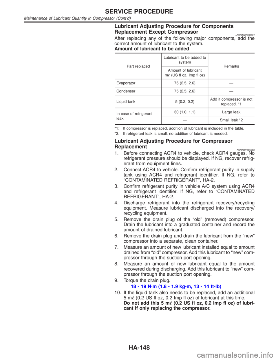
Lubricant Adjusting Procedure for Components
Replacement Except Compressor
=NBHA0071S0201After replacing any of the following major components, add the
correct amount of lubricant to the system.
Amount of lubricant to be added
Part replacedLubricant to be added to
system
Remarks
Amount of lubricant
m(US fl oz, Imp fl oz)
Evaporator 75 (2.5, 2.6) Ð
Condenser 75 (2.5, 2.6) Ð
Liquid tank 5 (0.2, 0.2)Add if compressor is not
replaced. *1
In case of refrigerant
leak30 (1.0, 1.1) Large leak
Ð Small leak *2
*1: If compressor is replaced, addition of lubricant is included in the table.
*2: If refrigerant leak is small, no addition of lubricant is needed.
Lubricant Adjusting Procedure for Compressor
Replacement
NBHA0071S02021. Before connecting ACR4 to vehicle, check ACR4 gauges. No
refrigerant pressure should be displayed. If NG, recover refrig-
erant from equipment lines.
2. Connect ACR4 to vehicle. Confirm refrigerant purity in supply
tank using ACR4 and refrigerant identifier. If NG, refer to
ªCONTAMINATED REFRIGERANTº, HA-2.
3. Confirm refrigerant purity in vehicle A/C system using ACR4
and refrigerant identifier. If NG, refer to ªCONTAMINATED
REFRIGERANTº, HA-2.
4. Discharge refrigerant into the refrigerant recovery/recycling
equipment. Measure lubricant discharged into the recovery/
recycling equipment.
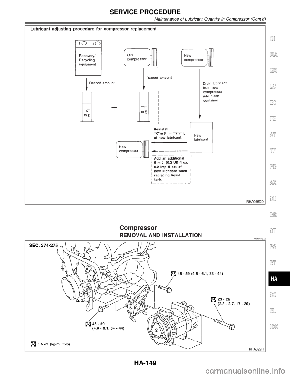
5. Remove the drain plug of the ªoldº (removed) compressor.
Drain the lubricant into a graduated container and record the
amount of drained lubricant.
6. Remove the drain plug and drain the lubricant from the ªnewº
compressor into a separate, clean container.
7. Measure an amount of new lubricant installed equal to amount
drained from ªoldº compressor. Add this lubricant to ªnewº com-
pressor through the suction port opening.
8. Measure an amount of new lubricant equal to the amount
recovered during discharging. Add this lubricant to ªnewº com-
pressor through the suction port opening.
9. Torque the drain plug.
18 - 19 N´m (1.8 - 1.9 kg-m, 13 - 14 ft-lb)
10. If the liquid tank also needs to be replaced, add an additional
5m(0.2 US fl oz, 0.2 Imp fl oz) of lubricant at this time.
Do not add this 5 m(0.2 US fl oz, 0.2 Imp fl oz) of lubri-
cant if only replacing the compressor.
SERVICE PROCEDURE
Maintenance of Lubricant Quantity in Compressor (Cont'd)
HA-148
Page 1948 of 2395
RHA065DD
Compressor
REMOVAL AND INSTALLATIONNBHA0072
RHA892H
GI
MA
EM
LC
EC
FE
AT
TF
PD
AX
SU
BR
ST
RS
BT
SC
EL
IDX
SERVICE PROCEDURE
Maintenance of Lubricant Quantity in Compressor (Cont'd)
HA-149
Page 1955 of 2395
5. When the A/C operating (compressor running), inject one
bottle (1/4 ounce /7.4 cc) of fluorescent dye through the low-
pressure service valve using dye injector tool J-41459 (refer to
the manufacture's operating instructions).
6. With the engine still running, disconnect the injector tool from
the service fitting.
CAUTION:
Be careful not to allow dye to spray or drip when disconnect-
ing the injector from the system.
NOTE:
If repairing the A/C system or replacing a component, pour the
dye directly into the open system connection and proceed
with the service procedures.
7. Operate the A/C system for a minimum of 20 minutes to mix
the dye with the system oil. Depending on the leak size, oper-
ating conditions and location of the leak, it may take from min-
utes to days for the dye to penetrate a leak and become visible.
SHA196FA
ELECTRONIC REFRIGERANT LEAK DETECTORNBHA0115Precautions for Handling Leak DetectorNBHA0115S01When performing a refrigerant leak check, use a J-41995 A/C leak
detector or equivalent. Ensure that the instrument is calibrated and
set properly per the operating instructions.
The leak detector is a delicate device. In order to use the leak
detector properly, read the operating instructions and perform any
specified maintenance.
SHA707EA
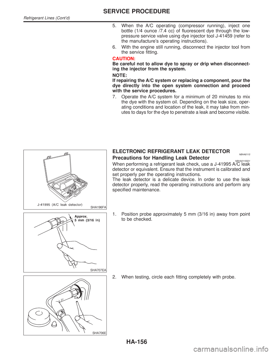
1. Position probe approximately 5 mm (3/16 in) away from point
to be checked.
SHA706E
2. When testing, circle each fitting completely with probe.
SERVICE PROCEDURE
Refrigerant Lines (Cont'd)
HA-156
Page 1959 of 2395
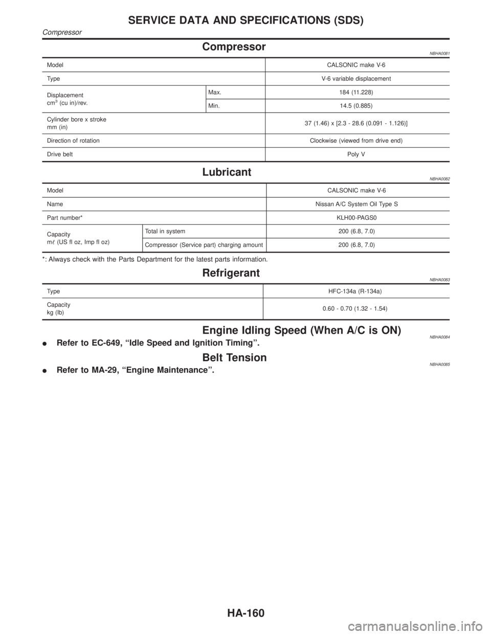
CompressorNBHA0081
ModelCALSONIC make V-6
TypeV-6 variable displacement
Displacement
cm
3(cu in)/rev.Max. 184 (11.228)
Min. 14.5 (0.885)
Cylinder bore x stroke
mm (in)37 (1.46) x [2.3 - 28.6 (0.091 - 1.126)]
Direction of rotationClockwise (viewed from drive end)
Drive beltPoly V
LubricantNBHA0082
ModelCALSONIC make V-6
NameNissan A/C System Oil Type S
Part number*KLH00-PAGS0
Capacity
m(US fl oz, Imp fl oz)Total in system 200 (6.8, 7.0)
Compressor (Service part) charging amount 200 (6.8, 7.0)
*: Always check with the Parts Department for the latest parts information.
RefrigerantNBHA0083
TypeHFC-134a (R-134a)
Capacity
kg (lb)0.60 - 0.70 (1.32 - 1.54)
Engine Idling Speed (When A/C is ON)NBHA0084IRefer to EC-649, ªIdle Speed and Ignition Timingº.
Belt TensionNBHA0085IRefer to MA-29, ªEngine Maintenanceº.
SERVICE DATA AND SPECIFICATIONS (SDS)
Compressor
HA-160
Page 1962 of 2395
Brake fluid change ...........................................BR-7
Brake fluid level .............................................MA-25
Brake fluid level and line check .......................BR-7
Brake hydraulic line ..........................................BR-9
Brake inspection ............................................MA-25
Brake lines and cables inspection .................MA-25
Brake lining wear temporary checking ..........MA-26
Brake master cylinder ....................................BR-16
Brake pedal ....................................................BR-14
Bulb specifications ........................................EL-456
Bumper, front ..................................................BT-12
Bumper, rear ...................................................BT-15
BYPS/V - Wiring diagram ....................EC-587, 594
C
Camshaft inspection ......................................EM-42
Camshaft position sensor (PHASE) .............EC-342
Canister-See EVAP canister ..........................EC-32
Center bearing assembly (propeller
shaft) .............................................................PD-9
Center bearing disassembly (propeller
shaft) .............................................................PD-7
Center case (Transfer) ..................................TF-123
CHARGE - Wiring diagram ............................SC-20
Charging system ............................................SC-19
Chassis and body maintenance ....................MA-21
CHIME - Wiring diagram...............................EL-127
CIGAR - Wiring diagram ...............................EL-148
Cigarette lighter.............................................EL-148
Circuit breaker.................................................EL-16
CKPS - Wiring diagram ................................EC-334
Closed loop control (Left bank) ....................EC-491
Closed loop control (Right bank) .................EC-491
Closed throttle position switch .....................EC-431
Clutch drum (Transfer) ..................................TF-125
Clutch force release limit adjustment .............TF-39
Clutch pressure switch (Transfer) .................TF-111
Coil spring (front)..............................................SU-8
Coil spring (rear) ............................................SU-18
Collision diagnosis..........................................RS-59
Combination lamp, front, removal and
installation ...................................................BT-12
Combination lamp, rear, removal and
installation ...................................................BT-35
Combination meter..........................................EL-94
Combination meter removal and instal-
lation - See Instrument panel ......................BT-21
Combination switch .........................................EL-28
COMPAS - Wiring diagram ...........................EL-111
Compass .......................................................EL-110
Component Location (auto A/C).....................HA-27
Compression pressure ...................................EM-14
Compressor clutch removal and
installation .................................................HA-150
Compressor precaution ....................................HA-6
Compressor special service tool ....................HA-10
Connecting rod...............................................EM-65
Connecting rod bearing clearance.................EM-69
Connecting rod bushing clearance ................EM-70Connector inspection .......................................GI-21
Console box - See Instrument panel ..............BT-21
CONSULT for ABS .........................................BR-43
CONSULT for all-mode 4WD ..........................TF-30
CONSULT for engine .....................................EC-81
CONSULT-II general information .....................GI-38
Control valve (A/T) ........................................AT-301
Control valve (Transfer) ................................TF-128
Converter housing installation .......................AT-278
Coolant mixture ratio......................................MA-12
Coolant replacement ......................................MA-14
Cooling circuit (engine) ...................................LC-10
``Crankcase emission control system -
See positive crankcase ventilation''............EC-38
Crankshaft ......................................................EM-67
Crankshaft position sensor (POS) ...............EC-334
Crankshaft position sensor (POS)
chipping ....................................................EC-517
Crankshaft position sensor (REF) ................EC-510
Cruise control - See ASCD ...........................EL-221
Cylinder block ................................................EM-61
Cylinder head .................................................EM-38
Cylinder head bolt tightening .........................EM-49
D
Data link connector for Consult......................EC-81
Daytime light system.......................................EL-46
Daytime running light - See Daytime
light system .................................................EL-46
DEF - Wiring diagram ...................................EL-153
Detonation sensor - See Knock sensor .......EC-328
Diagnostic trouble code (DTC) for OBD
system ....................................................EC-8, 60
Diagnostic trouble code (DTC) inspec-
tion priority chart .......................................EC-116
Differential carrier assembly.....................PD-30, 57
Differential carrier disassembly ......................PD-44
Differential gear oil replacement ....................MA-24
Dimensions ......................................................GI-43
D/LOCK - Wiring diagram .............................EL-256
Dome light - See Interior lamp .......................EL-88
Door glass .......................................................BT-18
Door lock .........................................................BT-18
Door mirror ......................................................BT-56
Door trim .........................................................BT-30
Door, front .......................................................BT-18
Door, rear ........................................................BT-20
Drive belt inspection ......................................MA-13
Drive chain (Transfer) ...................................TF-125
Drive pinion diff. inspection ......................PD-23, 47
Drive pinion height ...................................PD-25, 53
Drive plate runout ..........................................EM-70
Drive shaft (front)............................................AX-10
Dropping resistor (A/T) ..................................AT-167
DTC work support ..........................................EC-93
DTRL - Wiring diagram ...................................EL-51
GI
MA
EM
LC
EC
FE
AT
TF
PD
AX
SU
BR
ST
RS
BT
HA
SC
EL
ALPHABETICAL INDEX
IDX-3