2001 INFINITI QX4 heating
[x] Cancel search: heatingPage 1800 of 2395

HEATER &
AIR CONDITIONER
SECTION
HA
CONTENTS
PRECAUTIONS...............................................................2
Supplemental Restraint System (SRS)²AIR
BAG²and²SEAT BELT PRE-TENSIONER²...............2
Precautions for Working with HFC-134a (R-134a) .....2
General Refrigerant Precautions .................................3
Precautions for Leak Detection Dye............................3
Identification .................................................................4
Precautions for Refrigerant Connection ......................4
Precautions for Servicing Compressor ........................6
Precautions for Service Equipment .............................7
Wiring Diagrams and Trouble Diagnoses....................9
PREPARATION.............................................................10
Special Service Tools ................................................10
HFC-134a (R-134a) Service Tools and
Equipment .................................................................. 11
DESCRIPTION...............................................................14
Refrigeration System .................................................14
V-6 Variable Displacement Compressor....................15
Component Layout ....................................................19
Introduction ................................................................20
Features .....................................................................20
Overview of Control System ......................................23
Control Operation ......................................................23
Discharge Air Flow.....................................................25
System Description ....................................................26
TROUBLE DIAGNOSES................................................27
Component Location..................................................27
Circuit Diagram (Without Navigation System) ...........30
Wiring Diagram - A/C, A - (Without Navigation
System) ......................................................................31
Circuit Diagram (With Navigation System) ................35
Wiring Diagram - A/C, A - (With Navigation
System) ......................................................................36
Auto Amp. Terminals and Reference Value...............40
Self-diagnosis ............................................................44
How to Perform Trouble Diagnoses for Quick
and Accurate Repair ..................................................65Operational Check .....................................................66
A/C System ................................................................71
Mode Door Motor.......................................................75
Air Mix Door Motor ....................................................82
Intake Door Motor ......................................................87
Blower Motor..............................................................95
Magnet Clutch..........................................................104
Insufficient Cooling .................................................. 112
Insufficient Heating ..................................................121
Noise ........................................................................123
Self-diagnosis ..........................................................124
Memory Function .....................................................126
ECON (ECONOMY) Mode ......................................128
Ambient Sensor Circuit ............................................129
In-vehicle Sensor Circuit..........................................132
Sunload Sensor Circuit ............................................135
Intake Sensor Circuit ...............................................139
Air Mix Door Motor PBR Circuit ..............................141
Multiplex Communication Circuit .............................142
SERVICE PROCEDURE..............................................144
HFC-134a (R-134a) Service Procedure ..................144
Maintenance of Lubricant Quantity in
Compressor .............................................................146
Compressor .............................................................149
Compressor Clutch ..................................................150
Refrigerant Lines .....................................................154
Belt ...........................................................................159
Ventilation Air Filter ..................................................159
SERVICE DATA AND SPECIFICATIONS (SDS).......160
Compressor .............................................................160
Lubricant ..................................................................160
Refrigerant ...............................................................160
Engine Idling Speed (When A/C is ON) ..................160
Belt Tension .............................................................160
GI
MA
EM
LC
EC
FE
AT
TF
PD
AX
SU
BR
ST
RS
BT
SC
EL
IDX
Page 1864 of 2395

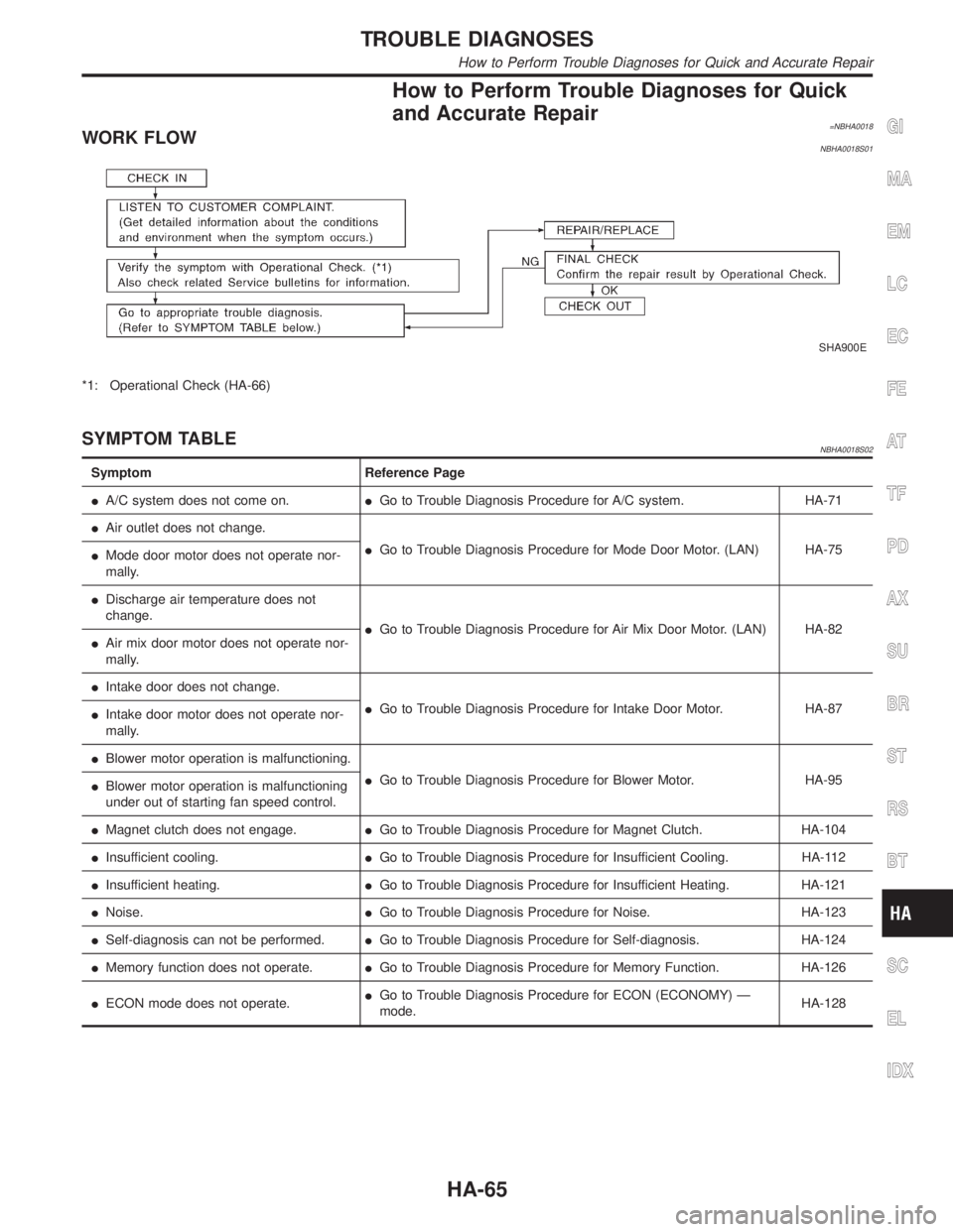
How to Perform Trouble Diagnoses for Quick
and Accurate Repair
=NBHA0018WORK FLOWNBHA0018S01
SHA900E
*1: Operational Check (HA-66)
SYMPTOM TABLENBHA0018S02
Symptom Reference Page
IA/C system does not come on.IGo to Trouble Diagnosis Procedure for A/C system. HA-71
IAir outlet does not change.
IGo to Trouble Diagnosis Procedure for Mode Door Motor. (LAN) HA-75
IMode door motor does not operate nor-
mally.
IDischarge air temperature does not
change.
IGo to Trouble Diagnosis Procedure for Air Mix Door Motor. (LAN) HA-82
IAir mix door motor does not operate nor-
mally.
IIntake door does not change.
IGo to Trouble Diagnosis Procedure for Intake Door Motor. HA-87
IIntake door motor does not operate nor-
mally.
IBlower motor operation is malfunctioning.
IGo to Trouble Diagnosis Procedure for Blower Motor. HA-95
IBlower motor operation is malfunctioning
under out of starting fan speed control.
IMagnet clutch does not engage.IGo to Trouble Diagnosis Procedure for Magnet Clutch. HA-104
IInsufficient cooling.IGo to Trouble Diagnosis Procedure for Insufficient Cooling. HA-112
IInsufficient heating.IGo to Trouble Diagnosis Procedure for Insufficient Heating. HA-121
INoise.IGo to Trouble Diagnosis Procedure for Noise. HA-123
ISelf-diagnosis can not be performed.IGo to Trouble Diagnosis Procedure for Self-diagnosis. HA-124
IMemory function does not operate.IGo to Trouble Diagnosis Procedure for Memory Function. HA-126
IECON mode does not operate.IGo to Trouble Diagnosis Procedure for ECON (ECONOMY) Ð
mode.HA-128
GI
MA
EM
LC
EC
FE
AT
TF
PD
AX
SU
BR
ST
RS
BT
SC
EL
IDX
TROUBLE DIAGNOSES
How to Perform Trouble Diagnoses for Quick and Accurate Repair
HA-65
Page 1868 of 2395

RHA461GA
SHA278FA
6. Check Temperature IncreaseNBHA0019S0206Without Navigation System
IPress the temperature increase button until 32ÉC (85ÉF) is
displayed.
ICheck for hot air at discharge air outlets.
If NG, go to trouble diagnosis procedure for insufficient heating
(HA-121).
If OK, continue with next check.
With Navigation System
ITurn the temperature dial clockwise until 32ÉC (85ÉF) is dis-
played.
ICheck for hot air at discharge air outlets.
If NG, go to trouble diagnosis procedure for insufficient heating
(HA-121).
If OK, continue with next check.
RHA462GA
RHA333HA
7. Check ECON (Economy) ModeNBHA0019S02071. Set the temperature 75ÉF or 25ÉC.
2. Press ECON switch.
3. Display should indicate ECON (no AUTO).
Confirm that the compressor clutch is not engaged (visual
inspection).
(Discharge air and blower speed will depend on ambient, in-
vehicle and set temperatures.)
If NG, go to trouble diagnosis procedure for ECON (Economy)
mode (HA-128).
If OK, continue with next check.
GI
MA
EM
LC
EC
FE
AT
TF
PD
AX
SU
BR
ST
RS
BT
SC
EL
IDX
TROUBLE DIAGNOSES
Operational Check (Cont'd)
HA-69
Page 1920 of 2395

Insufficient Heating
TROUBLE DIAGNOSIS PROCEDURE FOR INSUFFICIENT HEATING=NBHA0097SYMPTOM:
IInsufficient heating
Inspection FlowNBHA0097S01Without Navigation SystemNBHA0097S0101
SHA894EA
*1: HA-66
*2: HA-44
*3: HA-45
*4: HA-45
*5: HA-85*6: STEP-BY-STEP PROCEDURE
(HA-45), see No. 13.
*7: HA-78
*8: HA-90
*9: HA-98*10: HA-82
*11: MA-14
*12: LC-11
*13: LC-16
GI
MA
EM
LC
EC
FE
AT
TF
PD
AX
SU
BR
ST
RS
BT
SC
EL
IDX
TROUBLE DIAGNOSES
Insufficient Heating
HA-121
Page 1921 of 2395

With Navigation SystemNBHA0097S0102
RHA882H
*1: HA-66
*2: HA-44
*3: HA-45
*4: HA-45
*5: HA-85*6: STEP-BY-STEP PROCEDURE
(HA-45), see No. 13.
*7: HA-78
*8: HA-90
*9: HA-98*10: HA-82
*11: MA-14
*12: LC-11
*13: LC-16
TROUBLE DIAGNOSES
Insufficient Heating (Cont'd)
HA-122
Page 1970 of 2395

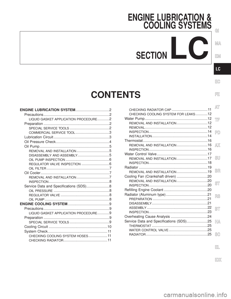
ENGINE LUBRICATION &
COOLING SYSTEMS
SECTION
LC
CONTENTS
ENGINE LUBRICATION SYSTEM..................................2
Precautions ..................................................................2
LIQUID GASKET APPLICATION PROCEDURE............2
Preparation ..................................................................2
SPECIAL SERVICE TOOLS........................................2
COMMERCIAL SERVICE TOOL..................................3
Lubrication Circuit ........................................................3
Oil Pressure Check......................................................4
Oil Pump ......................................................................5
REMOVAL AND INSTALLATION.................................5
DISASSEMBLY AND ASSEMBLY................................5
OIL PUMP INSPECTION............................................6
REGULATOR VALVE INSPECTION............................6
OIL FILTER...............................................................7
Oil Cooler .....................................................................7
REMOVAL AND INSTALLATION.................................7
INSPECTION.............................................................8
Service Data and Specifications (SDS).......................8
OIL PRESSURE........................................................8
REGULATOR VALVE.................................................8
OIL PUMP.................................................................8
ENGINE COOLING SYSTEM..........................................9
Precautions ..................................................................9
LIQUID GASKET APPLICATION PROCEDURE............9
Preparation ..................................................................9
SPECIAL SERVICE TOOLS........................................9
Cooling Circuit ...........................................................10
System Check............................................................ 11
CHECKING COOLING SYSTEM HOSES................... 11
CHECKING RADIATOR............................................ 11
CHECKING RADIATOR CAP.................................... 11
CHECKING COOLING SYSTEM FOR LEAKS............12
Water Pump ...............................................................12
REMOVAL AND INSTALLATION...............................12
REMOVAL...............................................................12
INSPECTION...........................................................14
INSTALLATION........................................................14
Thermostat .................................................................16
REMOVAL AND INSTALLATION...............................16
INSPECTION...........................................................16
Water Control Valve ...................................................17
REMOVAL AND INSTALLATION...............................17
INSPECTION...........................................................18
Radiator .....................................................................19
REMOVAL AND INSTALLATION...............................19
Cooling Fan (Crankshaft driven) ...............................20
REMOVAL AND INSTALLATION...............................20
INSPECTION...........................................................20
Refilling Engine Coolant ............................................20
Radiator (Aluminum type) ..........................................21
PREPARATION.......................................................21
DISASSEMBLY........................................................21
ASSEMBLY.............................................................22
INSPECTION...........................................................23
Overheating Cause Analysis .....................................24
Service Data and Specifications (SDS).....................25
THERMOSTAT........................................................25
WATER CONTROL VALVE.......................................25
RADIATOR..............................................................25
GI
MA
EM
EC
FE
AT
TF
PD
AX
SU
BR
ST
RS
BT
HA
SC
EL
IDX
Page 1993 of 2395

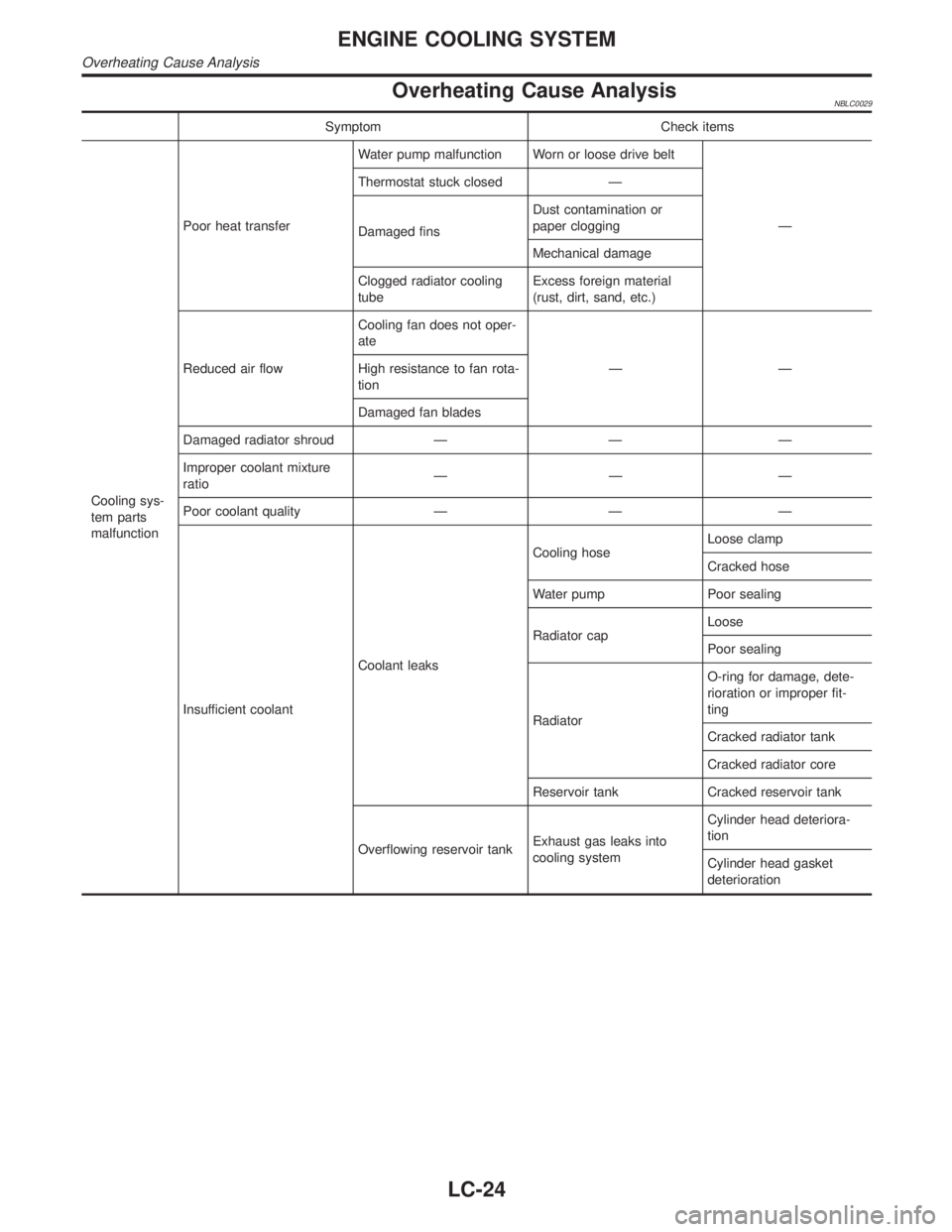
Overheating Cause AnalysisNBLC0029
Symptom Check items
Cooling sys-
tem parts
malfunctionPoor heat transferWater pump malfunction Worn or loose drive belt
Ð Thermostat stuck closed Ð
Damaged finsDust contamination or
paper clogging
Mechanical damage
Clogged radiator cooling
tubeExcess foreign material
(rust, dirt, sand, etc.)
Reduced air flowCooling fan does not oper-
ate
ÐÐ High resistance to fan rota-
tion
Damaged fan blades
Damaged radiator shroud Ð Ð Ð
Improper coolant mixture
ratioÐÐÐ
Poor coolant quality Ð Ð Ð
Insufficient coolantCoolant leaksCooling hoseLoose clamp
Cracked hose
Water pump Poor sealing
Radiator capLoose
Poor sealing
RadiatorO-ring for damage, dete-
rioration or improper fit-
ting
Cracked radiator tank
Cracked radiator core
Reservoir tank Cracked reservoir tank
Overflowing reservoir tankExhaust gas leaks into
cooling systemCylinder head deteriora-
tion
Cylinder head gasket
deterioration
ENGINE COOLING SYSTEM
Overheating Cause Analysis
LC-24
Page 1994 of 2395

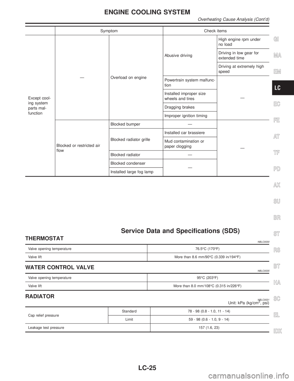
Symptom Check items
Except cool-
ing system
parts mal-
functionÐ Overload on engineAbusive drivingHigh engine rpm under
no load
Driving in low gear for
extended time
Driving at extremely high
speed
Powertrain system malfunc-
tion
Ð Installed improper size
wheels and tires
Dragging brakes
Improper ignition timing
Blocked or restricted air
flowBlocked bumper Ð
Ð Blocked radiator grilleInstalled car brassiere
Mud contamination or
paper clogging
Blocked radiator Ð
Blocked condenser
Ð
Installed large fog lamp
Service Data and Specifications (SDS)
THERMOSTATNBLC0030
Valve opening temperature76.5ÉC (170ÉF)
Valve liftMore than 8.6 mm/90ÉC (0.339 in/194ÉF)
WATER CONTROL VALVENBLC0035
Valve opening temperature95ÉC (203ÉF)
Valve liftMore than 8.0 mm/108ÉC (0.315 in/226ÉF)
RADIATORNBLC0031Unit: kPa (kg/cm2, psi)
Cap relief pressureStandard 78 - 98 (0.8 - 1.0, 11 - 14)
Limit 59 - 98 (0.6 - 1.0,9-14)
Leakage test pressure157 (1.6, 23)
GI
MA
EM
EC
FE
AT
TF
PD
AX
SU
BR
ST
RS
BT
HA
SC
EL
IDX
ENGINE COOLING SYSTEM
Overheating Cause Analysis (Cont'd)
LC-25