2001 INFINITI QX4 checking oil
[x] Cancel search: checking oilPage 1811 of 2395
Tool number
(Kent-Moore No.)
Tool nameDescription
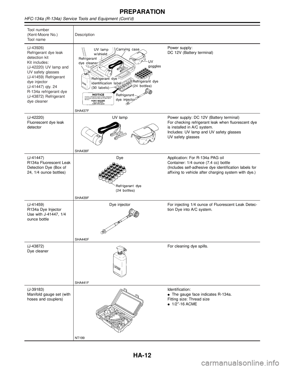
(J-43926)
Refrigerant dye leak
detection kit
Kit includes:
(J-42220) UV lamp and
UV safety glasses
(J-41459) Refrigerant
dye injector
(J-41447) qty. 24
R-134a refrigerant dye
(J-43872) Refrigerant
dye cleaner
SHA437F
Power supply:
DC 12V (Battery terminal)
(J-42220)
Fluorescent dye leak
detectorUV lamp
SHA438F
Power supply: DC 12V (Battery terminal)
For checking refrigerant leak when fluorescent dye
is installed in A/C system.
Includes: UV lamp and UV safety glasses
UV safety glasses
(J-41447)
R134a Fluorescent Leak
Detection Dye (Box of
24, 1/4 ounce bottles)Dye
SHA439F
Application: For R-134a PAG oil
Container: 1/4 ounce (7.4 cc) bottle
(Includes self-adhesive dye identification labels for
affixing to vehicle after charging system with dye.)
(J-41459)
R134a Dye Injector
Use with J-41447, 1/4
ounce bottleDye injector
SHA440F
For injecting 1/4 ounce of Fluorescent Leak Detec-
tion Dye into A/C system.
(J-43872)
Dye cleaner
SHA441F
For cleaning dye spills.
(J-39183)
Manifold gauge set (with
hoses and couplers)
NT199
Identification:
IThe gauge face indicates R-134a.
Fitting size: Thread size
I1/2²-16 ACME
PREPARATION
HFC-134a (R-134a) Service Tools and Equipment (Cont'd)
HA-12
Page 1812 of 2395
Tool number
(Kent-Moore No.)
Tool nameDescription
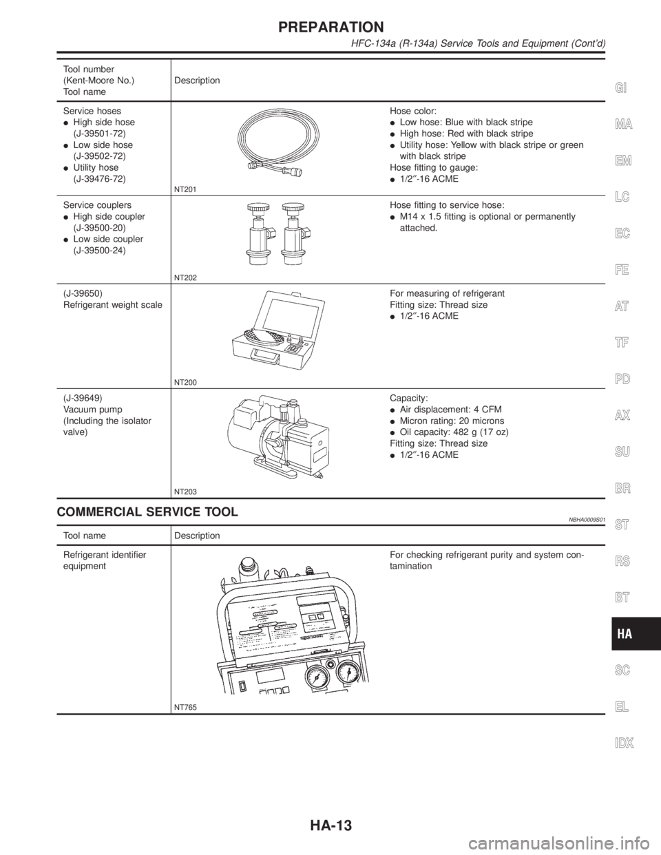
Service hoses
IHigh side hose
(J-39501-72)
ILow side hose
(J-39502-72)
IUtility hose
(J-39476-72)
NT201
Hose color:
ILow hose: Blue with black stripe
IHigh hose: Red with black stripe
IUtility hose: Yellow with black stripe or green
with black stripe
Hose fitting to gauge:
I1/2²-16 ACME
Service couplers
IHigh side coupler
(J-39500-20)
ILow side coupler
(J-39500-24)
NT202
Hose fitting to service hose:
IM14 x 1.5 fitting is optional or permanently
attached.
(J-39650)
Refrigerant weight scale
NT200
For measuring of refrigerant
Fitting size: Thread size
I1/2²-16 ACME
(J-39649)
Vacuum pump
(Including the isolator
valve)
NT203
Capacity:
IAir displacement: 4 CFM
IMicron rating: 20 microns
IOil capacity: 482 g (17 oz)
Fitting size: Thread size
I1/2²-16 ACME
COMMERCIAL SERVICE TOOLNBHA0009S01
Tool name Description
Refrigerant identifier
equipment
NT765
For checking refrigerant purity and system con-
tamination
GI
MA
EM
LC
EC
FE
AT
TF
PD
AX
SU
BR
ST
RS
BT
SC
EL
IDX
PREPARATION
HFC-134a (R-134a) Service Tools and Equipment (Cont'd)
HA-13
Page 1945 of 2395
Maintenance of Lubricant Quantity in
Compressor
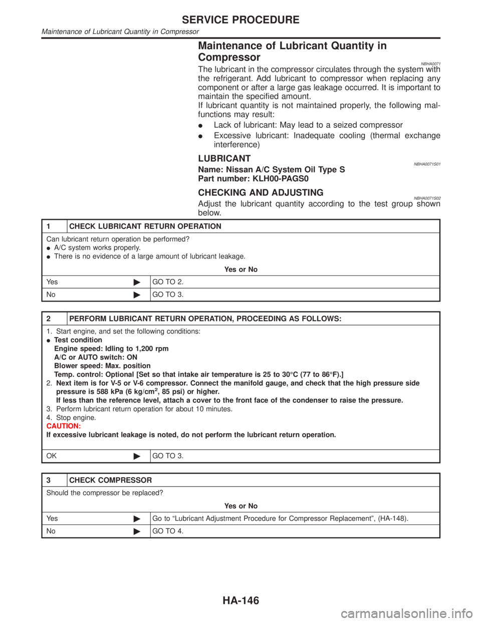
NBHA0071The lubricant in the compressor circulates through the system with
the refrigerant. Add lubricant to compressor when replacing any
component or after a large gas leakage occurred. It is important to
maintain the specified amount.
If lubricant quantity is not maintained properly, the following mal-
functions may result:
ILack of lubricant: May lead to a seized compressor
IExcessive lubricant: Inadequate cooling (thermal exchange
interference)
LUBRICANTNBHA0071S01Name: Nissan A/C System Oil Type S
Part number: KLH00-PAGS0
CHECKING AND ADJUSTINGNBHA0071S02Adjust the lubricant quantity according to the test group shown
below.
1 CHECK LUBRICANT RETURN OPERATION
Can lubricant return operation be performed?
IA/C system works properly.
IThere is no evidence of a large amount of lubricant leakage.
YesorNo
Ye s©GO TO 2.
No©GO TO 3.
2 PERFORM LUBRICANT RETURN OPERATION, PROCEEDING AS FOLLOWS:
1. Start engine, and set the following conditions:
ITest condition
Engine speed: Idling to 1,200 rpm
A/C or AUTO switch: ON
Blower speed: Max. position
Temp. control: Optional [Set so that intake air temperature is 25 to 30ÉC (77 to 86ÉF).]
2.Next item is for V-5 or V-6 compressor. Connect the manifold gauge, and check that the high pressure side
pressure is 588 kPa (6 kg/cm
2, 85 psi) or higher.
If less than the reference level, attach a cover to the front face of the condenser to raise the pressure.
3. Perform lubricant return operation for about 10 minutes.
4. Stop engine.
CAUTION:
If excessive lubricant leakage is noted, do not perform the lubricant return operation.
OK©GO TO 3.
3 CHECK COMPRESSOR
Should the compressor be replaced?
YesorNo
Ye s©Go to ªLubricant Adjustment Procedure for Compressor Replacementº, (HA-148).
No©GO TO 4.
SERVICE PROCEDURE
Maintenance of Lubricant Quantity in Compressor
HA-146
Page 1962 of 2395
Brake fluid change ...........................................BR-7
Brake fluid level .............................................MA-25
Brake fluid level and line check .......................BR-7
Brake hydraulic line ..........................................BR-9
Brake inspection ............................................MA-25
Brake lines and cables inspection .................MA-25
Brake lining wear temporary checking ..........MA-26
Brake master cylinder ....................................BR-16
Brake pedal ....................................................BR-14
Bulb specifications ........................................EL-456
Bumper, front ..................................................BT-12
Bumper, rear ...................................................BT-15
BYPS/V - Wiring diagram ....................EC-587, 594
C
Camshaft inspection ......................................EM-42
Camshaft position sensor (PHASE) .............EC-342
Canister-See EVAP canister ..........................EC-32
Center bearing assembly (propeller
shaft) .............................................................PD-9
Center bearing disassembly (propeller
shaft) .............................................................PD-7
Center case (Transfer) ..................................TF-123
CHARGE - Wiring diagram ............................SC-20
Charging system ............................................SC-19
Chassis and body maintenance ....................MA-21
CHIME - Wiring diagram...............................EL-127
CIGAR - Wiring diagram ...............................EL-148
Cigarette lighter.............................................EL-148
Circuit breaker.................................................EL-16
CKPS - Wiring diagram ................................EC-334
Closed loop control (Left bank) ....................EC-491
Closed loop control (Right bank) .................EC-491
Closed throttle position switch .....................EC-431
Clutch drum (Transfer) ..................................TF-125
Clutch force release limit adjustment .............TF-39
Clutch pressure switch (Transfer) .................TF-111
Coil spring (front)..............................................SU-8
Coil spring (rear) ............................................SU-18
Collision diagnosis..........................................RS-59
Combination lamp, front, removal and
installation ...................................................BT-12
Combination lamp, rear, removal and
installation ...................................................BT-35
Combination meter..........................................EL-94
Combination meter removal and instal-
lation - See Instrument panel ......................BT-21
Combination switch .........................................EL-28
COMPAS - Wiring diagram ...........................EL-111
Compass .......................................................EL-110
Component Location (auto A/C).....................HA-27
Compression pressure ...................................EM-14
Compressor clutch removal and
installation .................................................HA-150
Compressor precaution ....................................HA-6
Compressor special service tool ....................HA-10
Connecting rod...............................................EM-65
Connecting rod bearing clearance.................EM-69
Connecting rod bushing clearance ................EM-70Connector inspection .......................................GI-21
Console box - See Instrument panel ..............BT-21
CONSULT for ABS .........................................BR-43
CONSULT for all-mode 4WD ..........................TF-30
CONSULT for engine .....................................EC-81
CONSULT-II general information .....................GI-38
Control valve (A/T) ........................................AT-301
Control valve (Transfer) ................................TF-128
Converter housing installation .......................AT-278
Coolant mixture ratio......................................MA-12
Coolant replacement ......................................MA-14
Cooling circuit (engine) ...................................LC-10
``Crankcase emission control system -
See positive crankcase ventilation''............EC-38
Crankshaft ......................................................EM-67
Crankshaft position sensor (POS) ...............EC-334
Crankshaft position sensor (POS)
chipping ....................................................EC-517
Crankshaft position sensor (REF) ................EC-510
Cruise control - See ASCD ...........................EL-221
Cylinder block ................................................EM-61
Cylinder head .................................................EM-38
Cylinder head bolt tightening .........................EM-49
D
Data link connector for Consult......................EC-81
Daytime light system.......................................EL-46
Daytime running light - See Daytime
light system .................................................EL-46
DEF - Wiring diagram ...................................EL-153
Detonation sensor - See Knock sensor .......EC-328
Diagnostic trouble code (DTC) for OBD
system ....................................................EC-8, 60
Diagnostic trouble code (DTC) inspec-
tion priority chart .......................................EC-116
Differential carrier assembly.....................PD-30, 57
Differential carrier disassembly ......................PD-44
Differential gear oil replacement ....................MA-24
Dimensions ......................................................GI-43
D/LOCK - Wiring diagram .............................EL-256
Dome light - See Interior lamp .......................EL-88
Door glass .......................................................BT-18
Door lock .........................................................BT-18
Door mirror ......................................................BT-56
Door trim .........................................................BT-30
Door, front .......................................................BT-18
Door, rear ........................................................BT-20
Drive belt inspection ......................................MA-13
Drive chain (Transfer) ...................................TF-125
Drive pinion diff. inspection ......................PD-23, 47
Drive pinion height ...................................PD-25, 53
Drive plate runout ..........................................EM-70
Drive shaft (front)............................................AX-10
Dropping resistor (A/T) ..................................AT-167
DTC work support ..........................................EC-93
DTRL - Wiring diagram ...................................EL-51
GI
MA
EM
LC
EC
FE
AT
TF
PD
AX
SU
BR
ST
RS
BT
HA
SC
EL
ALPHABETICAL INDEX
IDX-3
Page 1970 of 2395
ENGINE LUBRICATION &
COOLING SYSTEMS
SECTION
LC
CONTENTS
ENGINE LUBRICATION SYSTEM..................................2
Precautions ..................................................................2
LIQUID GASKET APPLICATION PROCEDURE............2
Preparation ..................................................................2
SPECIAL SERVICE TOOLS........................................2
COMMERCIAL SERVICE TOOL..................................3
Lubrication Circuit ........................................................3
Oil Pressure Check......................................................4
Oil Pump ......................................................................5
REMOVAL AND INSTALLATION.................................5
DISASSEMBLY AND ASSEMBLY................................5
OIL PUMP INSPECTION............................................6
REGULATOR VALVE INSPECTION............................6
OIL FILTER...............................................................7
Oil Cooler .....................................................................7
REMOVAL AND INSTALLATION.................................7
INSPECTION.............................................................8
Service Data and Specifications (SDS).......................8
OIL PRESSURE........................................................8
REGULATOR VALVE.................................................8
OIL PUMP.................................................................8
ENGINE COOLING SYSTEM..........................................9
Precautions ..................................................................9
LIQUID GASKET APPLICATION PROCEDURE............9
Preparation ..................................................................9
SPECIAL SERVICE TOOLS........................................9
Cooling Circuit ...........................................................10
System Check............................................................ 11
CHECKING COOLING SYSTEM HOSES................... 11
CHECKING RADIATOR............................................ 11
CHECKING RADIATOR CAP.................................... 11
CHECKING COOLING SYSTEM FOR LEAKS............12
Water Pump ...............................................................12
REMOVAL AND INSTALLATION...............................12
REMOVAL...............................................................12
INSPECTION...........................................................14
INSTALLATION........................................................14
Thermostat .................................................................16
REMOVAL AND INSTALLATION...............................16
INSPECTION...........................................................16
Water Control Valve ...................................................17
REMOVAL AND INSTALLATION...............................17
INSPECTION...........................................................18
Radiator .....................................................................19
REMOVAL AND INSTALLATION...............................19
Cooling Fan (Crankshaft driven) ...............................20
REMOVAL AND INSTALLATION...............................20
INSPECTION...........................................................20
Refilling Engine Coolant ............................................20
Radiator (Aluminum type) ..........................................21
PREPARATION.......................................................21
DISASSEMBLY........................................................21
ASSEMBLY.............................................................22
INSPECTION...........................................................23
Overheating Cause Analysis .....................................24
Service Data and Specifications (SDS).....................25
THERMOSTAT........................................................25
WATER CONTROL VALVE.......................................25
RADIATOR..............................................................25
GI
MA
EM
EC
FE
AT
TF
PD
AX
SU
BR
ST
RS
BT
HA
SC
EL
IDX
Page 1996 of 2395
MAINTENANCE
SECTION
MA
CONTENTS
PRECAUTIONS...............................................................2
Supplemental Restraint System (SRS)²AIR
BAG²and²SEAT BELT PRE-TENSIONER²...............2
PREPARATION...............................................................3
Special Service Tool ....................................................3
Commercial Service Tool .............................................3
GENERAL MAINTENANCE............................................4
PERIODIC MAINTENANCE............................................6
Schedule 1 ...................................................................7
EMISSION CONTROL SYSTEM MAINTENANCE.........7
CHASSIS AND BODY MAINTENANCE........................8
Schedule 2 ...................................................................9
EMISSION CONTROL SYSTEM MAINTENANCE.........9
CHASSIS AND BODY MAINTENANCE......................10
RECOMMENDED FLUIDS AND LUBRICANTS........... 11
Fluids and Lubricants ................................................ 11
SAE Viscosity Number ..............................................12
GASOLINE ENGINE OIL..........................................12
GEAR OIL...............................................................12
Anti-freeze Coolant Mixture Ratio .............................12
ENGINE MAINTENANCE..............................................13
Checking Drive Belts .................................................13
Changing Engine Coolant..........................................14
-DRAINING ENGINE COOLANT-..............................14
-REFILLING ENGINE COOLANT-..............................15
-FLUSHING COOLING SYSTEM-..............................16
Checking Fuel Lines ..................................................16
Changing Fuel Filter ..................................................16
WITH CONSULT-II..............................................16
WITHOUT CONSULT-II.......................................17
Changing Air Cleaner Filter .......................................17
VISCOUS PAPER TYPE...........................................17
Changing Engine Oil..................................................18
Changing Oil Filter .....................................................18
Changing Spark Plugs ...............................................19
Checking EVAP Vapor Lines .....................................20
CHASSIS AND BODY MAINTENANCE.......................21
Checking Exhaust System.........................................21
Checking A/T Fluid ....................................................21
Changing A/T Fluid ....................................................21Checking All-mode 4WD Transfer Fluid ....................22
Changing All-mode 4WD Transfer Fluid ....................22
Checking Propeller Shaft ...........................................23
Greasing Propeller Shaft ...........................................23
Checking Differential Gear Oil ...................................23
Changing Differential Gear Oil ..................................24
LIMITED-SLIP DIFFERENTIAL GEAR........................24
Balancing Wheels ......................................................24
Tire Rotation ..............................................................24
Checking Brake Fluid Level and Leaks.....................25
Checking Brake Lines and Cables ............................25
Checking Disc Brake .................................................25
ROTOR...................................................................25
CALIPER.................................................................25
PAD........................................................................25
Checking Drum Brake ...............................................26
WHEEL CYLINDER..................................................26
DRUM.....................................................................26
LINING....................................................................26
TEMPORARY METHOD FOR CHECKING LINING
WEAR
.....................................................................26
Checking Steering Gear, Linkage and Transfer
Gear ...........................................................................26
STEERING GEAR....................................................26
STEERING LINKAGE...............................................26
STEERING TRANSFER GEAR..................................26
Checking Power Steering Fluid and Lines ................27
CHECKING FLUID LEVEL........................................27
CHECKING LINES...................................................27
Lubricating Locks, Hinges and Hood Latches...........27
Checking Seat Belts, Buckles, Retractors,
Anchors and Adjusters...............................................28
SERVICE DATA AND SPECIFICATIONS (SDS).........29
Engine Maintenance ..................................................29
DRIVE BELT DEFLECTION......................................29
DRIVE BELT TENSION............................................29
SPARK PLUG TYPE................................................29
Chassis and Body Maintenance ................................29
WHEEL BALANCE...................................................29
GI
EM
LC
EC
FE
AT
TF
PD
AX
SU
BR
ST
RS
BT
HA
SC
EL
IDX
Page 1998 of 2395
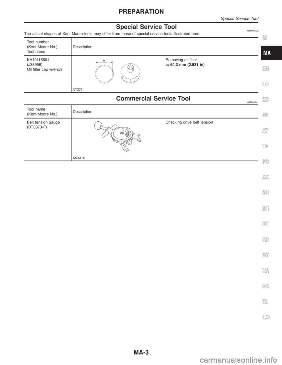
Special Service ToolNBMA0002The actual shapes of Kent-Moore tools may differ from those of special service tools illustrated here.
Tool number
(Kent-Moore No.)
Tool nameDescription
KV10115801
(J38956)
Oil filter cap wrench
NT375
Removing oil filter
a: 64.3 mm (2.531 in)
Commercial Service ToolNBMA0041
Tool name
(Kent-Moore No.)Description
Belt tension gauge
(BT3373-F)
AMA126
Checking drive belt tension
GI
EM
LC
EC
FE
AT
TF
PD
AX
SU
BR
ST
RS
BT
HA
SC
EL
IDX
PREPARATION
Special Service Tool
MA-3
Page 2008 of 2395

Checking Drive BeltsNBMA0010
SMA091D
1. Inspect belt for cracks, fraying, wear and oil. If necessary,
replace.
2. Inspect drive belt deflection or tension at a point on the belt
midway between pulleys.
3. Check belt tension using belt tension gauge (BT3373-F or
equivalent).
Inspect drive belt deflection or tension when engine is cold.
Adjust if belt deflections exceed the limit or if belt tension is
not within specifications.
Belt deflection and tension
Deflection adjustment Unit: mm (in) Tension adjustment *1 Unit: N (kg, lb)
Used belt
New beltUsed belt
New belt
Limit After adjustment Limit After adjustment
Alternator
Power steering
oil pump
Fan7 (0.28)4-5
(0.16 - 0.20)3.5 - 4.5
(0.138 - 0.177)294 (30, 66)730 - 818 (74.4 -
83.5, 164 - 184)838 - 926 (85.4 -
94.5, 188 - 208)
Air conditioner
compressor12 (0.47)9-10
(0.35 - 0.39)8-9
(0.31 - 0.35)196 (20, 44)348 - 436 (35.5 -
44.5, 78 - 98)470 - 559 (47.9 -
57.0, 106 - 126)
Applied pushing
force98 N (10 kg, 22 lb) Ð
*1 If belt tension gauge cannot be installed at check points shown, check drive belt tension at a different location on the belt.
GI
EM
LC
EC
FE
AT
TF
PD
AX
SU
BR
ST
RS
BT
HA
SC
EL
IDX
ENGINE MAINTENANCE
Checking Drive Belts
MA-13