2001 INFINITI QX4 antenna
[x] Cancel search: antennaPage 1582 of 2395
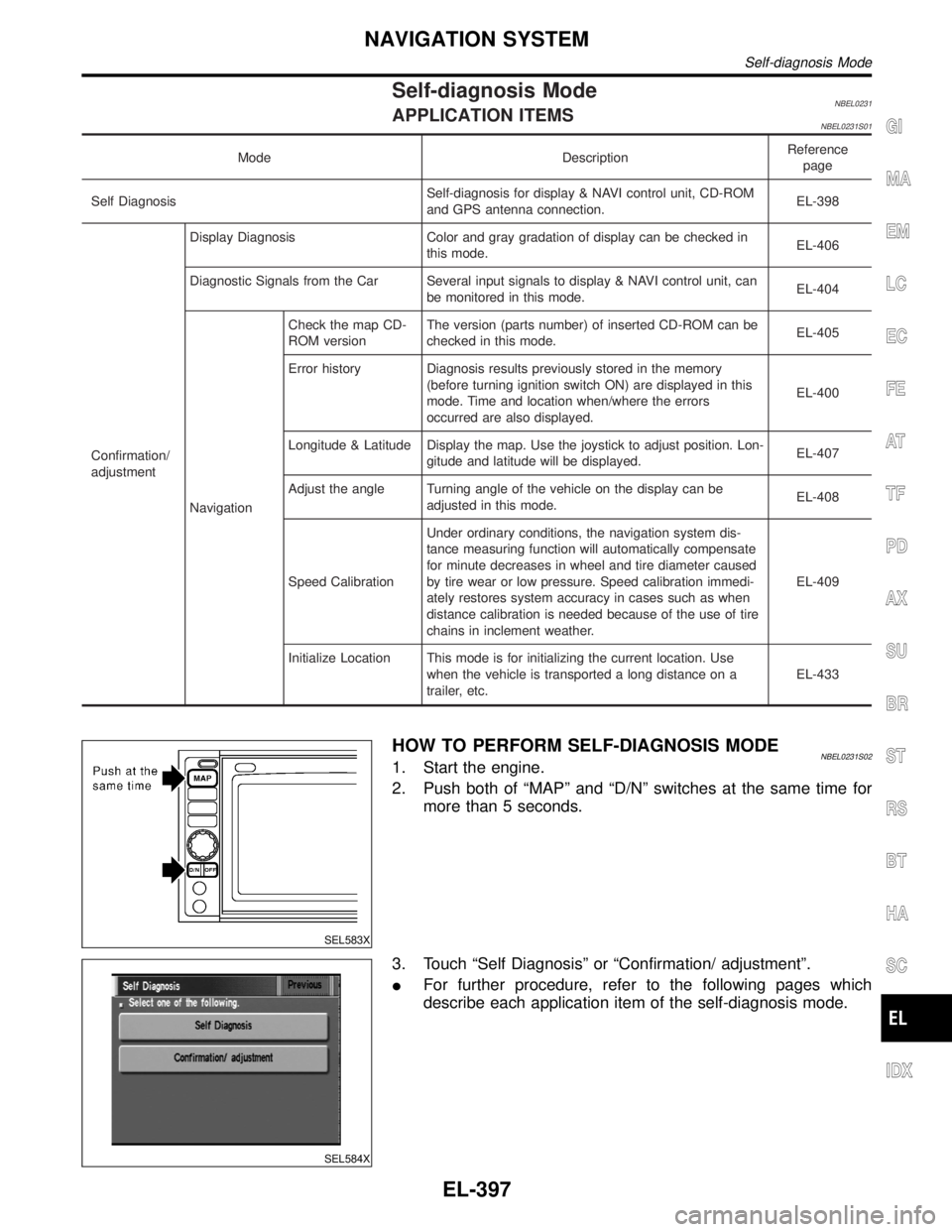
Self-diagnosis ModeNBEL0231APPLICATION ITEMSNBEL0231S01
Mode DescriptionReference
page
Self DiagnosisSelf-diagnosis for display & NAVI control unit, CD-ROM
and GPS antenna connection.EL-398
Confirmation/
adjustmentDisplay Diagnosis Color and gray gradation of display can be checked in
this mode.EL-406
Diagnostic Signals from the Car Several input signals to display & NAVI control unit, can
be monitored in this mode.EL-404
NavigationCheck the map CD-
ROM versionThe version (parts number) of inserted CD-ROM can be
checked in this mode.EL-405
Error history Diagnosis results previously stored in the memory
(before turning ignition switch ON) are displayed in this
mode. Time and location when/where the errors
occurred are also displayed.EL-400
Longitude & Latitude Display the map. Use the joystick to adjust position. Lon-
gitude and latitude will be displayed.EL-407
Adjust the angle Turning angle of the vehicle on the display can be
adjusted in this mode.EL-408
Speed CalibrationUnder ordinary conditions, the navigation system dis-
tance measuring function will automatically compensate
for minute decreases in wheel and tire diameter caused
by tire wear or low pressure. Speed calibration immedi-
ately restores system accuracy in cases such as when
distance calibration is needed because of the use of tire
chains in inclement weather.EL-409
Initialize Location This mode is for initializing the current location. Use
when the vehicle is transported a long distance on a
trailer, etc.EL-433
SEL583X
HOW TO PERFORM SELF-DIAGNOSIS MODENBEL0231S021. Start the engine.
2. Push both of ªMAPº and ªD/Nº switches at the same time for
more than 5 seconds.
SEL584X
3. Touch ªSelf Diagnosisº or ªConfirmation/ adjustmentº.
IFor further procedure, refer to the following pages which
describe each application item of the self-diagnosis mode.
GI
MA
EM
LC
EC
FE
AT
TF
PD
AX
SU
BR
ST
RS
BT
HA
SC
IDX
NAVIGATION SYSTEM
Self-diagnosis Mode
EL-397
Page 1583 of 2395

SEL584X
ªSelf DiagnosisºNBEL0231S02011. Start the engine.
2. Push both ªMAPº and ªD/Nº switches at the same time for more
than 5 seconds.
3. Touch ªSelf Diagnosisº.
SEL585X
4. Self-diagnosis will be performed.
SEL586X
5. Diagnosis results will be displayed. Diagnosis results are indi-
cated by display color. For details refer to ªSELF-DIAGNOSIS
RESULTSº.
SEL587X
To obtain detailed diagnosis results on the screen, touch ªNaviga-
tionº or ªGPS Antennaº.
NAVIGATION SYSTEM
Self-diagnosis Mode (Cont'd)
EL-398
Page 1584 of 2395
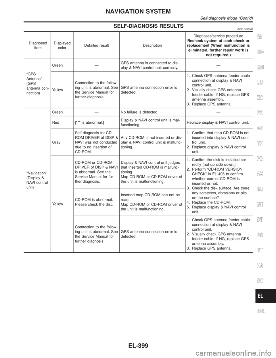
SELF-DIAGNOSIS RESULTS=NBEL0231S03
Diagnosed
itemDisplayed
colorDetailed result DescriptionDiagnoses/service procedure
Recheck system at each check or
replacement (When malfunction is
eliminated, further repair work is
not required.)
ªGPS
Antennaº
(GPS
antenna con-
nection)Green ÐGPS antenna is connected to dis-
play & NAVI control unit correctly.Ð
YellowConnection to the follow-
ing unit is abnormal. See
the Service Manual for
further diagnosis.GPS antenna connection error is
detected.1. Check GPS antenna feeder cable
connection at display & NAVI
control unit.
2. Visually check GPS antenna
feeder cable. If NG, replace GPS
antenna assembly.
3. Replace GPS antenna.
ªNavigationº
(Display &
NAVI control
unit)Green Ð No failure is detected. Ð
Red [*** is abnormal.]Display & NAVI control unit is mal-
functioning.Replace display & NAVI control unit.
GraySelf-diagnosis for CD-
ROM DRIVER of DISP &
NAVI was not conducted
due to no insertion of
CD-ROM.Any CD-ROM is not inserted or dis-
play & NAVI control unit is malfunc-
tioning.1. Confirm that map CD-ROM is not
inserted into display & NAVI con-
trol unit.
2. Replace display & NAVI control
unit.
YellowCD-ROM or CD-ROM
DRIVER of DISP & NAVI
is abnormal. See the
Service Manual for fur-
ther diagnosis.Display & NAVI control unit judges
that inserted CD-ROM is malfunc-
tioning.
Map CD-ROM or CD-ROM driver of
the unit is malfunctioning.1. Confirm the disk is installed cor-
rectly (not up side down.)
2. Perform ªCD-ROM VERSION
CHECKº in EL-405 to confirm
whether correct CD-ROM is
inserted or not.
3. Check the disk surface. Are there
any scratches, abrasions or pits
on the surface?
4. Replace the CD-ROM.
5. Replace display & NAVI control
unit. CD-ROM is abnormal.
Please check the disc.Inserted map CD-ROM can not be
read.
Map CD-ROM or CD-ROM driver of
the unit is malfunctioning.
Connection to the follow-
ing unit is abnormal. See
the Service Manual for
further diagnosis.GPS antenna connection error is
detected.1. Check GPS antenna feeder cable
connection at display & NAVI
control unit.
2. Visually check GPS antenna
feeder cable. If NG, replace GPS
antenna assembly.
3. Replace GPS antenna.
GI
MA
EM
LC
EC
FE
AT
TF
PD
AX
SU
BR
ST
RS
BT
HA
SC
IDX
NAVIGATION SYSTEM
Self-diagnosis Mode (Cont'd)
EL-399
Page 1587 of 2395
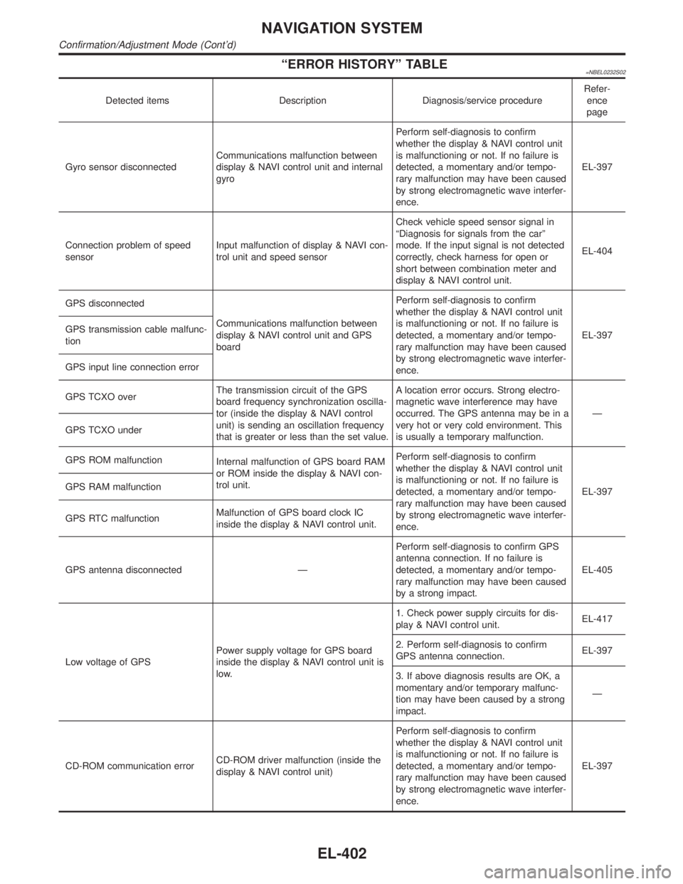
ªERROR HISTORYº TABLE=NBEL0232S02
Detected items Description Diagnosis/service procedureRefer-
ence
page
Gyro sensor disconnectedCommunications malfunction between
display & NAVI control unit and internal
gyroPerform self-diagnosis to confirm
whether the display & NAVI control unit
is malfunctioning or not. If no failure is
detected, a momentary and/or tempo-
rary malfunction may have been caused
by strong electromagnetic wave interfer-
ence.EL-397
Connection problem of speed
sensorInput malfunction of display & NAVI con-
trol unit and speed sensorCheck vehicle speed sensor signal in
ªDiagnosis for signals from the carº
mode. If the input signal is not detected
correctly, check harness for open or
short between combination meter and
display & NAVI control unit.EL-404
GPS disconnected
Communications malfunction between
display & NAVI control unit and GPS
boardPerform self-diagnosis to confirm
whether the display & NAVI control unit
is malfunctioning or not. If no failure is
detected, a momentary and/or tempo-
rary malfunction may have been caused
by strong electromagnetic wave interfer-
ence.EL-397 GPS transmission cable malfunc-
tion
GPS input line connection error
GPS TCXO overThe transmission circuit of the GPS
board frequency synchronization oscilla-
tor (inside the display & NAVI control
unit) is sending an oscillation frequency
that is greater or less than the set value.A location error occurs. Strong electro-
magnetic wave interference may have
occurred. The GPS antenna may be in a
very hot or very cold environment. This
is usually a temporary malfunction.Ð
GPS TCXO under
GPS ROM malfunction
Internal malfunction of GPS board RAM
or ROM inside the display & NAVI con-
trol unit.Perform self-diagnosis to confirm
whether the display & NAVI control unit
is malfunctioning or not. If no failure is
detected, a momentary and/or tempo-
rary malfunction may have been caused
by strong electromagnetic wave interfer-
ence.EL-397 GPS RAM malfunction
GPS RTC malfunctionMalfunction of GPS board clock IC
inside the display & NAVI control unit.
GPS antenna disconnected ÐPerform self-diagnosis to confirm GPS
antenna connection. If no failure is
detected, a momentary and/or tempo-
rary malfunction may have been caused
by a strong impact.EL-405
Low voltage of GPSPower supply voltage for GPS board
inside the display & NAVI control unit is
low.1. Check power supply circuits for dis-
play & NAVI control unit.EL-417
2. Perform self-diagnosis to confirm
GPS antenna connection.EL-397
3. If above diagnosis results are OK, a
momentary and/or temporary malfunc-
tion may have been caused by a strong
impact.Ð
CD-ROM communication errorCD-ROM driver malfunction (inside the
display & NAVI control unit)Perform self-diagnosis to confirm
whether the display & NAVI control unit
is malfunctioning or not. If no failure is
detected, a momentary and/or tempo-
rary malfunction may have been caused
by strong electromagnetic wave interfer-
ence.EL-397
NAVIGATION SYSTEM
Confirmation/Adjustment Mode (Cont'd)
EL-402
Page 1602 of 2395
SEL611X
6. To delete all the stored places in the ªAddress Bookº, ªAvoid
Areaº and ªPrevious Dest.º, select ªYesº.
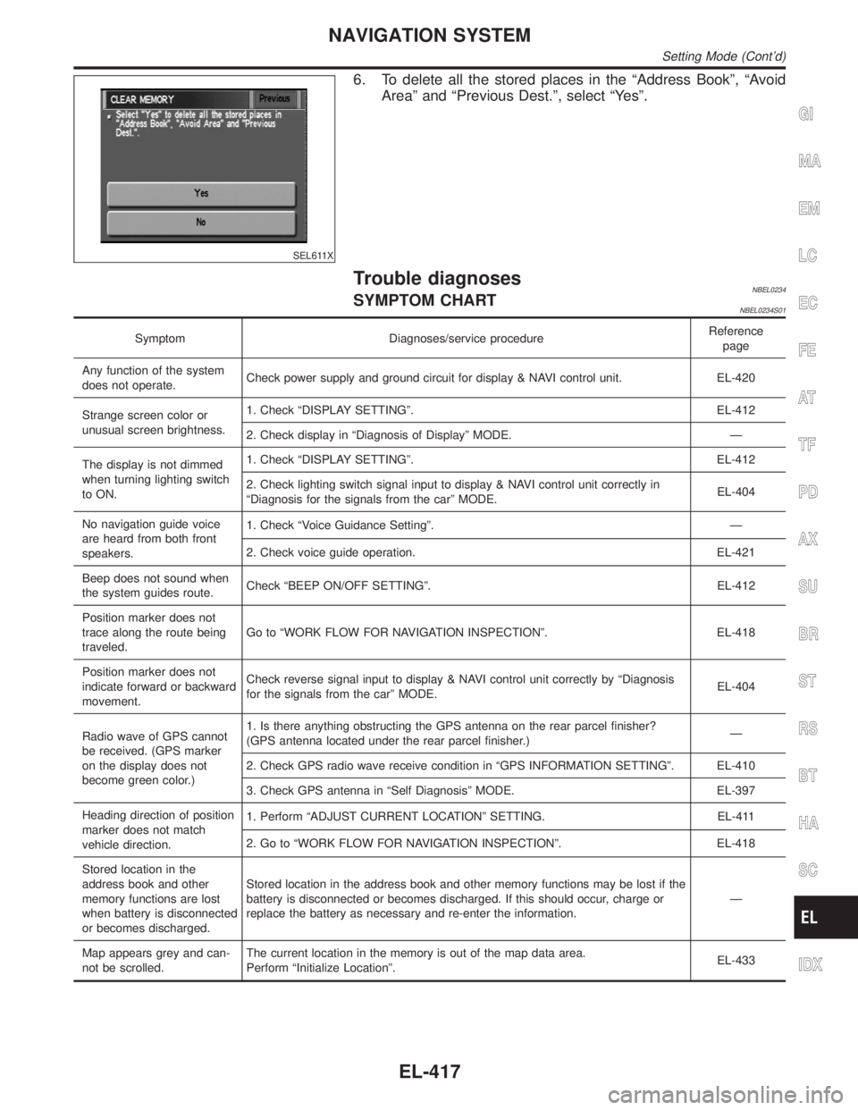
Trouble diagnosesNBEL0234SYMPTOM CHARTNBEL0234S01
Symptom Diagnoses/service procedureReference
page
Any function of the system
does not operate.Check power supply and ground circuit for display & NAVI control unit. EL-420
Strange screen color or
unusual screen brightness.1. Check ªDISPLAY SETTINGº. EL-412
2. Check display in ªDiagnosis of Displayº MODE. Ð
The display is not dimmed
when turning lighting switch
to ON.1. Check ªDISPLAY SETTINGº. EL-412
2. Check lighting switch signal input to display & NAVI control unit correctly in
ªDiagnosis for the signals from the carº MODE.EL-404
No navigation guide voice
are heard from both front
speakers.1. Check ªVoice Guidance Settingº. Ð
2. Check voice guide operation. EL-421
Beep does not sound when
the system guides route.Check ªBEEP ON/OFF SETTINGº. EL-412
Position marker does not
trace along the route being
traveled.Go to ªWORK FLOW FOR NAVIGATION INSPECTIONº. EL-418
Position marker does not
indicate forward or backward
movement.Check reverse signal input to display & NAVI control unit correctly by ªDiagnosis
for the signals from the carº MODE.EL-404
Radio wave of GPS cannot
be received. (GPS marker
on the display does not
become green color.)1. Is there anything obstructing the GPS antenna on the rear parcel finisher?
(GPS antenna located under the rear parcel finisher.)Ð
2. Check GPS radio wave receive condition in ªGPS INFORMATION SETTINGº. EL-410
3. Check GPS antenna in ªSelf Diagnosisº MODE. EL-397
Heading direction of position
marker does not match
vehicle direction.1. Perform ªADJUST CURRENT LOCATIONº SETTING. EL-411
2. Go to ªWORK FLOW FOR NAVIGATION INSPECTIONº. EL-418
Stored location in the
address book and other
memory functions are lost
when battery is disconnected
or becomes discharged.Stored location in the address book and other memory functions may be lost if the
battery is disconnected or becomes discharged. If this should occur, charge or
replace the battery as necessary and re-enter the information.Ð
Map appears grey and can-
not be scrolled.The current location in the memory is out of the map data area.
Perform ªInitialize Locationº.EL-433
GI
MA
EM
LC
EC
FE
AT
TF
PD
AX
SU
BR
ST
RS
BT
HA
SC
IDX
NAVIGATION SYSTEM
Setting Mode (Cont'd)
EL-417
Page 1604 of 2395
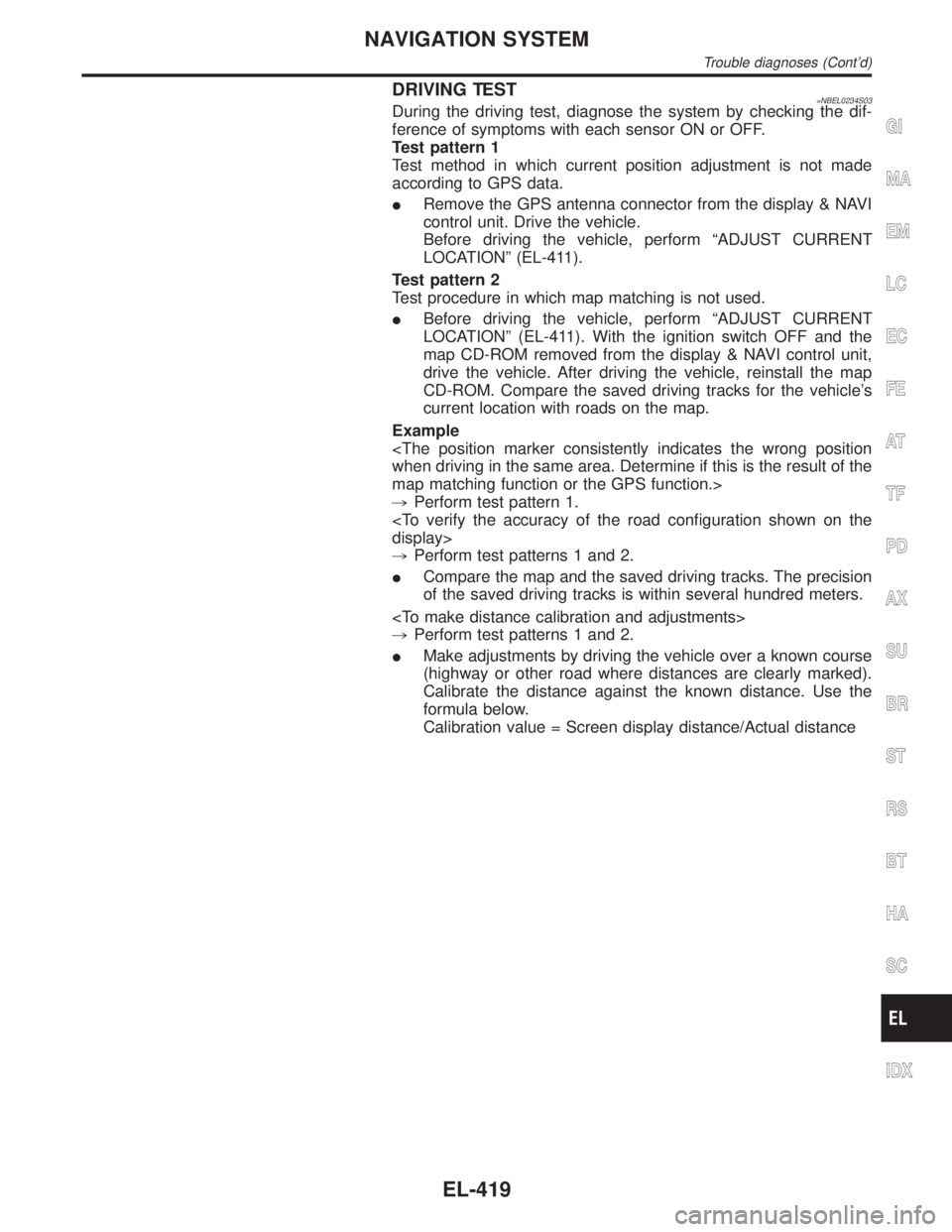
DRIVING TEST=NBEL0234S03During the driving test, diagnose the system by checking the dif-
ference of symptoms with each sensor ON or OFF.
Test pattern 1
Test method in which current position adjustment is not made
according to GPS data.
IRemove the GPS antenna connector from the display & NAVI
control unit. Drive the vehicle.
Before driving the vehicle, perform ªADJUST CURRENT
LOCATIONº (EL-411).
Test pattern 2
Test procedure in which map matching is not used.
IBefore driving the vehicle, perform ªADJUST CURRENT
LOCATIONº (EL-411). With the ignition switch OFF and the
map CD-ROM removed from the display & NAVI control unit,
drive the vehicle. After driving the vehicle, reinstall the map
CD-ROM. Compare the saved driving tracks for the vehicle's
current location with roads on the map.
Example
map matching function or the GPS function.>
,Perform test pattern 1.
,Perform test patterns 1 and 2.
ICompare the map and the saved driving tracks. The precision
of the saved driving tracks is within several hundred meters.
,Perform test patterns 1 and 2.
IMake adjustments by driving the vehicle over a known course
(highway or other road where distances are clearly marked).
Calibrate the distance against the known distance. Use the
formula below.
Calibration value = Screen display distance/Actual distance
GI
MA
EM
LC
EC
FE
AT
TF
PD
AX
SU
BR
ST
RS
BT
HA
SC
IDX
NAVIGATION SYSTEM
Trouble diagnoses (Cont'd)
EL-419
Page 1613 of 2395
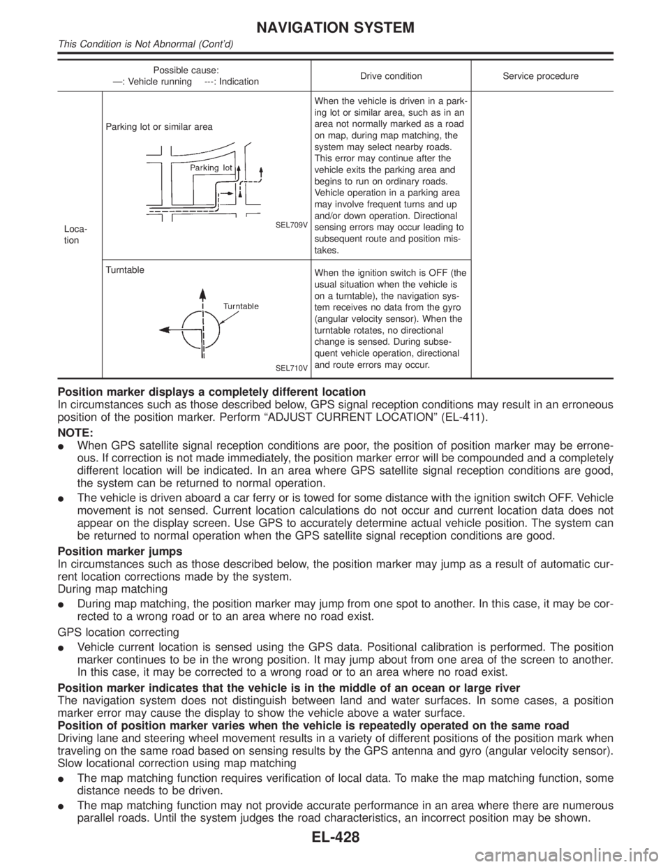
Possible cause:
Ð: Vehicle running ---: IndicationDrive condition Service procedure
Loca-
tionParking lot or similar area
SEL709V
When the vehicle is driven in a park-
ing lot or similar area, such as in an
area not normally marked as a road
on map, during map matching, the
system may select nearby roads.
This error may continue after the
vehicle exits the parking area and
begins to run on ordinary roads.
Vehicle operation in a parking area
may involve frequent turns and up
and/or down operation. Directional
sensing errors may occur leading to
subsequent route and position mis-
takes.
Turntable
SEL710V
When the ignition switch is OFF (the
usual situation when the vehicle is
on a turntable), the navigation sys-
tem receives no data from the gyro
(angular velocity sensor). When the
turntable rotates, no directional
change is sensed. During subse-
quent vehicle operation, directional
and route errors may occur.
Position marker displays a completely different location
In circumstances such as those described below, GPS signal reception conditions may result in an erroneous
position of the position marker. Perform ªADJUST CURRENT LOCATIONº (EL-411).
NOTE:
IWhen GPS satellite signal reception conditions are poor, the position of position marker may be errone-
ous. If correction is not made immediately, the position marker error will be compounded and a completely
different location will be indicated. In an area where GPS satellite signal reception conditions are good,
the system can be returned to normal operation.
IThe vehicle is driven aboard a car ferry or is towed for some distance with the ignition switch OFF. Vehicle
movement is not sensed. Current location calculations do not occur and current location data does not
appear on the display screen. Use GPS to accurately determine actual vehicle position. The system can
be returned to normal operation when the GPS satellite signal reception conditions are good.
Position marker jumps
In circumstances such as those described below, the position marker may jump as a result of automatic cur-
rent location corrections made by the system.
During map matching
IDuring map matching, the position marker may jump from one spot to another. In this case, it may be cor-
rected to a wrong road or to an area where no road exist.
GPS location correcting
IVehicle current location is sensed using the GPS data. Positional calibration is performed. The position
marker continues to be in the wrong position. It may jump about from one area of the screen to another.
In this case, it may be corrected to a wrong road or to an area where no road exist.
Position marker indicates that the vehicle is in the middle of an ocean or large river
The navigation system does not distinguish between land and water surfaces. In some cases, a position
marker error may cause the display to show the vehicle above a water surface.
Position of position marker varies when the vehicle is repeatedly operated on the same road
Driving lane and steering wheel movement results in a variety of different positions of the position mark when
traveling on the same road based on sensing results by the GPS antenna and gyro (angular velocity sensor).
Slow locational correction using map matching
IThe map matching function requires verification of local data. To make the map matching function, some
distance needs to be driven.
IThe map matching function may not provide accurate performance in an area where there are numerous
parallel roads. Until the system judges the road characteristics, an incorrect position may be shown.
NAVIGATION SYSTEM
This Condition is Not Abnormal (Cont'd)
EL-428
Page 1616 of 2395
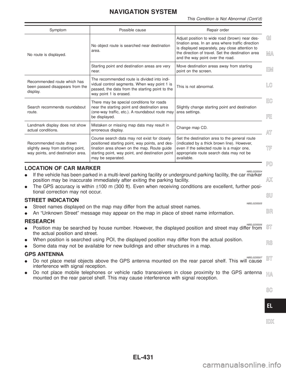
Symptom Possible cause Repair order
No route is displayed.No object route is searched near destination
area.Adjust position to wide road (brown) near des-
tination area. In an area where traffic direction
is displayed separately, pay close attention to
the direction of travel. Set the destination area
and the way point over the road.
Starting point and destination areas are very
near.Move destination areas away from starting
point on the screen.
Recommended route which has
been passed disappears from the
display.The recommended route is divided into indi-
vidual control segments. When way point 1 is
passed, the data from the starting point to the
way point 1 is erased.This is not abnormal.
Search recommends roundabout
route.There may be special conditions for roads
near the starting point and destination area
(one-way traffic, etc.). A roundabout route may
be displayed.Slightly change starting point and destination
area settings.
Landmark display does not show
actual conditions.Mistaken or missing map data may result in
erroneous display.Change map CD.
Recommended route drawn
slightly away from starting point,
way points, and destination area.Course search data may not exist for closely
positioned starting point, way points, and des-
tination area shown on the map. Route guide
starting point, way point, and destination point
may be separated.Set the destination area to the general route
(indicated by a thick brown line). However,
even if the selected route is a major one,
appropriate route search data may not be
available.
LOCATION OF CAR MARKERNBEL0235S04IIf the vehicle has been parked in a multi-level parking facility or underground parking facility, the car marker
position may be inaccurate immediately after exiting the parking facility.
IThe GPS accuracy is within±100 m (300 ft). Even when receiving conditions are excellent, further posi-
tional correction may not occur.
STREET INDICATIONNBEL0235S05IStreet names displayed on the map may differ from the actual street names.
IAn ªUnknown Streetº message may appear on the map in place of street name information.
RESEARCHNBEL0235S06IPosition may be searched by house number. However, the displayed position and street may differ from
the actual position and street.
IWhen position is searched using POI, the displayed position may differ from the actual position.
ISome data may not be available for new buildings and other structures in a map.
GPS ANTENNANBEL0235S07IDo not place metal objects above the GPS antenna mounted on the rear parcel shelf. This will cause
interference with signal reception.
IDo not place mobile telephones or vehicle radio transceivers in close proximity to the GPS antenna
mounted on the rear parcel shelf. This may cause interference with signal reception.
GI
MA
EM
LC
EC
FE
AT
TF
PD
AX
SU
BR
ST
RS
BT
HA
SC
IDX
NAVIGATION SYSTEM
This Condition is Not Abnormal (Cont'd)
EL-431