2001 INFINITI QX4 antenna
[x] Cancel search: antennaPage 1540 of 2395
greatly depending on the cellular network and cellular signal
strength. The system resets to ready when the system com-
pletes the dialing attempts. The vehicle owner can press the
button again if he or she still needs to contact the Communi-
cator Response Center.
IINFINITI Communicator automatically redials if communication
between the vehicle owner and Communicator Response Cen-
ter is lost for some reason.
IThe only way for a transmission to be officially terminated is for
the Communicator Response Center to send an end transmis-
sion signal, which turns off the indicator in the switch. (Com-
munication with Communicator Response Center can not be
terminated by the occupant.)
IIf the vehicle owner start the engine during a call, the conver-
sation may be interrupted. When this happens the system may
try to resume transmission once after the engine has been
started.
SEL526V
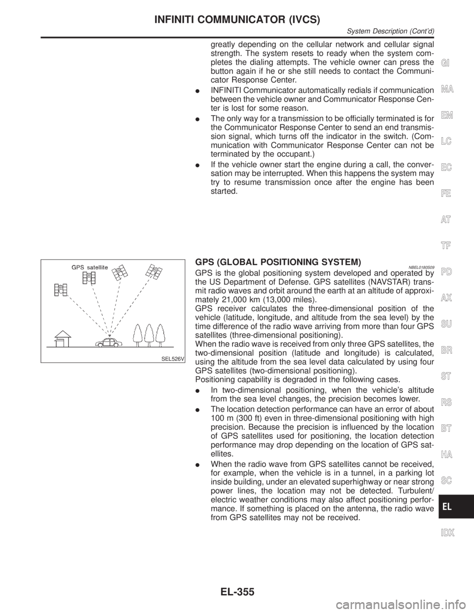
GPS (GLOBAL POSITIONING SYSTEM)NBEL0180S09GPS is the global positioning system developed and operated by
the US Department of Defense. GPS satellites (NAVSTAR) trans-
mit radio waves and orbit around the earth at an altitude of approxi-
mately 21,000 km (13,000 miles).
GPS receiver calculates the three-dimensional position of the
vehicle (latitude, longitude, and altitude from the sea level) by the
time difference of the radio wave arriving from more than four GPS
satellites (three-dimensional positioning).
When the radio wave is received from only three GPS satellites, the
two-dimensional position (latitude and longitude) is calculated,
using the altitude from the sea level data calculated by using four
GPS satellites (two-dimensional positioning).
Positioning capability is degraded in the following cases.
IIn two-dimensional positioning, when the vehicle's altitude
from the sea level changes, the precision becomes lower.
IThe location detection performance can have an error of about
100 m (300 ft) even in three-dimensional positioning with high
precision. Because the precision is influenced by the location
of GPS satellites used for positioning, the location detection
performance may drop depending on the location of GPS sat-
ellites.
IWhen the radio wave from GPS satellites cannot be received,
for example, when the vehicle is in a tunnel, in a parking lot
inside building, under an elevated superhighway or near strong
power lines, the location may not be detected. Turbulent/
electric weather conditions may also affect positioning perfor-
mance. If something is placed on the antenna, the radio wave
from GPS satellites may not be received.
GI
MA
EM
LC
EC
FE
AT
TF
PD
AX
SU
BR
ST
RS
BT
HA
SC
IDX
INFINITI COMMUNICATOR (IVCS)
System Description (Cont'd)
EL-355
Page 1551 of 2395

ªDATA MONITORº MODENBEL0183S04How to Perform Data MonitorNBEL0183S0401
SEL444W
Data Monitor Item ChartNBEL0183S0402
Mode Monitor item Description
GPS MONITORAVAILABLE GPS The number of GPS satellites captured by GPS antenna
DATE Date of Greenwich mean time
GMT TIME Greenwich mean time (Different from local time)
LAT. Latitude
LONG. Longitude
DOPIndex of precision (an index of location status of GPS satellites. The
smaller the value is, the higher the positioning precision is.)
SWITCH MONITORMAYDAY ªMAYDAYº emergency switch condition
INFORMATION ªINFORMATIONº switch condition
DR HANDLE Back door handle switch condition
INFINITI COMMUNICATOR (IVCS)
CONSULT-II (Cont'd)
EL-366
Page 1554 of 2395
SEL532V
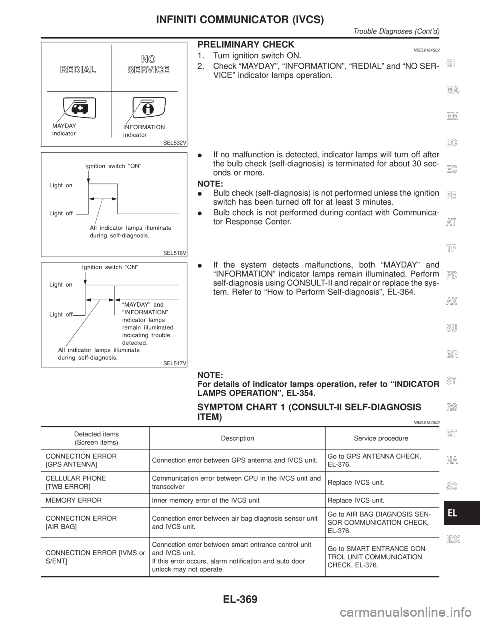
PRELIMINARY CHECKNBEL0184S021. Turn ignition switch ON.
2. Check ªMAYDAYº, ªINFORMATIONº, ªREDIALº and ªNO SER-
VICEº indicator lamps operation.
SEL516V
IIf no malfunction is detected, indicator lamps will turn off after
the bulb check (self-diagnosis) is terminated for about 30 sec-
onds or more.
NOTE:
IBulb check (self-diagnosis) is not performed unless the ignition
switch has been turned off for at least 3 minutes.
IBulb check is not performed during contact with Communica-
tor Response Center.
SEL517V
IIf the system detects malfunctions, both ªMAYDAYº and
ªINFORMATIONº indicator lamps remain illuminated. Perform
self-diagnosis using CONSULT-II and repair or replace the sys-
tem. Refer to ªHow to Perform Self-diagnosisº, EL-364.
NOTE:
For details of indicator lamps operation, refer to ªINDICATOR
LAMPS OPERATIONº, EL-354.
SYMPTOM CHART 1 (CONSULT-II SELF-DIAGNOSIS
ITEM)
NBEL0184S03
Detected items
(Screen items)Description Service procedure
CONNECTION ERROR
[GPS ANTENNA]Connection error between GPS antenna and IVCS unit.Go to GPS ANTENNA CHECK,
EL-376.
CELLULAR PHONE
[TWB ERROR]Communication error between CPU in the IVCS unit and
transceiverReplace IVCS unit.
MEMORY ERROR Inner memory error of the IVCS unit Replace IVCS unit.
CONNECTION ERROR
[AIR BAG]Connection error between air bag diagnosis sensor unit
and IVCS unit.Go to AIR BAG DIAGNOSIS SEN-
SOR COMMUNICATION CHECK,
EL-376.
CONNECTION ERROR [IVMS or
S/ENT]Connection error between smart entrance control unit
and IVCS unit.
If this error occurs, alarm notification and auto door
unlock may not operate.Go to SMART ENTRANCE CON-
TROL UNIT COMMUNICATION
CHECK, EL-376.
GI
MA
EM
LC
EC
FE
AT
TF
PD
AX
SU
BR
ST
RS
BT
HA
SC
IDX
INFINITI COMMUNICATOR (IVCS)
Trouble Diagnoses (Cont'd)
EL-369
Page 1555 of 2395
NOTE:
After replacing IVCS unit, set up the replaced IVCS unit. Refer
to ªSystem Setting (When IVCS Unit is Replaced.)º in EL-381.
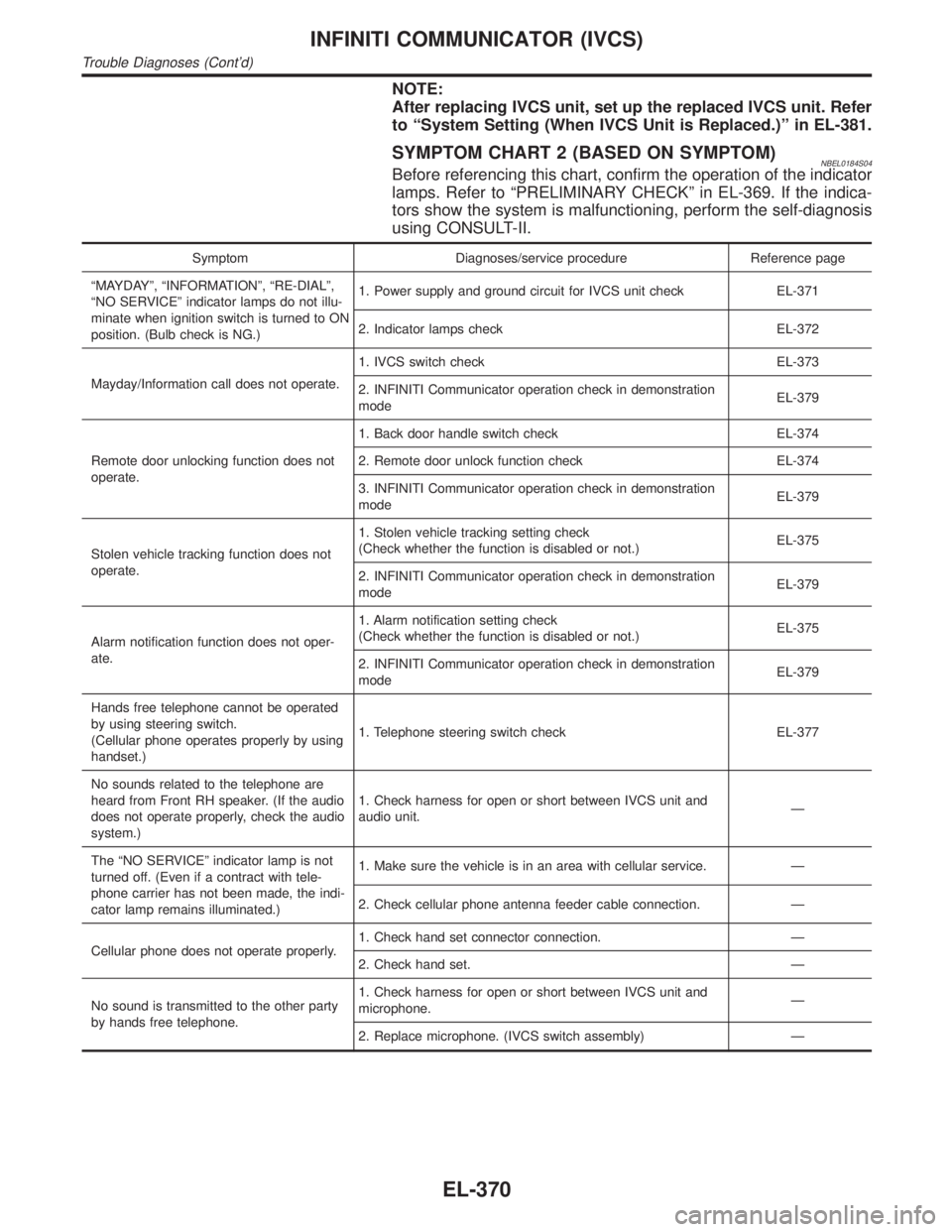
SYMPTOM CHART 2 (BASED ON SYMPTOM)NBEL0184S04Before referencing this chart, confirm the operation of the indicator
lamps. Refer to ªPRELIMINARY CHECKº in EL-369. If the indica-
tors show the system is malfunctioning, perform the self-diagnosis
using CONSULT-II.
Symptom Diagnoses/service procedure Reference page
ªMAYDAYº, ªINFORMATIONº, ªRE-DIALº,
ªNO SERVICEº indicator lamps do not illu-
minate when ignition switch is turned to ON
position. (Bulb check is NG.)1. Power supply and ground circuit for IVCS unit check EL-371
2. Indicator lamps check EL-372
Mayday/Information call does not operate.1. IVCS switch check EL-373
2. INFINITI Communicator operation check in demonstration
modeEL-379
Remote door unlocking function does not
operate.1. Back door handle switch check EL-374
2. Remote door unlock function check EL-374
3. INFINITI Communicator operation check in demonstration
modeEL-379
Stolen vehicle tracking function does not
operate.1. Stolen vehicle tracking setting check
(Check whether the function is disabled or not.)EL-375
2. INFINITI Communicator operation check in demonstration
modeEL-379
Alarm notification function does not oper-
ate.1. Alarm notification setting check
(Check whether the function is disabled or not.)EL-375
2. INFINITI Communicator operation check in demonstration
modeEL-379
Hands free telephone cannot be operated
by using steering switch.
(Cellular phone operates properly by using
handset.)1. Telephone steering switch check EL-377
No sounds related to the telephone are
heard from Front RH speaker. (If the audio
does not operate properly, check the audio
system.)1. Check harness for open or short between IVCS unit and
audio unit.Ð
The ªNO SERVICEº indicator lamp is not
turned off. (Even if a contract with tele-
phone carrier has not been made, the indi-
cator lamp remains illuminated.)1. Make sure the vehicle is in an area with cellular service. Ð
2. Check cellular phone antenna feeder cable connection. Ð
Cellular phone does not operate properly.1. Check hand set connector connection. Ð
2. Check hand set. Ð
No sound is transmitted to the other party
by hands free telephone.1. Check harness for open or short between IVCS unit and
microphone.Ð
2. Replace microphone. (IVCS switch assembly) Ð
INFINITI COMMUNICATOR (IVCS)
Trouble Diagnoses (Cont'd)
EL-370
Page 1561 of 2395

GPS ANTENNA CHECK=NBEL0184S11
1 CHECK VOLTAGE FOR GPS ANTENNA
1. Disconnect GPS feeder cable connector from IVCS unit.
2. Turn ignition switch ON.
3. Check voltage at IVCS unit GPS feeder cable terminal.
SEL106W
Does approx. 5V exist?
Ye s©Replace GPS antenna.
No©Replace IVCS unit.
AIR BAG DIAGNOSES SENSOR UNIT
COMMUNICATION CHECK
NBEL0184S12
1 AIR BAG OPERATION CHECK
Turn ignition switch ON and check air bag warning lamp operation. (For details, refer to RS-38.)
Does air bag warning lamp operate properly?
Ye s©Check harness connector connection between air bag diagnosis sensor unit and IVCS
unit.
No©Check supplemental restraint system. Refer to RS-29.
SMART ENTRANCE CONTROL UNIT COMMUNICATION
CHECK
NBEL0184S13
1 CHECK SMART ENTRANCE CONTROL UNIT OPERATION
Check the system related smart entrance control unit operation. (e.g.: power door lock, power window)
Does the system operate properly?
Ye s©Check harness for open or short between smart entrance control unit and IVCS unit.
No©Check smart entrance control unit. Refer to ªSMART ENTRANCE CONTROL UNITº in
the Service Manual. (EL-324)
INFINITI COMMUNICATOR (IVCS)
Trouble Diagnoses (Cont'd)
EL-376
Page 1565 of 2395
SEL528V
4. Touch ªBACKº key of CONSULT-II until ªSELECT SYSTEMº
appears, then turn off CONSULT-II.
5. Turn ignition switch to the OFF position.
6. Disconnect CONSULT-II DDL connector.
7. Start the engine.
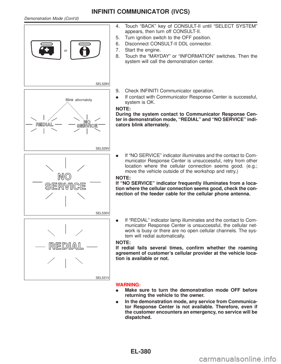
8. Touch the ªMAYDAYº or ªINFORMATIONº switches. Then the
system will call the demonstration center.
SEL529V
9. Check INFINITI Communicator operation.
IIf contact with Communicator Response Center is successful,
system is OK.
NOTE:
During the system contact to Communicator Response Cen-
ter in demonstration mode, ªREDIALº and ªNO SERVICEº indi-
cators blink alternately.
SEL530V
IIf ªNO SERVICEº indicator illuminates and the contact to Com-
municator Response Center is unsuccessful, retry from other
location where the cellular connection seems good. (e.g.;
move the vehicle outside of the workshop and retry.)
NOTE:
If ªNO SERVICEº indicator frequently illuminates from a loca-
tion where the cellular connection seems good, check the con-
nection of the feeder cable for the cellular phone antenna.
SEL531V
IIf ªREDIALº indicator lamp illuminates and the contact to Com-
municator Response Center is unsuccessful, the cellular net-
work is busy or there are no open cellular channels. The sys-
tem will redial automatically.
NOTE:
If redial fails several times, confirm whether the roaming
agreement of customer's cellular provider at the vehicle loca-
tion is available or not.
WARNING:
IMake sure to turn the demonstration mode OFF before
returning the vehicle to the owner.
IIn the demonstration mode, any service from Communica-
tor Response Center is not available. Therefore, even if
the customer encounters an emergency, no service will be
dispatched.
INFINITI COMMUNICATOR (IVCS)
Demonstration Mode (Cont'd)
EL-380
Page 1571 of 2395
SEL683V
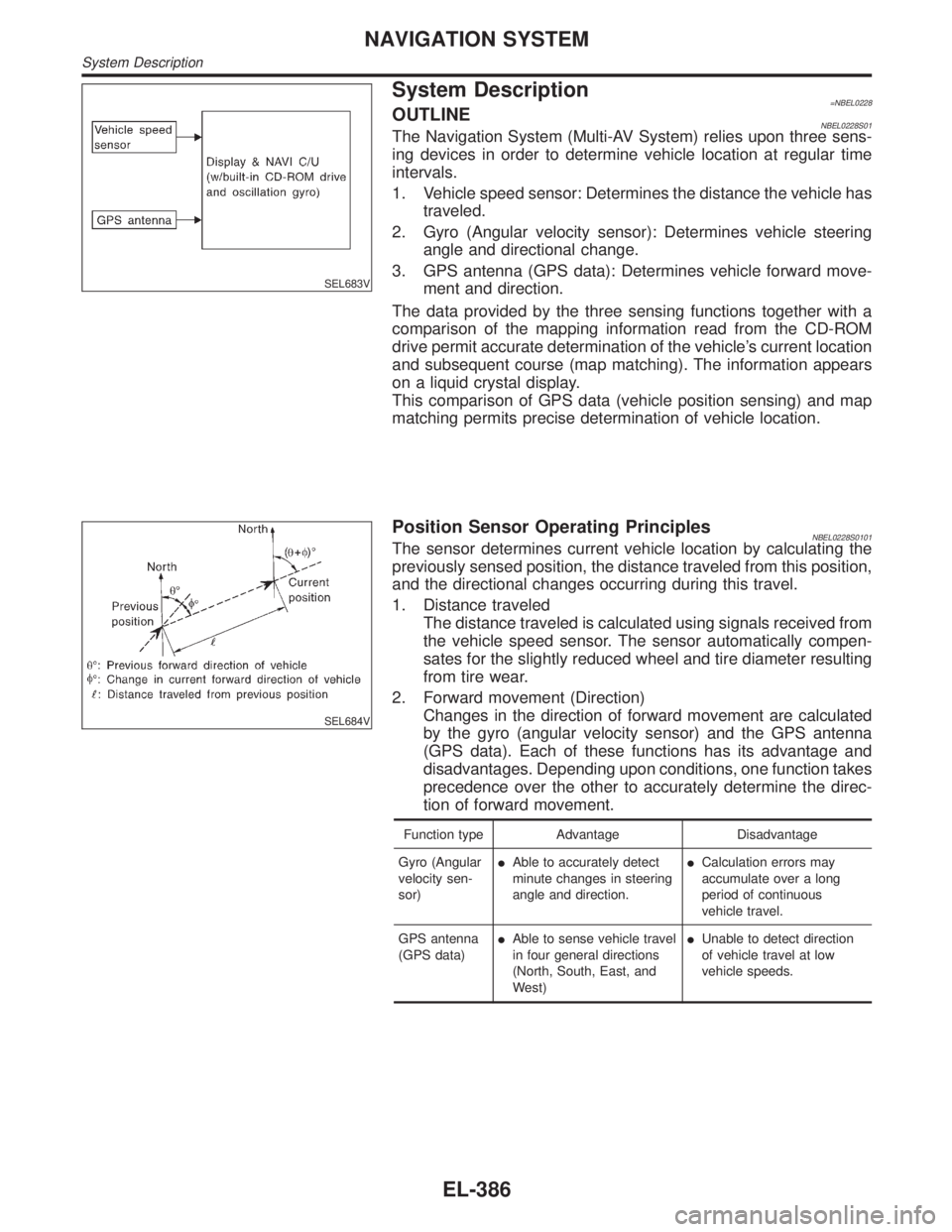
System Description=NBEL0228OUTLINENBEL0228S01The Navigation System (Multi-AV System) relies upon three sens-
ing devices in order to determine vehicle location at regular time
intervals.
1. Vehicle speed sensor: Determines the distance the vehicle has
traveled.
2. Gyro (Angular velocity sensor): Determines vehicle steering
angle and directional change.
3. GPS antenna (GPS data): Determines vehicle forward move-
ment and direction.
The data provided by the three sensing functions together with a
comparison of the mapping information read from the CD-ROM
drive permit accurate determination of the vehicle's current location
and subsequent course (map matching). The information appears
on a liquid crystal display.
This comparison of GPS data (vehicle position sensing) and map
matching permits precise determination of vehicle location.
SEL684V
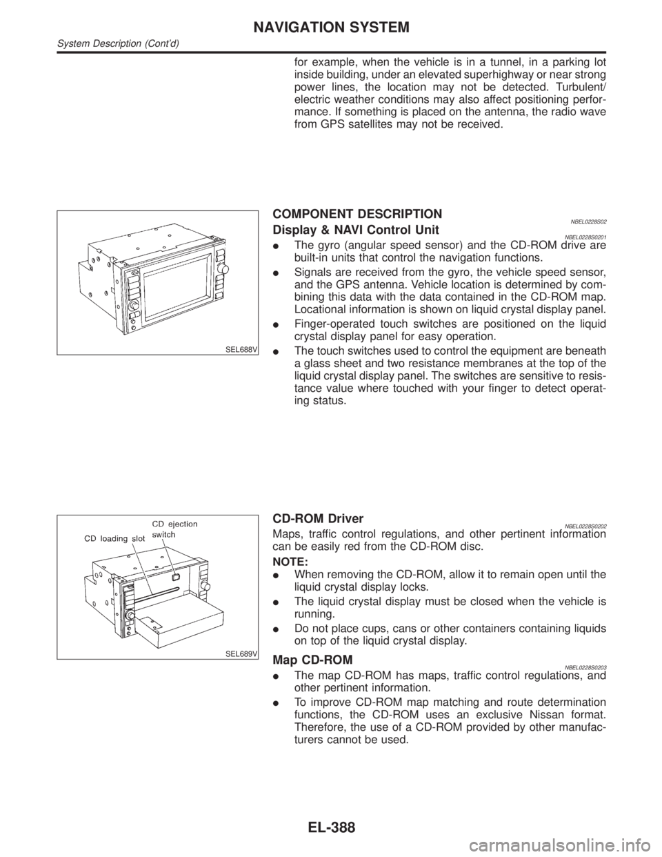
Position Sensor Operating PrinciplesNBEL0228S0101The sensor determines current vehicle location by calculating the
previously sensed position, the distance traveled from this position,
and the directional changes occurring during this travel.
1. Distance traveled
The distance traveled is calculated using signals received from
the vehicle speed sensor. The sensor automatically compen-
sates for the slightly reduced wheel and tire diameter resulting
from tire wear.
2. Forward movement (Direction)
Changes in the direction of forward movement are calculated
by the gyro (angular velocity sensor) and the GPS antenna
(GPS data). Each of these functions has its advantage and
disadvantages. Depending upon conditions, one function takes
precedence over the other to accurately determine the direc-
tion of forward movement.
Function type Advantage Disadvantage
Gyro (Angular
velocity sen-
sor)IAble to accurately detect
minute changes in steering
angle and direction.ICalculation errors may
accumulate over a long
period of continuous
vehicle travel.
GPS antenna
(GPS data)IAble to sense vehicle travel
in four general directions
(North, South, East, and
West)IUnable to detect direction
of vehicle travel at low
vehicle speeds.
NAVIGATION SYSTEM
System Description
EL-386
Page 1573 of 2395
for example, when the vehicle is in a tunnel, in a parking lot
inside building, under an elevated superhighway or near strong
power lines, the location may not be detected. Turbulent/
electric weather conditions may also affect positioning perfor-
mance. If something is placed on the antenna, the radio wave
from GPS satellites may not be received.
SEL688V
COMPONENT DESCRIPTIONNBEL0228S02Display & NAVI Control UnitNBEL0228S0201IThe gyro (angular speed sensor) and the CD-ROM drive are
built-in units that control the navigation functions.
ISignals are received from the gyro, the vehicle speed sensor,
and the GPS antenna. Vehicle location is determined by com-
bining this data with the data contained in the CD-ROM map.
Locational information is shown on liquid crystal display panel.
IFinger-operated touch switches are positioned on the liquid
crystal display panel for easy operation.
IThe touch switches used to control the equipment are beneath
a glass sheet and two resistance membranes at the top of the
liquid crystal display panel. The switches are sensitive to resis-
tance value where touched with your finger to detect operat-
ing status.
SEL689V
CD-ROM DriverNBEL0228S0202Maps, traffic control regulations, and other pertinent information
can be easily red from the CD-ROM disc.
NOTE:
IWhen removing the CD-ROM, allow it to remain open until the
liquid crystal display locks.
IThe liquid crystal display must be closed when the vehicle is
running.
IDo not place cups, cans or other containers containing liquids
on top of the liquid crystal display.
Map CD-ROMNBEL0228S0203IThe map CD-ROM has maps, traffic control regulations, and
other pertinent information.
ITo improve CD-ROM map matching and route determination
functions, the CD-ROM uses an exclusive Nissan format.
Therefore, the use of a CD-ROM provided by other manufac-
turers cannot be used.
NAVIGATION SYSTEM
System Description (Cont'd)
EL-388