2001 INFINITI QX4 warning light
[x] Cancel search: warning lightPage 1187 of 2395
Electrical Components Inspection ...........................108
COMPASS AND THERMOMETER............................. 110
System Description .................................................. 110
Wiring Diagram - COMPAS -................................... 111
Trouble Diagnoses................................................... 112
Calibration Procedure for Compass ........................ 113
WARNING LAMPS...................................................... 114
Schematic ................................................................ 114
Wiring Diagram - WARN - ....................................... 115
Fuel Warning Lamp Sensor Check .........................122
Electrical Components Inspection ...........................122
A/T INDICATOR...........................................................123
Wiring Diagram - AT/IND -.......................................123
WARNING CHIME.......................................................125
Component Parts and Harness Connector
Location ...................................................................125
System Description ..................................................125
Wiring Diagram - CHIME - ......................................127
Trouble Diagnoses...................................................129
FRONT WIPER AND WASHER..................................136
System Description ..................................................136
Wiring Diagram - WIPER - ......................................138
Removal and Installation .........................................139
Washer Nozzle Adjustment .....................................140
Washer Tube Layout ...............................................140
REAR WIPER AND WASHER....................................141
System Description ..................................................141
Wiring Diagram - WIP/R -........................................143
Trouble Diagnoses...................................................145
Removal and Installation .........................................145
Washer Nozzle Adjustment .....................................146
Washer Tube Layout ...............................................146
Check Valve .............................................................146
HORN...........................................................................147
Wiring Diagram - HORN - .......................................147
CIGARETTE LIGHTER................................................148
Wiring Diagram - CIGAR -.......................................148
CLOCK.........................................................................150
Wiring Diagram - CLOCK -......................................150
REAR WINDOW DEFOGGER.....................................151
Component Parts and Harness Connector
Location ...................................................................151
System Description ..................................................151
Wiring Diagram - DEF - ...........................................153
Trouble Diagnoses...................................................155
Electrical Components Inspection ...........................157
Filament Check ........................................................157
Filament Repair .......................................................158
AUDIO..........................................................................160
System Description ..................................................160
Schematic ................................................................161
Wiring Diagram - AUDIO - .......................................162Trouble Diagnoses...................................................166
Inspection.................................................................167
Wiring Diagram - REMOTE -...................................168
AUDIO ANTENNA.......................................................169
System Description ..................................................169
Wiring Diagram - P/ANT - .......................................170
Trouble Diagnoses...................................................171
Location of Antenna .................................................171
Antenna Rod Replacement .....................................171
POWER SUNROOF.....................................................173
System Description ..................................................173
Wiring Diagram - SROOF - .....................................174
Trouble Diagnoses...................................................176
DOOR MIRROR...........................................................177
Wiring Diagram - MIRROR - ...................................177
GLASS HATCH OPENER...........................................178
System Description ..................................................178
Wiring Diagram - TLID - ..........................................179
FUEL FILLER LID OPENER.......................................180
Wiring Diagram - F/LID - .........................................180
POWER SEAT.............................................................181
Wiring Diagram - SEAT - .........................................181
HEATED SEAT............................................................183
Wiring Diagram - HSEAT - ......................................183
Seatback Heating Unit .............................................185
AUTOMATIC DRIVE POSITIONER............................186
Component Parts and Harness Connector
Location ...................................................................186
System Description ..................................................187
Schematic ................................................................190
Wiring Diagram - AUT/DP - .....................................191
On Board Diagnosis ................................................196
Trouble Diagnoses...................................................198
AUTOMATIC SPEED CONTROL DEVICE (ASCD)...221
Component Parts and Harness Connector
Location ...................................................................221
System Description ..................................................222
Schematic ................................................................224
Wiring Diagram - ASCD - ........................................225
Fail-safe System ......................................................229
Trouble Diagnoses...................................................230
Electrical Component Inspection .............................239
ASCD Wire Adjustment ...........................................240
POWER WINDOW.......................................................241
System Description ..................................................241
Schematic ................................................................244
Wiring Diagram - WINDOW - ..................................245
Trouble Diagnoses...................................................250
POWER DOOR LOCK.................................................254
Component Parts and Harness Connector
Location ...................................................................254
System Description ..................................................254
CONTENTS(Cont'd)
EL-2
Page 1218 of 2395

Ito headlamp battery saver control unit terminals 5 and 13 from lighting switch terminal 11, and
Ito headlamp LH and RH relays terminal 2 from headlamp battery saver control unit terminals 2 and 8
Ithrough headlamp battery saver control unit terminals 3 and 9, and
Ithrough lighting switch terminal 12.
Then headlamps illuminate again.
AUTO LIGHT OPERATIONNBEL0188S05When lighting switch is in ªAUTOº position, ground is supplied
Ito auto light control unit terminal 10
Ifrom lighting switch terminal 42.
When ignition switch is turn to ªONº or ªSTARTº position and outside brightness is darker than prescribed level.
Ground is supplied
Ito headlamp relay LH and RH terminals 2
Ithrough battery saver control unit
Ifrom auto light control unit terminal 6, and
Ito tail lamp relay terminal 1
Ithrough battery saver control unit
Ifrom auto light control unit terminal 7.
Then both headlamp relays and tail lamp relay are energized, headlamps (low or high) and tail lamps are illu-
minate according to switch position.
Auto light operation allows headlamps and tail lamps to go off when
IIgnition switch is turned to ªOFFº position or
IOutside brightness is brighter than prescribed level.
NOTE:
The delay time is varies up to maximum of 20 seconds as the outside brightness changes.
For parking, license and tail lamp auto operation, refer to ªPARKING, LICENSE AND TAIL LAMPSº.
THEFT WARNING SYSTEMNBEL0188S06The theft warning system will flash the low beams if the system is triggered. Refer to ªTHEFT WARNING
SYSTEMº (EL-296).
GI
MA
EM
LC
EC
FE
AT
TF
PD
AX
SU
BR
ST
RS
BT
HA
SC
IDX
HEADLAMP (FOR USA) Ð XENON TYPE Ð
System Description (Cont'd)
EL-33
Page 1225 of 2395
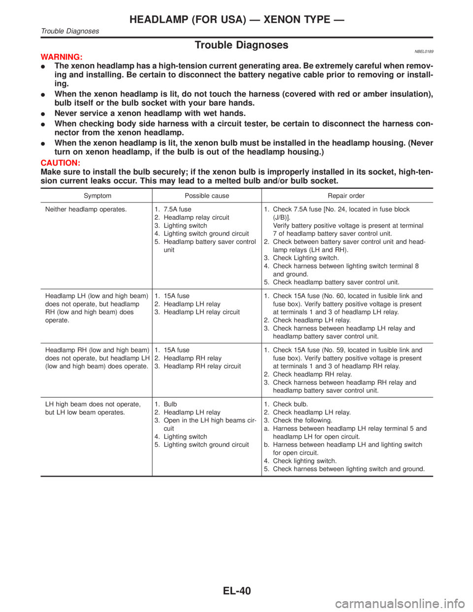
Trouble DiagnosesNBEL0189WARNING:
IThe xenon headlamp has a high-tension current generating area. Be extremely careful when remov-
ing and installing. Be certain to disconnect the battery negative cable prior to removing or install-
ing.
IWhen the xenon headlamp is lit, do not touch the harness (covered with red or amber insulation),
bulb itself or the bulb socket with your bare hands.
INever service a xenon headlamp with wet hands.
IWhen checking body side harness with a circuit tester, be certain to disconnect the harness con-
nector from the xenon headlamp.
IWhen the xenon headlamp is lit, the xenon bulb must be installed in the headlamp housing. (Never
turn on xenon headlamp, if the bulb is out of the headlamp housing.)
CAUTION:
Make sure to install the bulb securely; if the xenon bulb is improperly installed in its socket, high-ten-
sion current leaks occur. This may lead to a melted bulb and/or bulb socket.
Symptom Possible cause Repair order
Neither headlamp operates. 1. 7.5A fuse
2. Headlamp relay circuit
3. Lighting switch
4. Lighting switch ground circuit
5. Headlamp battery saver control
unit1. Check 7.5A fuse [No. 24, located in fuse block
(J/B)].
Verify battery positive voltage is present at terminal
7 of headlamp battery saver control unit.
2. Check between battery saver control unit and head-
lamp relays (LH and RH).
3. Check Lighting switch.
4. Check harness between lighting switch terminal 8
and ground.
5. Check headlamp battery saver control unit.
Headlamp LH (low and high beam)
does not operate, but headlamp
RH (low and high beam) does
operate.1. 15A fuse
2. Headlamp LH relay
3. Headlamp LH relay circuit1. Check 15A fuse (No. 60, located in fusible link and
fuse box). Verify battery positive voltage is present
at terminals 1 and 3 of headlamp LH relay.
2. Check headlamp LH relay.
3. Check harness between headlamp LH relay and
headlamp battery saver control unit.
Headlamp RH (low and high beam)
does not operate, but headlamp LH
(low and high beam) does operate.1. 15A fuse
2. Headlamp RH relay
3. Headlamp RH relay circuit1. Check 15A fuse (No. 59, located in fusible link and
fuse box). Verify battery positive voltage is present
at terminals 1 and 3 of headlamp RH relay.
2. Check headlamp RH relay.
3. Check harness between headlamp RH relay and
headlamp battery saver control unit.
LH high beam does not operate,
but LH low beam operates.1. Bulb
2. Headlamp LH relay
3. Open in the LH high beams cir-
cuit
4. Lighting switch
5. Lighting switch ground circuit1. Check bulb.
2. Check headlamp LH relay.
3. Check the following.
a. Harness between headlamp LH relay terminal 5 and
headlamp LH for open circuit.
b. Harness between headlamp LH and lighting switch
for open circuit.
4. Check lighting switch.
5. Check harness between lighting switch and ground.
HEADLAMP (FOR USA) Ð XENON TYPE Ð
Trouble Diagnoses
EL-40
Page 1228 of 2395
Terminal No.Wire
colorItem ConditionVoltage
(Approximate value)
10 R/Y RAP signal Ignition switch OFF or ACC
(After more than 45 seconds with ignition
switch turned OFF or ACC)Less than 1V
ON or START Battery voltage
11 B Ground Ð Ð
13 G Tail lamp switch Lighting switch OFF Battery voltage
1ST or 2ND Less than 1V
14 R Tail lamp relay Ignition switch
(with lighting switch
1ST or 2ND)OFF or ACC More than 45 sec-
onds after ignition
switch is turned
OFF or ACCBattery voltage
Within 45 seconds
after ignition switch
is turned OFF or
ACCLess than 1V
ON or START Less than 1V
Headlamps illuminate by auto light control. Less than 1V
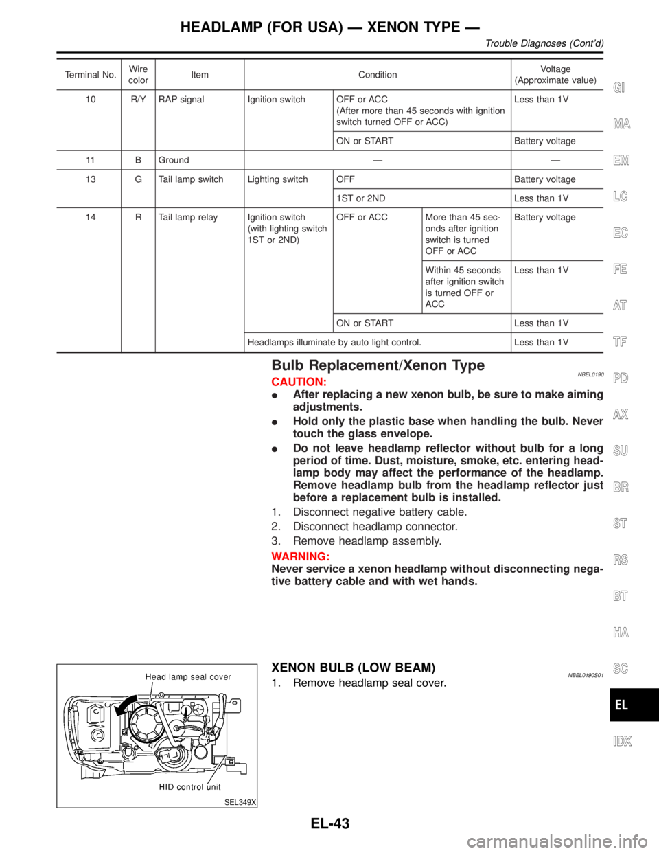
Bulb Replacement/Xenon TypeNBEL0190CAUTION:
IAfter replacing a new xenon bulb, be sure to make aiming
adjustments.
IHold only the plastic base when handling the bulb. Never
touch the glass envelope.
IDo not leave headlamp reflector without bulb for a long
period of time. Dust, moisture, smoke, etc. entering head-
lamp body may affect the performance of the headlamp.
Remove headlamp bulb from the headlamp reflector just
before a replacement bulb is installed.
1. Disconnect negative battery cable.
2. Disconnect headlamp connector.
3. Remove headlamp assembly.
WARNING:
Never service a xenon headlamp without disconnecting nega-
tive battery cable and with wet hands.
SEL349X
XENON BULB (LOW BEAM)NBEL0190S011. Remove headlamp seal cover.
GI
MA
EM
LC
EC
FE
AT
TF
PD
AX
SU
BR
ST
RS
BT
HA
SC
IDX
HEADLAMP (FOR USA) Ð XENON TYPE Ð
Trouble Diagnoses (Cont'd)
EL-43
Page 1310 of 2395

Component Parts and Harness Connector
Location
NBEL0052
SEL046W
System DescriptionNBEL0053The warning chime is controlled by the smart entrance control unit.
The warning chime is located in the smart entrance control unit.
Power is supplied at all times
Ithrough 7.5A fuse [No. 24, located in the fuse block (J/B)]
Ito smart entrance control unit terminal 10, and
Ito key switch terminal 2, and
Ithrough 10A fuse [No. 61, located in the fuse block (J/B)]
Ito tail lamp relay terminals 2 and 3.
With the ignition switch in the ON or START position, power is supplied
Ithrough 7.5A fuse [No. 11, located in the fuse block (J/B)]
Ito smart entrance control unit terminal 33.
Ground is supplied to smart entrance control unit terminal 16 through body grounds M77 and M111.
IGNITION KEY WARNING CHIMENBEL0053S01With the key in the ignition switch in the OFF or ACC position, and the driver's door open, the warning chime
will sound. Power is supplied
Ifrom key switch terminal 1
Ito smart entrance control unit terminal 32.
Ground is supplied
Ifrom front door switch LH terminal 1
Ito smart entrance control unit terminal 29.
Front door switch LH terminal 2 is grounded through body grounds B11, B22 and D210.
LIGHT WARNING CHIMENBEL0053S02With ignition switch OFF or ACC, driver's door open, warning chime will sound. [Except when headlamp bat-
tery saver control operates (for 45 seconds after ignition switch is turned to OFF or ACC position) and head-
lamps do not illuminate.] Power is supplied.
Ifrom tail lamp relay terminal 5
Ito smart entrance control unit terminal 34.
Ground is supplied
Ifrom front door switch LH terminal 1
GI
MA
EM
LC
EC
FE
AT
TF
PD
AX
SU
BR
ST
RS
BT
HA
SC
IDX
WARNING CHIME
Component Parts and Harness Connector Location
EL-125
Page 1314 of 2395
Trouble DiagnosesNBEL0055SYMPTOM CHARTNBEL0055S01
REFERENCE PAGE (EL- ) 129 131 133 134 135
SYMPTOM
POWER SUPPLY AND GROUND CIRCUIT CHECK
LIGHTING SWITCH INPUT SIGNAL CHECK
KEY SWITCH (INSERT) CHECK
SEAT BELT BUCKLE SWITCH CHECK
DRIVER SIDE DOOR SWITCH CHECK
Light warning chime does not acti-
vate.XX X
Ignition key warning chime does not
activate.XXX
Seat belt warning chime does not
activate.XX
All warning chimes do not activate. X
SEL301X
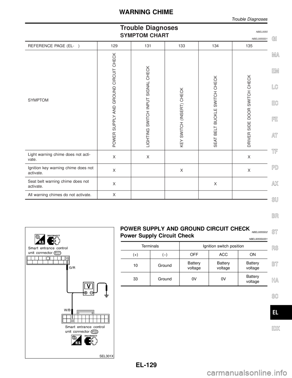
POWER SUPPLY AND GROUND CIRCUIT CHECKNBEL0055S02Power Supply Circuit CheckNBEL0055S0201
Terminals Ignition switch position
(+) (þ) OFF ACC ON
10 GroundBattery
voltageBattery
voltageBattery
voltage
33 Ground 0V 0VBattery
voltage
GI
MA
EM
LC
EC
FE
AT
TF
PD
AX
SU
BR
ST
RS
BT
HA
SC
IDX
WARNING CHIME
Trouble Diagnoses
EL-129
Page 1316 of 2395
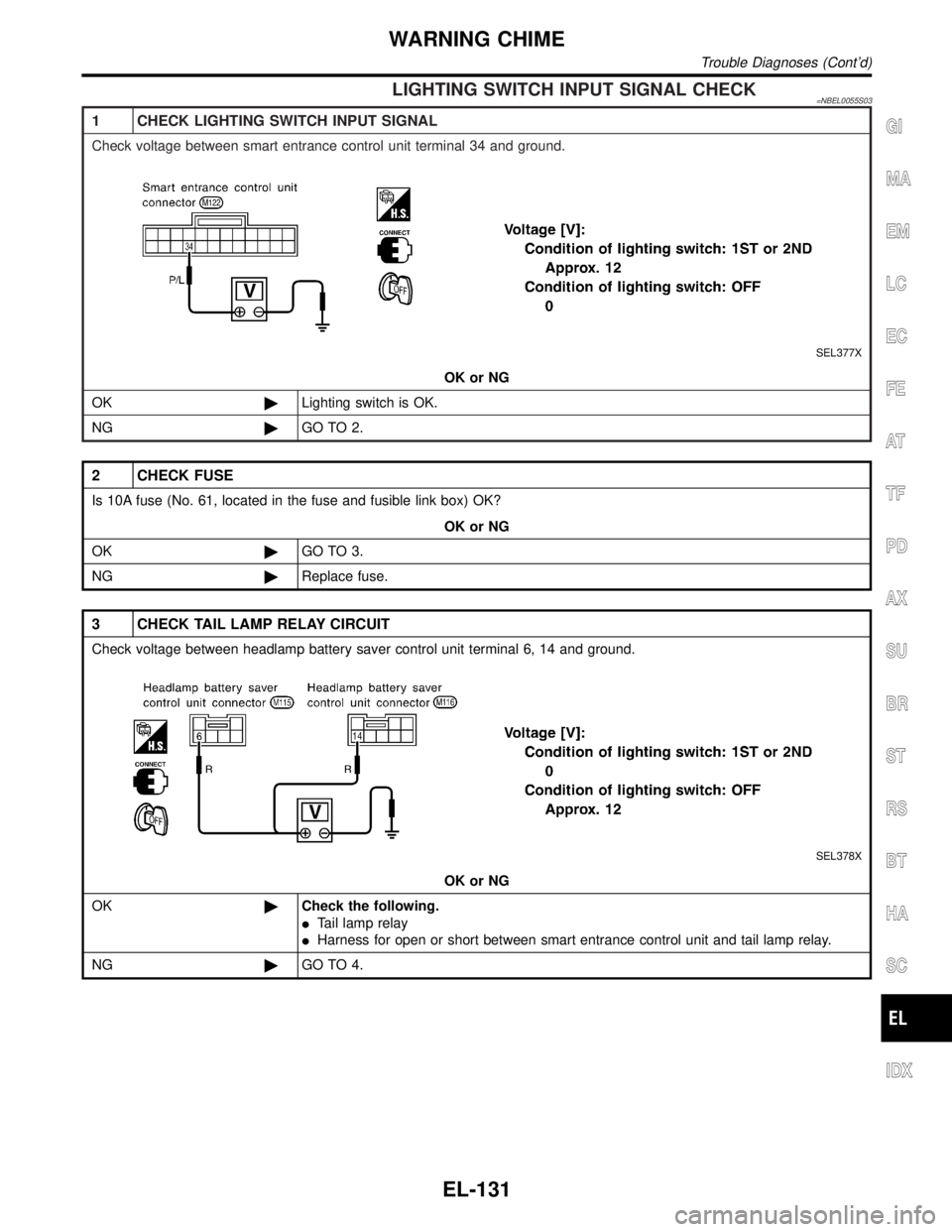
LIGHTING SWITCH INPUT SIGNAL CHECK=NBEL0055S03
1 CHECK LIGHTING SWITCH INPUT SIGNAL
Check voltage between smart entrance control unit terminal 34 and ground.
SEL377X
OK or NG
OK©Lighting switch is OK.
NG©GO TO 2.
2 CHECK FUSE
Is 10A fuse (No. 61, located in the fuse and fusible link box) OK?
OK or NG
OK©GO TO 3.
NG©Replace fuse.
3 CHECK TAIL LAMP RELAY CIRCUIT
Check voltage between headlamp battery saver control unit terminal 6, 14 and ground.
SEL378X
OK or NG
OK©Check the following.
ITail lamp relay
IHarness for open or short between smart entrance control unit and tail lamp relay.
NG©GO TO 4.
GI
MA
EM
LC
EC
FE
AT
TF
PD
AX
SU
BR
ST
RS
BT
HA
SC
IDX
WARNING CHIME
Trouble Diagnoses (Cont'd)
EL-131
Page 1317 of 2395
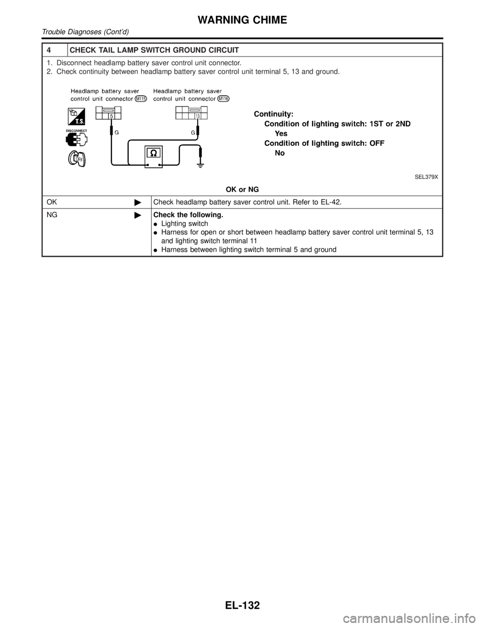
4 CHECK TAIL LAMP SWITCH GROUND CIRCUIT
1. Disconnect headlamp battery saver control unit connector.
2. Check continuity between headlamp battery saver control unit terminal 5, 13 and ground.
SEL379X
OK or NG
OK©Check headlamp battery saver control unit. Refer to EL-42.
NG©Check the following.
ILighting switch
IHarness for open or short between headlamp battery saver control unit terminal 5, 13
and lighting switch terminal 11
IHarness between lighting switch terminal 5 and ground
WARNING CHIME
Trouble Diagnoses (Cont'd)
EL-132