Page 1978 of 2395
SEM164F
AEM080
Precautions
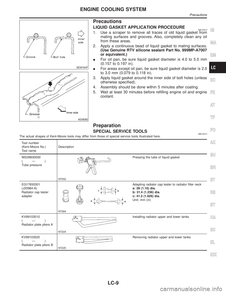
LIQUID GASKET APPLICATION PROCEDURENBLC00131. Use a scraper to remove all traces of old liquid gasket from
mating surfaces and grooves. Also, completely clean any oil
from these areas.
2. Apply a continuous bead of liquid gasket to mating surfaces.
(Use Genuine RTV silicone sealant Part No. 999MP-A7007
or equivalent.)
IFor oil pan, be sure liquid gasket diameter is 4.0 to 5.0 mm
(0.157 to 0.197 in).
IFor areas except oil pan, be sure liquid gasket diameter is 2.0
to 3.0 mm (0.079 to 0.118 in).
3. Apply liquid gasket around the inner side of bolt holes (unless
otherwise specified).
4. Assembly should be done within 5 minutes after coating.
5. Wait at least 30 minutes before refilling engine oil and engine
coolant.
Preparation
SPECIAL SERVICE TOOLSNBLC0014The actual shapes of Kent-Moore tools may differ from those of special service tools illustrated here.
Tool number
(Kent-Moore No.)
Tool nameDescription
WS39930000
(Ð)
Tube pressure
NT052
Pressing the tube of liquid gasket
EG17650301
(J33984-A)
Radiator cap tester
adapter
NT564
Adapting radiator cap tester to radiator filler neck
a: 28 (1.10) dia.
b: 31.4 (1.236) dia.
c: 41.3 (1.626) dia.
Unit: mm (in)
KV99103510
(Ð)
Radiator plate pliers A
NT224
Installing radiator upper and lower tanks
KV99103520
(Ð)
Radiator plate pliers B
NT225
Removing radiator upper and lower tanks
GI
MA
EM
EC
FE
AT
TF
PD
AX
SU
BR
ST
RS
BT
HA
SC
EL
IDX
ENGINE COOLING SYSTEM
Precautions
LC-9
Page 1980 of 2395
System CheckNBLC0016WARNING:
Never remove the radiator cap when the engine is hot; serious
burns could be caused by high pressure fluid escaping from
the radiator.
Wrap a thick cloth around the cap and carefully remove it by
turning it a quarter turn to allow built-up pressure to escape
and then turn the cap all the way off.
CHECKING COOLING SYSTEM HOSESNBLC0016S01Check hoses for improper attachment, leaks, cracks, damage,
loose connections, chafing and deterioration.
CHECKING RADIATORNBLC0016S02Check radiator for mud or clogging. If necessary, clean radiator as
follows.
IBe careful not to bend or damage the radiator fins.
IWhen radiator is cleaned without removal, remove all sur-
rounding parts such as cooling fan, radiator shroud and horns.
Then tape the harness and connectors to prevent water from
entering.
1. Apply water by hose to the back side of the radiator core ver-
tically downward.
2. Apply water again to all radiator core surfaces once per
minute.
3. Stop washing if any stains no longer flow out from the radia-
tor.
4. Blow air into the back side of radiator core vertically downward.
IUse compressed air lower than 490 kPa (5 kg/cm
2, 71 psi) and
keep distance more than 30 cm (11.8 in).
5. Blow air again into all the radiator core surfaces once per
minute until no water sprays out.
SLC755A
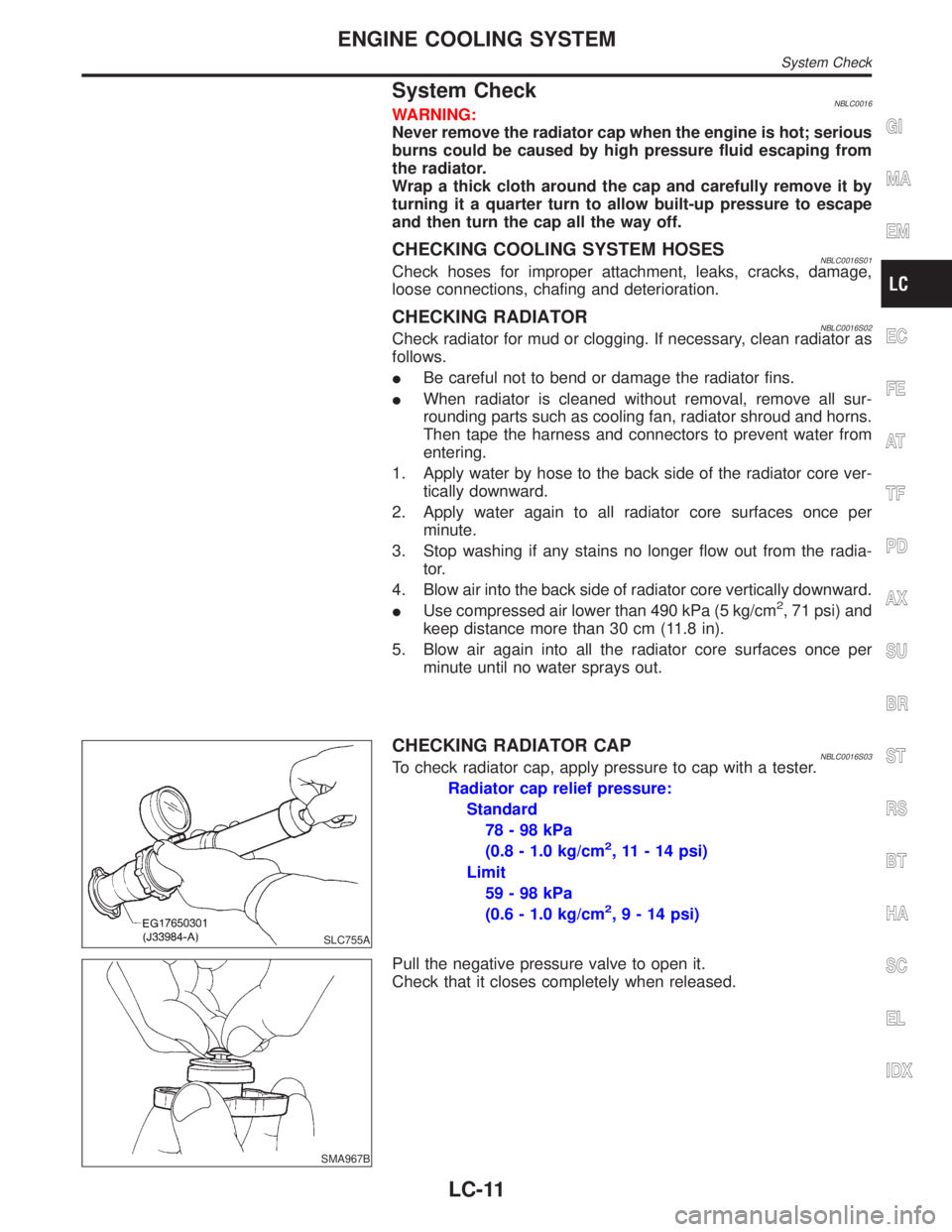
CHECKING RADIATOR CAPNBLC0016S03To check radiator cap, apply pressure to cap with a tester.
Radiator cap relief pressure:
Standard
78-98kPa
(0.8 - 1.0 kg/cm
2, 11 - 14 psi)
Limit
59-98kPa
(0.6 - 1.0 kg/cm
2,9-14psi)
SMA967B
Pull the negative pressure valve to open it.
Check that it closes completely when released.
GI
MA
EM
EC
FE
AT
TF
PD
AX
SU
BR
ST
RS
BT
HA
SC
EL
IDX
ENGINE COOLING SYSTEM
System Check
LC-11
Page 1981 of 2395
SLC756A
CHECKING COOLING SYSTEM FOR LEAKSNBLC0016S04To check for leakage, apply pressure to the cooling system with a
tester.
Testing pressure:
157 kPa (1.6 kg/cm
2, 23 psi)
CAUTION:
Higher than the specified pressure may cause radiator
damage.
Water Pump
REMOVAL AND INSTALLATIONNBLC0017CAUTION:
IWhen removing water pump assembly, be careful not to
get coolant on drive belt.
IWater pump cannot be disassembled and should be
replaced as a unit.
IAfter installing water pump, connect hose and clamp
securely, then check for leaks using radiator cap tester.
SLC326B
SLC327B
REMOVALNBLC00181. Remove under cover.
2. Remove suspension member stay.
3. Drain coolant from radiator.
4. Remove radiator shrouds.
5. Remove drive belts.
6. Remove cooling fan.
7. Remove water drain plug on water pump side of cylinder block.
8. Remove chain tensioner cover and water pump cover.
ENGINE COOLING SYSTEM
System Check (Cont'd)
LC-12
Page 1993 of 2395
Overheating Cause AnalysisNBLC0029
Symptom Check items
Cooling sys-
tem parts
malfunctionPoor heat transferWater pump malfunction Worn or loose drive belt
Ð Thermostat stuck closed Ð
Damaged finsDust contamination or
paper clogging
Mechanical damage
Clogged radiator cooling
tubeExcess foreign material
(rust, dirt, sand, etc.)
Reduced air flowCooling fan does not oper-
ate
ÐÐ High resistance to fan rota-
tion
Damaged fan blades
Damaged radiator shroud Ð Ð Ð
Improper coolant mixture
ratioÐÐÐ
Poor coolant quality Ð Ð Ð
Insufficient coolantCoolant leaksCooling hoseLoose clamp
Cracked hose
Water pump Poor sealing
Radiator capLoose
Poor sealing
RadiatorO-ring for damage, dete-
rioration or improper fit-
ting
Cracked radiator tank
Cracked radiator core
Reservoir tank Cracked reservoir tank
Overflowing reservoir tankExhaust gas leaks into
cooling systemCylinder head deteriora-
tion
Cylinder head gasket
deterioration
ENGINE COOLING SYSTEM
Overheating Cause Analysis
LC-24
Page 1994 of 2395
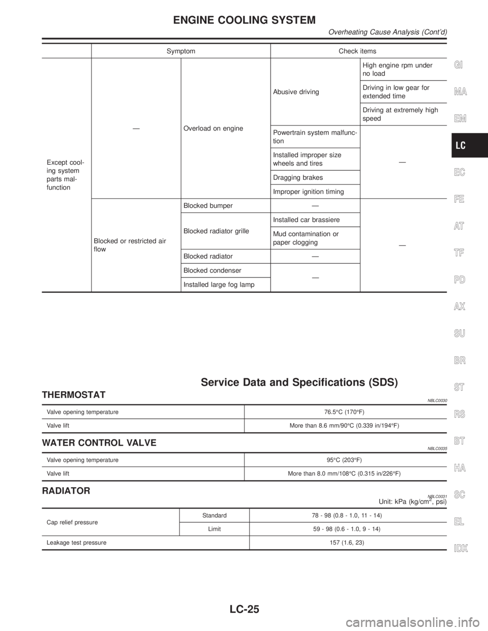
Symptom Check items
Except cool-
ing system
parts mal-
functionÐ Overload on engineAbusive drivingHigh engine rpm under
no load
Driving in low gear for
extended time
Driving at extremely high
speed
Powertrain system malfunc-
tion
Ð Installed improper size
wheels and tires
Dragging brakes
Improper ignition timing
Blocked or restricted air
flowBlocked bumper Ð
Ð Blocked radiator grilleInstalled car brassiere
Mud contamination or
paper clogging
Blocked radiator Ð
Blocked condenser
Ð
Installed large fog lamp
Service Data and Specifications (SDS)
THERMOSTATNBLC0030
Valve opening temperature76.5ÉC (170ÉF)
Valve liftMore than 8.6 mm/90ÉC (0.339 in/194ÉF)
WATER CONTROL VALVENBLC0035
Valve opening temperature95ÉC (203ÉF)
Valve liftMore than 8.0 mm/108ÉC (0.315 in/226ÉF)
RADIATORNBLC0031Unit: kPa (kg/cm2, psi)
Cap relief pressureStandard 78 - 98 (0.8 - 1.0, 11 - 14)
Limit 59 - 98 (0.6 - 1.0,9-14)
Leakage test pressure157 (1.6, 23)
GI
MA
EM
EC
FE
AT
TF
PD
AX
SU
BR
ST
RS
BT
HA
SC
EL
IDX
ENGINE COOLING SYSTEM
Overheating Cause Analysis (Cont'd)
LC-25
Page 2009 of 2395
SMA857C
SMA858C
Changing Engine CoolantNBMA0011WARNING:
To avoid the danger of being scalded, never change the cool-
ant when the engine is hot.
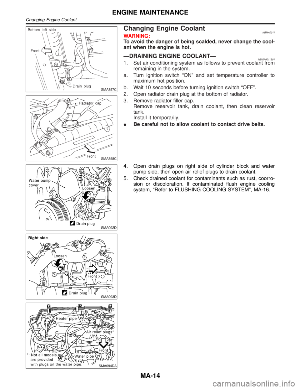
ÐDRAINING ENGINE COOLANTÐNBMA0011S011. Set air conditioning system as follows to prevent coolant from
remaining in the system.
a. Turn ignition switch ªONº and set temperature controller to
maximum hot position.
b. Wait 10 seconds before turning ignition switch ªOFFº.
2. Open radiator drain plug at the bottom of radiator.
3. Remove radiator filler cap.
Remove reservoir tank, drain coolant, then clean reservoir
tank.
Install it temporarily.
IBe careful not to allow coolant to contact drive belts.
SMA092D
SMA093D
SMA094DA
4. Open drain plugs on right side of cylinder block and water
pump side, then open air relief plugs to drain coolant.
5. Check drained coolant for contaminants such as rust, coorro-
sion or discoloration. If contaminated flush engine cooling
system, ªRefer to FLUSHING COOLING SYSTEMº, MA-16.
ENGINE MAINTENANCE
Changing Engine Coolant
MA-14
Page 2010 of 2395
SMA182B
ÐREFILLING ENGINE COOLANTÐNBMA0011S021. Install reservoir tank, radiator drain plug, and cylinder block
drain plugs.
IApply sealant to the thread of cylinder block drain plugs.
:8-11N´m(0.8 - 1.2 kg-m, 70 - 104 in-lb) Front side
: 18 - 21 N´m (1.8 - 2.2 kg-m, 13 - 15 ft-lb) Right side
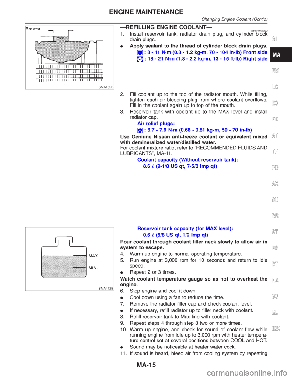
2. Fill coolant up to the top of the radiator mouth. While filling,
tighten each air bleeding plug from where coolant overflows.
Fill in the coolant again up to top of the mouth.
3. Reservoir tank with coolant up to the MAX level and install
radiator cap.
Air relief plugs:
: 6.7 - 7.9 N´m (0.68 - 0.81 kg-m, 59 - 70 in-lb)
Use Geniune Nissan anti-freeze coolant or equivalent mixed
with demineralized water/distilled water.
For coolant mixture ratio, refer to ªRECOMMENDED FLUIDS AND
LUBRICANTSº, MA-11.
Coolant capacity (Without reservoir tank):
8.6(9-1/8 US qt, 7-5/8 Imp qt)
SMA412B
Reservoir tank capacity (for MAX level):
0.6(5/8 US qt, 1/2 Imp qt)
Pour coolant through coolant filler neck slowly to allow air in
system to escape.
4. Warm up engine to normal operating temperature.
5. Run engine at 3,000 rpm for 10 seconds and return to idle
speed.
IRepeat 2 or 3 times.
Watch coolant temperature gauge so as not to overheat the
engine.
6. Stop engine and cool it down.
ICool down using a fan to reduce the time.
7. Remove the radiator filler cap and check coolant level.
IIf necessary, refill radiator up to filler neck with coolant.
8. Refill reservoir tank to Max line with coolant.
9. Repeat steps 4 through step 8 two or more times.
10. Warm up engine, and check for sound of coolant flow while
running engine from idle up to 3,000 rpm with heater tempera-
ture control set at several positions between COOL and HOT.
ISound may be noticeable at heater water cock.
11. If sound is heard, bleed air from cooling system by repeating
GI
EM
LC
EC
FE
AT
TF
PD
AX
SU
BR
ST
RS
BT
HA
SC
EL
IDX
ENGINE MAINTENANCE
Changing Engine Coolant (Cont'd)
MA-15
Page 2011 of 2395
steps 4 through 8 until coolant level no longer drops.
IClean excess coolant from engine.
ÐFLUSHING COOLING SYSTEMÐNBMA0011S031. Open air relief plug.
2. Fill radiator with water until water spills from the air relief holes,
then close air relief plugs. Fill radiator and reservoir tank with
water and reinstall radiator cap.
3. Run engine and warm it up to normal operating temperature.
4. Rev engine two or three times under no-load.
5. Stop engine and wait until it cools down.
6. Drain water.
7. Repeat steps 1 through 6 until clear water begins to drain from
radiator.
SMA803A
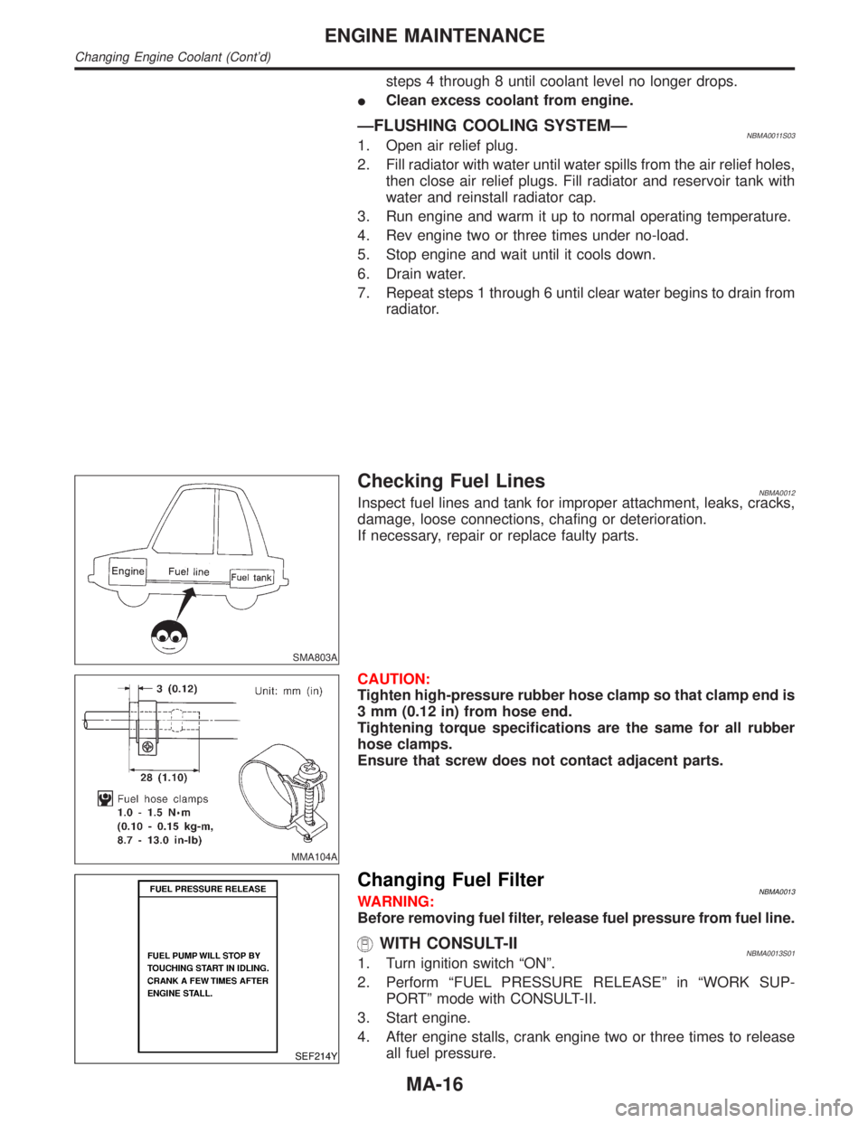
Checking Fuel LinesNBMA0012Inspect fuel lines and tank for improper attachment, leaks, cracks,
damage, loose connections, chafing or deterioration.
If necessary, repair or replace faulty parts.
MMA104A
CAUTION:
Tighten high-pressure rubber hose clamp so that clamp end is
3 mm (0.12 in) from hose end.
Tightening torque specifications are the same for all rubber
hose clamps.
Ensure that screw does not contact adjacent parts.
SEF214Y
Changing Fuel FilterNBMA0013WARNING:
Before removing fuel filter, release fuel pressure from fuel line.
WITH CONSULT-IINBMA0013S011. Turn ignition switch ªONº.
2. Perform ªFUEL PRESSURE RELEASEº in ªWORK SUP-
PORTº mode with CONSULT-II.
3. Start engine.
4. After engine stalls, crank engine two or three times to release
all fuel pressure.
ENGINE MAINTENANCE
Changing Engine Coolant (Cont'd)
MA-16