2001 INFINITI QX4 charging
[x] Cancel search: chargingPage 1810 of 2395
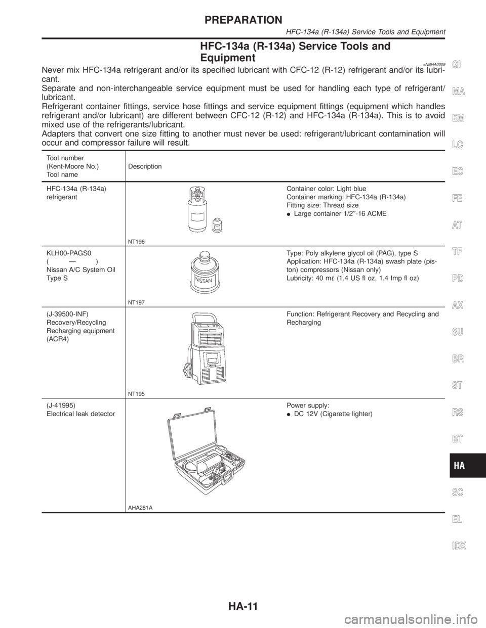
HFC-134a (R-134a) Service Tools and
Equipment
=NBHA0009Never mix HFC-134a refrigerant and/or its specified lubricant with CFC-12 (R-12) refrigerant and/or its lubri-
cant.
Separate and non-interchangeable service equipment must be used for handling each type of refrigerant/
lubricant.
Refrigerant container fittings, service hose fittings and service equipment fittings (equipment which handles
refrigerant and/or lubricant) are different between CFC-12 (R-12) and HFC-134a (R-134a). This is to avoid
mixed use of the refrigerants/lubricant.
Adapters that convert one size fitting to another must never be used: refrigerant/lubricant contamination will
occur and compressor failure will result.
Tool number
(Kent-Moore No.)
Tool nameDescription
HFC-134a (R-134a)
refrigerant
NT196
Container color: Light blue
Container marking: HFC-134a (R-134a)
Fitting size: Thread size
ILarge container 1/2²-16 ACME
KLH00-PAGS0
(Ð)
Nissan A/C System Oil
Type S
NT197
Type: Poly alkylene glycol oil (PAG), type S
Application: HFC-134a (R-134a) swash plate (pis-
ton) compressors (Nissan only)
Lubricity: 40 m(1.4 US fl oz, 1.4 Imp fl oz)
(J-39500-INF)
Recovery/Recycling
Recharging equipment
(ACR4)
NT195
Function: Refrigerant Recovery and Recycling and
Recharging
(J-41995)
Electrical leak detector
AHA281A
Power supply:
IDC 12V (Cigarette lighter)
GI
MA
EM
LC
EC
FE
AT
TF
PD
AX
SU
BR
ST
RS
BT
SC
EL
IDX
PREPARATION
HFC-134a (R-134a) Service Tools and Equipment
HA-11
Page 1811 of 2395
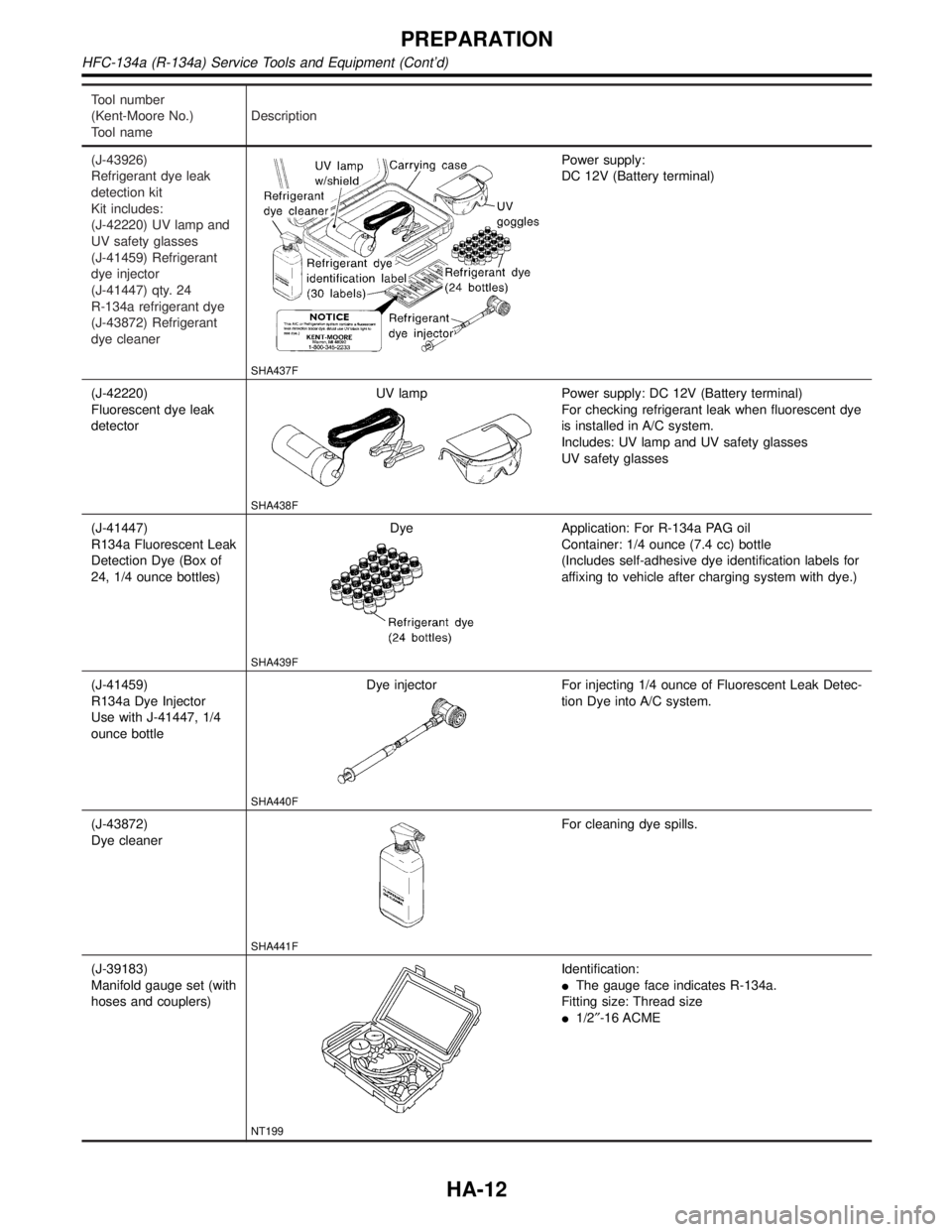
Tool number
(Kent-Moore No.)
Tool nameDescription
(J-43926)
Refrigerant dye leak
detection kit
Kit includes:
(J-42220) UV lamp and
UV safety glasses
(J-41459) Refrigerant
dye injector
(J-41447) qty. 24
R-134a refrigerant dye
(J-43872) Refrigerant
dye cleaner
SHA437F
Power supply:
DC 12V (Battery terminal)
(J-42220)
Fluorescent dye leak
detectorUV lamp
SHA438F
Power supply: DC 12V (Battery terminal)
For checking refrigerant leak when fluorescent dye
is installed in A/C system.
Includes: UV lamp and UV safety glasses
UV safety glasses
(J-41447)
R134a Fluorescent Leak
Detection Dye (Box of
24, 1/4 ounce bottles)Dye
SHA439F
Application: For R-134a PAG oil
Container: 1/4 ounce (7.4 cc) bottle
(Includes self-adhesive dye identification labels for
affixing to vehicle after charging system with dye.)
(J-41459)
R134a Dye Injector
Use with J-41447, 1/4
ounce bottleDye injector
SHA440F
For injecting 1/4 ounce of Fluorescent Leak Detec-
tion Dye into A/C system.
(J-43872)
Dye cleaner
SHA441F
For cleaning dye spills.
(J-39183)
Manifold gauge set (with
hoses and couplers)
NT199
Identification:
IThe gauge face indicates R-134a.
Fitting size: Thread size
I1/2²-16 ACME
PREPARATION
HFC-134a (R-134a) Service Tools and Equipment (Cont'd)
HA-12
Page 1943 of 2395
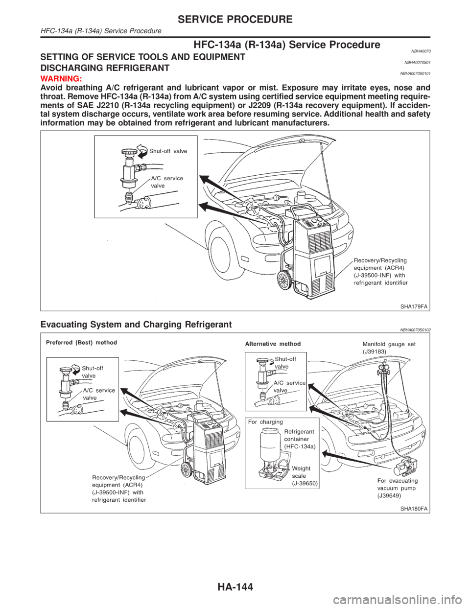
HFC-134a (R-134a) Service ProcedureNBHA0070SETTING OF SERVICE TOOLS AND EQUIPMENTNBHA0070S01DISCHARGING REFRIGERANTNBHA0070S0101WARNING:
Avoid breathing A/C refrigerant and lubricant vapor or mist. Exposure may irritate eyes, nose and
throat. Remove HFC-134a (R-134a) from A/C system using certified service equipment meeting require-
ments of SAE J2210 (R-134a recycling equipment) or J2209 (R-134a recovery equipment). If acciden-
tal system discharge occurs, ventilate work area before resuming service. Additional health and safety
information may be obtained from refrigerant and lubricant manufacturers.
SHA179FA
Evacuating System and Charging RefrigerantNBHA0070S0102
SHA180FA
SERVICE PROCEDURE
HFC-134a (R-134a) Service Procedure
HA-144
Page 1947 of 2395
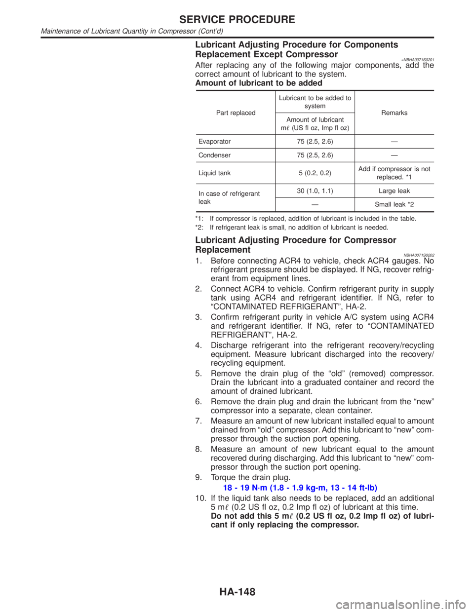
Lubricant Adjusting Procedure for Components
Replacement Except Compressor
=NBHA0071S0201After replacing any of the following major components, add the
correct amount of lubricant to the system.
Amount of lubricant to be added
Part replacedLubricant to be added to
system
Remarks
Amount of lubricant
m(US fl oz, Imp fl oz)
Evaporator 75 (2.5, 2.6) Ð
Condenser 75 (2.5, 2.6) Ð
Liquid tank 5 (0.2, 0.2)Add if compressor is not
replaced. *1
In case of refrigerant
leak30 (1.0, 1.1) Large leak
Ð Small leak *2
*1: If compressor is replaced, addition of lubricant is included in the table.
*2: If refrigerant leak is small, no addition of lubricant is needed.
Lubricant Adjusting Procedure for Compressor
Replacement
NBHA0071S02021. Before connecting ACR4 to vehicle, check ACR4 gauges. No
refrigerant pressure should be displayed. If NG, recover refrig-
erant from equipment lines.
2. Connect ACR4 to vehicle. Confirm refrigerant purity in supply
tank using ACR4 and refrigerant identifier. If NG, refer to
ªCONTAMINATED REFRIGERANTº, HA-2.
3. Confirm refrigerant purity in vehicle A/C system using ACR4
and refrigerant identifier. If NG, refer to ªCONTAMINATED
REFRIGERANTº, HA-2.
4. Discharge refrigerant into the refrigerant recovery/recycling
equipment. Measure lubricant discharged into the recovery/
recycling equipment.
5. Remove the drain plug of the ªoldº (removed) compressor.
Drain the lubricant into a graduated container and record the
amount of drained lubricant.
6. Remove the drain plug and drain the lubricant from the ªnewº
compressor into a separate, clean container.
7. Measure an amount of new lubricant installed equal to amount
drained from ªoldº compressor. Add this lubricant to ªnewº com-
pressor through the suction port opening.
8. Measure an amount of new lubricant equal to the amount
recovered during discharging. Add this lubricant to ªnewº com-
pressor through the suction port opening.
9. Torque the drain plug.
18 - 19 N´m (1.8 - 1.9 kg-m, 13 - 14 ft-lb)
10. If the liquid tank also needs to be replaced, add an additional
5m(0.2 US fl oz, 0.2 Imp fl oz) of lubricant at this time.
Do not add this 5 m(0.2 US fl oz, 0.2 Imp fl oz) of lubri-
cant if only replacing the compressor.
SERVICE PROCEDURE
Maintenance of Lubricant Quantity in Compressor (Cont'd)
HA-148
Page 1954 of 2395
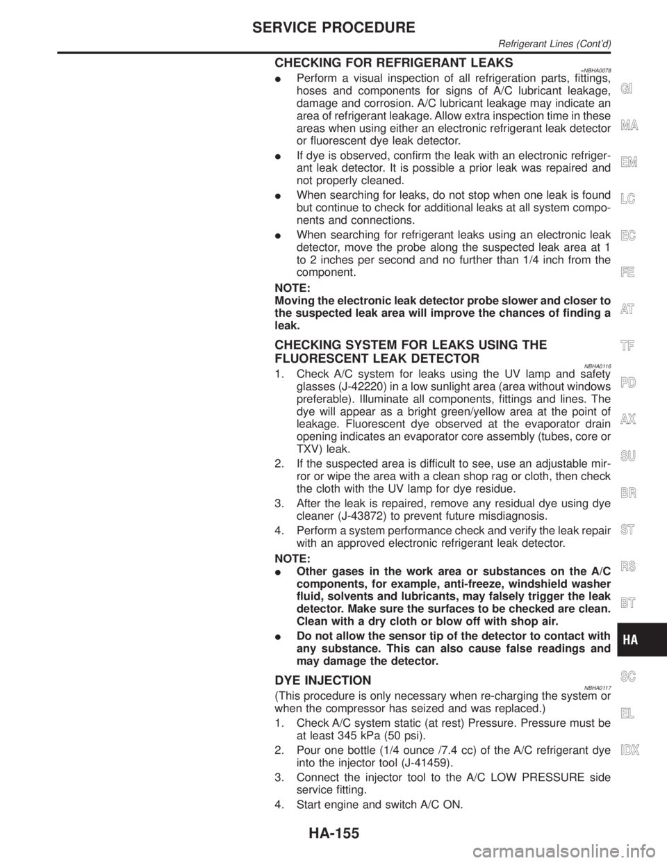
CHECKING FOR REFRIGERANT LEAKS=NBHA0078IPerform a visual inspection of all refrigeration parts, fittings,
hoses and components for signs of A/C lubricant leakage,
damage and corrosion. A/C lubricant leakage may indicate an
area of refrigerant leakage. Allow extra inspection time in these
areas when using either an electronic refrigerant leak detector
or fluorescent dye leak detector.
IIf dye is observed, confirm the leak with an electronic refriger-
ant leak detector. It is possible a prior leak was repaired and
not properly cleaned.
IWhen searching for leaks, do not stop when one leak is found
but continue to check for additional leaks at all system compo-
nents and connections.
IWhen searching for refrigerant leaks using an electronic leak
detector, move the probe along the suspected leak area at 1
to 2 inches per second and no further than 1/4 inch from the
component.
NOTE:
Moving the electronic leak detector probe slower and closer to
the suspected leak area will improve the chances of finding a
leak.
CHECKING SYSTEM FOR LEAKS USING THE
FLUORESCENT LEAK DETECTOR
NBHA01161. Check A/C system for leaks using the UV lamp and safety
glasses (J-42220) in a low sunlight area (area without windows
preferable). Illuminate all components, fittings and lines. The
dye will appear as a bright green/yellow area at the point of
leakage. Fluorescent dye observed at the evaporator drain
opening indicates an evaporator core assembly (tubes, core or
TXV) leak.
2. If the suspected area is difficult to see, use an adjustable mir-
ror or wipe the area with a clean shop rag or cloth, then check
the cloth with the UV lamp for dye residue.
3. After the leak is repaired, remove any residual dye using dye
cleaner (J-43872) to prevent future misdiagnosis.
4. Perform a system performance check and verify the leak repair
with an approved electronic refrigerant leak detector.
NOTE:
IOther gases in the work area or substances on the A/C
components, for example, anti-freeze, windshield washer
fluid, solvents and lubricants, may falsely trigger the leak
detector. Make sure the surfaces to be checked are clean.
Clean with a dry cloth or blow off with shop air.
IDo not allow the sensor tip of the detector to contact with
any substance. This can also cause false readings and
may damage the detector.
DYE INJECTIONNBHA0117(This procedure is only necessary when re-charging the system or
when the compressor has seized and was replaced.)
1. Check A/C system static (at rest) Pressure. Pressure must be
at least 345 kPa (50 psi).
2. Pour one bottle (1/4 ounce /7.4 cc) of the A/C refrigerant dye
into the injector tool (J-41459).
3. Connect the injector tool to the A/C LOW PRESSURE side
service fitting.
4. Start engine and switch A/C ON.
GI
MA
EM
LC
EC
FE
AT
TF
PD
AX
SU
BR
ST
RS
BT
SC
EL
IDX
SERVICE PROCEDURE
Refrigerant Lines (Cont'd)
HA-155
Page 1959 of 2395
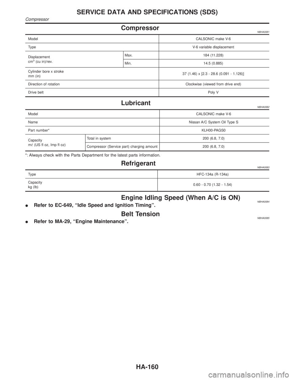
CompressorNBHA0081
ModelCALSONIC make V-6
TypeV-6 variable displacement
Displacement
cm
3(cu in)/rev.Max. 184 (11.228)
Min. 14.5 (0.885)
Cylinder bore x stroke
mm (in)37 (1.46) x [2.3 - 28.6 (0.091 - 1.126)]
Direction of rotationClockwise (viewed from drive end)
Drive beltPoly V
LubricantNBHA0082
ModelCALSONIC make V-6
NameNissan A/C System Oil Type S
Part number*KLH00-PAGS0
Capacity
m(US fl oz, Imp fl oz)Total in system 200 (6.8, 7.0)
Compressor (Service part) charging amount 200 (6.8, 7.0)
*: Always check with the Parts Department for the latest parts information.
RefrigerantNBHA0083
TypeHFC-134a (R-134a)
Capacity
kg (lb)0.60 - 0.70 (1.32 - 1.54)
Engine Idling Speed (When A/C is ON)NBHA0084IRefer to EC-649, ªIdle Speed and Ignition Timingº.
Belt TensionNBHA0085IRefer to MA-29, ªEngine Maintenanceº.
SERVICE DATA AND SPECIFICATIONS (SDS)
Compressor
HA-160
Page 1961 of 2395
A
AAC/V - Wiring diagram ...............................EC-425
ABS - Wiring diagram ....................................BR-37
ABS sensor rotor ........................................AX-6, 19
Absolute pressure sensor ............................EC-158
A/C air flow .....................................................HA-25
A/C component layout ....................................HA-19
A/C compressor clutch removal and
installation .................................................HA-150
A/C compressor precaution..............................HA-6
A/C compressor special service tool..............HA-10
A/C control operation (auto A/C) ....................HA-23
A/C diagnostic work flow (auto A/C) ..............HA-65
A/C HFC134a (R134a) system
precaution .....................................................HA-2
A/C HFC134a (R134a) system service
procedure ..................................................HA-144
A/C HFC134a (R134a) system service
tools.............................................................HA-11
A/C HFC134a system service equip-
ment precaution ............................................HA-7
A/C lubricant (R134a)...................................HA-146
A/C operational check ....................................HA-66
A/C performance chart .................................HA-116
A/C performance test diagnoses ..................HA-114
A/C relay .......................................................HA-110
A/C self-diagnoses (auto A/C)........................HA-44
A/C service data specification ......................HA-160
A/C system description (auto A/C) .................HA-23
A/C trouble diagnoses (auto A/C) ..................HA-27
A/C, A - Wiring diagram ...........................HA-31, 36
Accelerator control system ...............................FE-3
Accelerator wire adjustment .............................FE-3
Actuator lever (Transfer) ...............................TF-120
Air bag ............................................................RS-10
Air bag disposal..............................................RS-22
Air bag precautions ...........................................GI-3
Air bleeding for brake system ..........................BR-8
Air cleaner filter replacement .........................MA-17
Air conditioner cut control ..............................EC-31
Air flow meter - See Mass air flow
sensor .......................................................EC-150
Air mix door control linkage adjustment.........HA-85
Air mix. door motor ................................HA-82, 141
Air spoiler, rear................................................BT-35
All - mode 4WD system ..................................TF-10
Alternator ........................................................SC-28
Ambient sensor ............................................HA-129
Angular tightening application..........................EM-3
Antenna - See Power antenna .....................EL-169
Anti-lock brake system - Wiring
diagram .......................................................BR-37
AP/SEN - Wiring diagram ............................EC-160
ASCD (automatic speed control device) ......EL-221
ASCD - Wiring diagram ................................EL-225
A/T - Wiring diagram - AT - FTS ...................AT-107
A/T - Wiring diagram - AT - MAIN ...................AT-96
A/T - Wiring diagram - AT - PNP/SW............AT-101A/T - Wiring diagram - AT - VSS A/T ............AT-113
A/T control ....................................................EC-440
A/T diagnosis communication line................EC-603
A/T fluid temperature sensor .........................AT-110
A/T self-diagnoses...........................................AT-46
A/T shift lock system .....................................AT-265
A/T shift lock system - Wiring diagram .........AT-266
A/T trouble diagnoses .....................................AT-53
A/T Wiring diagram - AT - ENG SS...............AT-117
A/T Wiring diagram AT - 1ST ........................AT-123
A/T Wiring diagram AT - 2ND .......................AT-129
A/T Wiring diagram AT - 3RD .......................AT-135
A/T Wiring diagram AT - 4TH ........................AT-142
A/T Wiring diagram AT - BA/FTS ..................AT-192
A/T Wiring diagram AT - LPSV .....................AT-164
A/T Wiring diagram AT - NONDTC ...............AT-215
A/T Wiring diagram AT - OVRCSV ...............AT-187
A/T Wiring diagram AT - SSV/A ....................AT-169
A/T Wiring diagram AT - SSV/B ....................AT-173
A/T Wiring diagram AT - TCCSIG .................AT-156
A/T Wiring diagram AT - TCV .......................AT-150
A/T Wiring diagram AT - TPS........................AT-179
A/T Wiring diagram AT - VSSMTR................AT-199
AT/C - Wiring diagram ..................................EC-442
ATP switch.....................................................TF-112
ATP warning lamp .........................................TF-102
Audio .............................................................EL-160
AUDIO - Wiring diagram ...............................EL-162
Audio and A/C control removal and
installation - See Instrument panel .............BT-21
AUT/DP - Wiring diagram .............................EL-191
Auto air conditioner - Wiring diagram ......HA-31, 36
Automatic amplifier...................................HA-40, 72
Automatic drive positioner ............................EL-186
Automatic speed control system - See
ASCD ........................................................EL-221
Automatic transmission fluid
replacement ................................................MA-21
Automatic transmission number ......................GI-43
Auxiliary air control (AAC) valve ..................EC-422
Axle housing (rear) .........................................AX-19
B
Back door ........................................................BT-15
Back door opener - See Back door ................BT-15
Back door trim.................................................BT-34
Back-up lamp ..................................................EL-69
BACK/L - Wiring diagram................................EL-69
Ball joint (front) ...............................................SU-12
Base idle air volume initialiging......................EC-57
Basic inspection ...........................................EC-101
Battery ..............................................................SC-4
Battery/Starting/Charging System
Tester ................................................SC-7, 12, 21
Blower motor ..................................................HA-95
Body alignment ...............................................BT-57
Brake booster .................................................BR-19
Brake control valve (Proportioning
valve)...........................................................BR-11
ALPHABETICAL INDEX
IDX-2
Page 1962 of 2395
Brake fluid change ...........................................BR-7
Brake fluid level .............................................MA-25
Brake fluid level and line check .......................BR-7
Brake hydraulic line ..........................................BR-9
Brake inspection ............................................MA-25
Brake lines and cables inspection .................MA-25
Brake lining wear temporary checking ..........MA-26
Brake master cylinder ....................................BR-16
Brake pedal ....................................................BR-14
Bulb specifications ........................................EL-456
Bumper, front ..................................................BT-12
Bumper, rear ...................................................BT-15
BYPS/V - Wiring diagram ....................EC-587, 594
C
Camshaft inspection ......................................EM-42
Camshaft position sensor (PHASE) .............EC-342
Canister-See EVAP canister ..........................EC-32
Center bearing assembly (propeller
shaft) .............................................................PD-9
Center bearing disassembly (propeller
shaft) .............................................................PD-7
Center case (Transfer) ..................................TF-123
CHARGE - Wiring diagram ............................SC-20
Charging system ............................................SC-19
Chassis and body maintenance ....................MA-21
CHIME - Wiring diagram...............................EL-127
CIGAR - Wiring diagram ...............................EL-148
Cigarette lighter.............................................EL-148
Circuit breaker.................................................EL-16
CKPS - Wiring diagram ................................EC-334
Closed loop control (Left bank) ....................EC-491
Closed loop control (Right bank) .................EC-491
Closed throttle position switch .....................EC-431
Clutch drum (Transfer) ..................................TF-125
Clutch force release limit adjustment .............TF-39
Clutch pressure switch (Transfer) .................TF-111
Coil spring (front)..............................................SU-8
Coil spring (rear) ............................................SU-18
Collision diagnosis..........................................RS-59
Combination lamp, front, removal and
installation ...................................................BT-12
Combination lamp, rear, removal and
installation ...................................................BT-35
Combination meter..........................................EL-94
Combination meter removal and instal-
lation - See Instrument panel ......................BT-21
Combination switch .........................................EL-28
COMPAS - Wiring diagram ...........................EL-111
Compass .......................................................EL-110
Component Location (auto A/C).....................HA-27
Compression pressure ...................................EM-14
Compressor clutch removal and
installation .................................................HA-150
Compressor precaution ....................................HA-6
Compressor special service tool ....................HA-10
Connecting rod...............................................EM-65
Connecting rod bearing clearance.................EM-69
Connecting rod bushing clearance ................EM-70Connector inspection .......................................GI-21
Console box - See Instrument panel ..............BT-21
CONSULT for ABS .........................................BR-43
CONSULT for all-mode 4WD ..........................TF-30
CONSULT for engine .....................................EC-81
CONSULT-II general information .....................GI-38
Control valve (A/T) ........................................AT-301
Control valve (Transfer) ................................TF-128
Converter housing installation .......................AT-278
Coolant mixture ratio......................................MA-12
Coolant replacement ......................................MA-14
Cooling circuit (engine) ...................................LC-10
``Crankcase emission control system -
See positive crankcase ventilation''............EC-38
Crankshaft ......................................................EM-67
Crankshaft position sensor (POS) ...............EC-334
Crankshaft position sensor (POS)
chipping ....................................................EC-517
Crankshaft position sensor (REF) ................EC-510
Cruise control - See ASCD ...........................EL-221
Cylinder block ................................................EM-61
Cylinder head .................................................EM-38
Cylinder head bolt tightening .........................EM-49
D
Data link connector for Consult......................EC-81
Daytime light system.......................................EL-46
Daytime running light - See Daytime
light system .................................................EL-46
DEF - Wiring diagram ...................................EL-153
Detonation sensor - See Knock sensor .......EC-328
Diagnostic trouble code (DTC) for OBD
system ....................................................EC-8, 60
Diagnostic trouble code (DTC) inspec-
tion priority chart .......................................EC-116
Differential carrier assembly.....................PD-30, 57
Differential carrier disassembly ......................PD-44
Differential gear oil replacement ....................MA-24
Dimensions ......................................................GI-43
D/LOCK - Wiring diagram .............................EL-256
Dome light - See Interior lamp .......................EL-88
Door glass .......................................................BT-18
Door lock .........................................................BT-18
Door mirror ......................................................BT-56
Door trim .........................................................BT-30
Door, front .......................................................BT-18
Door, rear ........................................................BT-20
Drive belt inspection ......................................MA-13
Drive chain (Transfer) ...................................TF-125
Drive pinion diff. inspection ......................PD-23, 47
Drive pinion height ...................................PD-25, 53
Drive plate runout ..........................................EM-70
Drive shaft (front)............................................AX-10
Dropping resistor (A/T) ..................................AT-167
DTC work support ..........................................EC-93
DTRL - Wiring diagram ...................................EL-51
GI
MA
EM
LC
EC
FE
AT
TF
PD
AX
SU
BR
ST
RS
BT
HA
SC
EL
ALPHABETICAL INDEX
IDX-3