2001 INFINITI QX4 Idle air
[x] Cancel search: Idle airPage 563 of 2395

Multiport Fuel Injection (MFI) System
DESCRIPTIONNBEC0014Input/Output Signal ChartNBEC0014S01
Sensor Input Signal to ECMECM func-
tionActuator
Crankshaft position sensor (POS) Engine speed (POS signal)
Fuel injec-
tion & mix-
ture ratio
controlInjectors Crankshaft position sensor (REF) Engine speed (REF signal)
Camshaft position sensor (PHASE) Piston position
Mass air flow sensor Amount of intake air
Engine coolant temperature sensor Engine coolant temperature
Heated oxygen sensor 1 (front) Density of oxygen in exhaust gas
Throttle position sensorThrottle position
Throttle valve idle position
Park/neutral position (PNP) switch Gear position
Vehicle speed sensor Vehicle speed
Ignition switch Start signal
Air conditioner switch Air conditioner operation
Knock sensor Engine knocking condition
Battery Battery voltage
Absolute pressure sensor Ambient air barometric pressure
Power steering oil pressure switch Power steering operation
Heated oxygen sensor 2 (rear)* Density of oxygen in exhaust gas
*: Under normal conditions, this sensor is not for engine control operation.
Basic Multiport Fuel Injection SystemNBEC0014S02The amount of fuel injected from the fuel injector is determined by the ECM. The ECM controls the length of
time the valve remains open (injection pulse duration). The amount of fuel injected is a program value in the
ECM memory. The program value is preset by engine operating conditions. These conditions are determined
by input signals (for engine speed and intake air) from both the crankshaft position sensor and the mass air
flow sensor.
Various Fuel Injection Increase/Decrease CompensationNBEC0014S03In addition, the amount of fuel injected is compensated to improve engine performance under various oper-
ating conditions as listed below.
IDuring warm-up
IWhen starting the engine
IDuring acceleration
IHot-engine operation
IWhen selector lever is changed from ªNº to ªDº
IHigh-load, high-speed operation
IDuring deceleration
IDuring high engine speed operation
ENGINE AND EMISSION BASIC CONTROL SYSTEM DESCRIPTION
Multiport Fuel Injection (MFI) System
EC-28
Page 565 of 2395

Fuel Injection TimingNBEC0014S07
SEF179U
Two types of systems are used.
Sequential Multiport Fuel Injection System
NBEC0014S0701Fuel is injected into each cylinder during each engine cycle according to the firing order. This system is used
when the engine is running.
Simultaneous Multiport Fuel Injection System
NBEC0014S0702Fuel is injected simultaneously into all six cylinders twice each engine cycle. In other words, pulse signals of
the same width are simultaneously transmitted from the ECM.
The six injectors will then receive the signals two times for each engine cycle.
This system is used when the engine is being started and/or if the fail-safe system (CPU) is operating.
Fuel Shut-offNBEC0014S08Fuel to each cylinder is cut off during deceleration or operation of the engine at excessively high speeds.
Electronic Ignition (EI) System
DESCRIPTIONNBEC0015Input/Output Signal ChartNBEC0015S01
Sensor Input Signal to ECMECM func-
tionActuator
Crankshaft position sensor (POS) Engine speed (POS signal)
Ignition
timing con-
trolPower transistor Crankshaft position sensor (REF) Engine speed (REF signal)
Camshaft position sensor (PHASE) Piston position
Mass air flow sensor Amount of intake air
Engine coolant temperature sensor Engine coolant temperature
Throttle position sensorThrottle position
Throttle valve idle position
Vehicle speed sensor Vehicle speed
Ignition switch Start signal
Knock sensor Engine knocking
Park/neutral position (PNP) switch Gear position
Battery Battery voltage
ENGINE AND EMISSION BASIC CONTROL SYSTEM DESCRIPTION
Multiport Fuel Injection (MFI) System (Cont'd)
EC-30
Page 566 of 2395

System DescriptionNBEC0015S02
SEF742M
The ignition timing is controlled by the ECM to maintain the best air-fuel ratio for every running condition of
the engine. The ignition timing data is stored in the ECM. This data forms the map shown.
The ECM receives information such as the injection pulse width and camshaft position sensor signal. Com-
puting this information, ignition signals are transmitted to the power transistor.
e.g., N: 1,800 rpm, Tp: 1.50 msec
A ÉBTDC
During the following conditions, the ignition timing is revised by the ECM according to the other data stored
in the ECM.
IAt starting
IDuring warm-up
IAt idle
IAt low battery voltage
IDuring acceleration
The knock sensor retard system is designed only for emergencies. The basic ignition timing is programmed
within the anti-knocking zone, if recommended fuel is used under dry conditions. The retard system does not
operate under normal driving conditions. If engine knocking occurs, the knock sensor monitors the condition.
The signal is transmitted to the ECM. The ECM retards the ignition timing to eliminate the knocking condition.
Air Conditioning Cut Control
DESCRIPTIONNBEC0016Input/Output Signal ChartNBEC0016S01
Sensor Input Signal to ECM ECM function Actuator
Air conditioner switch Air conditioner ªONº signal
Air conditioner
cut controlAir conditioner relay Throttle position sensor Throttle valve opening angle
Crankshaft position sensor (POS) Engine speed (POS signal)
Crankshaft position sensor (REF) Engine speed (REF signal)
Engine coolant temperature sensor Engine coolant temperature
Ignition switch Start signal
Vehicle speed sensor Vehicle speed
Refrigerant pressure sensor Refrigerant pressure
Power steering oil pressure switch Power steering operation
System DescriptionNBEC0016S02This system improves engine operation when the air conditioner is used.
Under the following conditions, the air conditioner is turned off.
IWhen the accelerator pedal is fully depressed.
IWhen cranking the engine.
IAt high engine speeds.
GI
MA
EM
LC
FE
AT
TF
PD
AX
SU
BR
ST
RS
BT
HA
SC
EL
IDX
ENGINE AND EMISSION BASIC CONTROL SYSTEM DESCRIPTION
Electronic Ignition (EI) System (Cont'd)
EC-31
Page 573 of 2395

SEF372Q
SEF559A
Positive Crankcase Ventilation
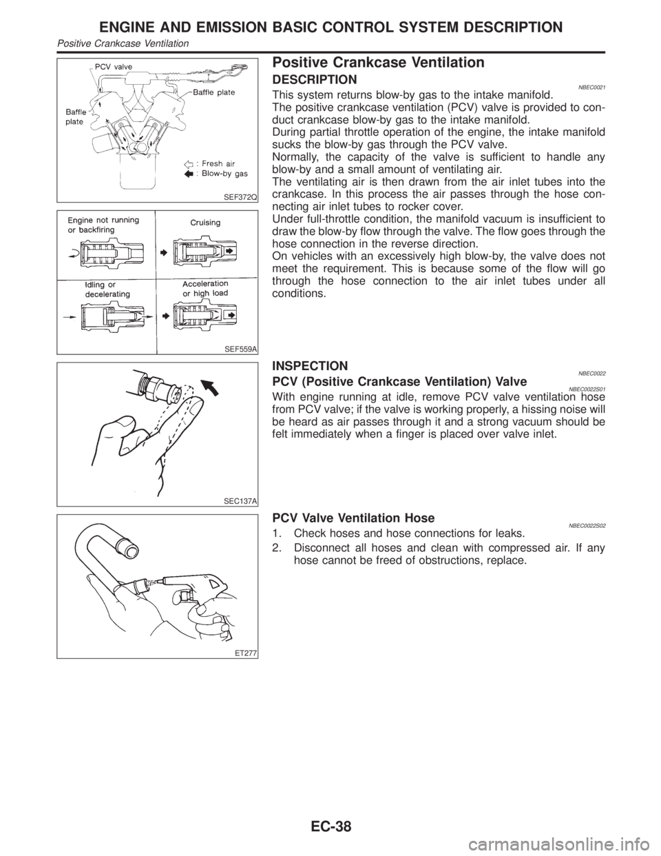
DESCRIPTIONNBEC0021This system returns blow-by gas to the intake manifold.
The positive crankcase ventilation (PCV) valve is provided to con-
duct crankcase blow-by gas to the intake manifold.
During partial throttle operation of the engine, the intake manifold
sucks the blow-by gas through the PCV valve.
Normally, the capacity of the valve is sufficient to handle any
blow-by and a small amount of ventilating air.
The ventilating air is then drawn from the air inlet tubes into the
crankcase. In this process the air passes through the hose con-
necting air inlet tubes to rocker cover.
Under full-throttle condition, the manifold vacuum is insufficient to
draw the blow-by flow through the valve. The flow goes through the
hose connection in the reverse direction.
On vehicles with an excessively high blow-by, the valve does not
meet the requirement. This is because some of the flow will go
through the hose connection to the air inlet tubes under all
conditions.
SEC137A
INSPECTIONNBEC0022PCV (Positive Crankcase Ventilation) ValveNBEC0022S01With engine running at idle, remove PCV valve ventilation hose
from PCV valve; if the valve is working properly, a hissing noise will
be heard as air passes through it and a strong vacuum should be
felt immediately when a finger is placed over valve inlet.
ET277
PCV Valve Ventilation HoseNBEC0022S021. Check hoses and hose connections for leaks.
2. Disconnect all hoses and clean with compressed air. If any
hose cannot be freed of obstructions, replace.
ENGINE AND EMISSION BASIC CONTROL SYSTEM DESCRIPTION
Positive Crankcase Ventilation
EC-38
Page 579 of 2395

IAir intake system
(Oil filler cap, oil level gauge, etc.)
IFuel pressure
IEngine compression
IThrottle valve
IEvaporative emission system
2) On air conditioner equipped models, checks should be carried out while the air conditioner is ªOFFº.
3) On automatic transmission equipped models, when checking idle rpm, ignition timing and mixture ratio,
checks should be carried out while shift lever is in ªNº position.
4) When measuring ªCOº percentage, insert probe more than 40 cm (15.7 in) into tail pipe.
5) Turn off headlamps, heater blower, rear defogger.
6) Keep front wheels pointed straight ahead.
7) Make the check after the cooling fan has stopped.
BASIC SERVICE PROCEDURE
Idle Speed/Ignition Timing/Idle Mixture Ratio Adjustment (Cont'd)
EC-44
Page 581 of 2395

INSPECTION PROCEDURE=NBEC0028S02
1 INSPECTION START
1. Visually check the following:
IAir cleaner clogging
IHoses and ducts for leaks
IElectrical connectors
IGasket
IThrottle valve and throttle position sensor operation
2. Start engine and warm it up until engine coolant temperature indicator points to the middle of gauge.
Ensure engine stays below 1,000 rpm.
SEF976U
3. Open engine hood and run engine at about 2,000 rpm for about 2 minutes under no-load.
SEF977U
4. Make sure that no DTC is displayed with CONSULT-II or GST.
OK or NG
OK©GO TO 3.
NG©GO TO 2.
2 REPAIR OR REPLACE
Repair or replace components as necessary according to corresponding ªDiagnostic Procedureº.
©GO TO 3.
3 CHECK TARGET IDLE SPEED
With CONSULT-II
1. Start engine and warm it up to normal operating temperature.
2. Select ªENG SPEEDº in ªDATA MONITORº mode with CONSULT-II.
3. Check idle speed.
750±50 rpm (in ªPº or ªNº position)
Without CONSULT-II
1. Start engine and warm it up to normal operating temperature.
2. Check idle speed.
750±50 rpm (in ªPº or ªNº position)
OK or NG
OK©GO TO 12.
NG©GO TO 4.
BASIC SERVICE PROCEDURE
Idle Speed/Ignition Timing/Idle Mixture Ratio Adjustment (Cont'd)
EC-46
Page 582 of 2395

4 PERFORM IDLE AIR VOLUME LEARNING
Refer to ªIdle Air Volume Learningº, EC-57.
Which is the result CMPLT or INCMP?
CMPLT or INCMP
CMPLT©GO TO 5.
INCMP©1. Follow the construction of ªIdle Air Volume Leaningº.
2. GO TO 4.
5 CHECK TARGET IDLE SPEED AGAIN
With CONSULT-II
1. Start engine and warm it up to normal operating temperature.
2. Select ªENG SPEEDº in ªDATA MONITORº mode with CONSULT-II.
3. Check idle speed.
750±50 rpm (in ªPº or ªNº position)
Without CONSULT-II
1. Start engine and warm it up to normal operating temperature.
2. Check idle speed.
750±50 rpm (in ªPº or ªNº position)
OK or NG
OK©GO TO 10.
NG©GO TO 6.
6 REPLACE IACV-AAC VALVE
Replace IACV-AAC valve.
©GO TO 7.
7 PERFORM IDLE AIR VOLUME LEARNING
Refer to ªIdle Air Volume Learningº, EC-57.
Which is the result CMPLT or INCMP?
CMPLT or INCMP
CMPLT©GO TO 8.
INCMP©1. Follow the construction of ªIdle Air Volume Learningº.
2. GO TO 4.
8 CHECK TARGET IDLE SPEED AGAIN
With CONSULT-II
1. Start engine and warm it up to normal operating temperature.
2. Select ªENG SPEEDº in ªDATA MONITORº mode with CONSULT-II.
3. Check idle speed.
750±50 rpm (in ªPº or ªNº position)
Without CONSULT-II
1. Start engine and warm it up to normal operating temperature.
2. Check idle speed.
750±50 rpm (in ªPº or ªNº position)
OK or NG
OK©GO TO 10.
NG©GO TO 9.
GI
MA
EM
LC
FE
AT
TF
PD
AX
SU
BR
ST
RS
BT
HA
SC
EL
IDX
BASIC SERVICE PROCEDURE
Idle Speed/Ignition Timing/Idle Mixture Ratio Adjustment (Cont'd)
EC-47
Page 583 of 2395

9 CHECK ECM FUNCTION
1. Substitute another known-good ECM to check ECM function. (ECM may be the cause of a problem, but this is rarely
the case.)
2. Perform initialization of IVIS (NATS) system and registration of IVIS (NATS) ignition key IDs. Refer to ªIVIS (INFINITI
VEHICLE IMMOBILIZER SYSTEM Ð NATS)º, EC-74.
©GO TO 4.
10 CHECK IGNITION TIMING
1. Start engine and warm it up to normal operating temperature.
2. Check ignition timing at idle using a timing light.
SEF572X
15ɱ5É BTDC (in ªPº or ªNº position)
OK or NG
OK©GO TO 18.
NG©GO TO 11.
11 CHECK TIMING CHAIN INSTALLATION
Check timing chain installation. Refer to EM-29, ªInstallationº.
OK or NG
OK©GO TO 9.
NG©1. Repair the timing chain installation.
2. GO TO 4.
12 CHECK IGNITION TIMING
1. Start engine and let it idle.
2. Check ignition timing at idle using a timing light.
SEF572X
15ɱ5É BTDC (in ªPº or ªNº position)
OK or NG
OK©GO TO 18.
NG©GO TO 13.
BASIC SERVICE PROCEDURE
Idle Speed/Ignition Timing/Idle Mixture Ratio Adjustment (Cont'd)
EC-48